1
Abstract—Pneumatic nebulizers (as variations based on the Collison nebulizer) have been widely used for producing fine aerosol droplets from a liquid material. The basic working principle of those nebulizers has been qualitatively described as utilization of the negative pressure associated with an expanding gas jet to syphon liquid into the jet stream, then to blow and shear into liquid sheets, filaments, and eventually droplets. Detailed quantitative analysis based on fluid mechanics theory is desirable, to gain in-depth understanding of the liquid aspiration mechanism among other aspects of the Collison nebulizer behavior. The purpose of present work is to investigate the nature of negative pressure distribution associated with compressible gas jet flow in the Collison nebulizer by a computational fluid dynamics (CFD) analysis, using an OpenFOAM® compressible flow solver. The value of the negative pressure associated with a gas jet flow is examined by varying geometric parameters of the jet expansion channel adjacent to the outlet of jet orifice. Such an analysis can provide valuable insights into fundamental mechanisms in liquid aspiration process, helpful for effective design of improved pneumatic atomizer in the Aerosol Jet® direct-write system for micro-feature, high-aspect-ratio material deposition in additive manufacturing.
Keywords—Collison nebulizer, compressible gas jet flow, liquid aspiration, pneumatic atomization.
I. INTRODUCTION
HE original motivation to develop pneumatic nebulizers was for producing medical aerosols in the inhalation therapy [1]. Among many variations, the Collison nebulizer (introduced by W. E. Collison) has been the most representative one, widely used in applications extended even beyond therapeutic inhalers. For example, the Aerosol Jet® direct-write systems typically include a pneumatic atomizer with similar configuration as the Collison nebulizer, for producing aerosol droplets of functional ink material in the size range of 1--5 m [2, 3]. This type of pneumatic nebulizer has shown capabilities of effectively atomizing liquid materials much more viscous than the usual therapeutic liquids, enabling Aerosol Jet® to print inks with high concentrations of functional materials. To further improve the pneumatic atomizer performance in Aerosol Jet® systems, it is important to understand detailed fluid dynamics and the effects of various parameters involved in the atomizer design.
Despite its wide usage in a variety of applications, the technical details about fluid dynamic behavior of the Collison nebulizer can rarely be found in the current literature. The only noticeable paper is that published by May in 1973 [1], providing some design details and various experimental data
J. Q. Feng is with Optomec, Inc., St. Paul, MN 55114 USA (corresponding author, phone: 1-651-200-6508; e-mail: [email protected]).
through scientific measurements. Although there were a few later publications [4, 5] offering more data regarding some functional aspects of various pneumatic, or air-jet, nebulizers, the discussion of basic working principle remained at the level of qualitative hand-waiving.
Here in this paper, a computational fluid dynamics (CFD) analysis is conducted to show effects of atomizer design parameters on the compressible gas jet flow behavior based on a Collison nebulizer configuration. The results provide valuable insights into the fundamental mechanisms in liquid aspiration process, which can lead to effective design of improved pneumatic atomizers for Aerosol Jet® systems.
II.PROBLEM DESCRIPTION A.Working Principle of the Collison Nebulizer
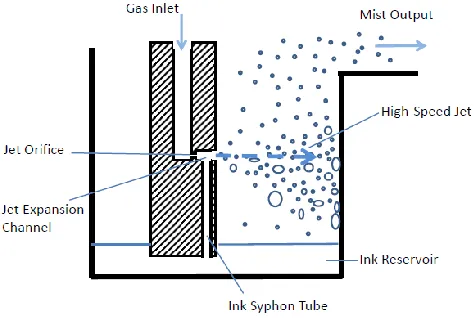
As described by May [1], the Collison nebulizer (schematically shown in Fig. 1) consists of a small jet orifice that produces a jet around sonic speed as compressed gas flows through it. Such a jet formed from compressed gas would expand in the jet expansion channel downstream of the jet orifice, creating a reduction of local static pressure (or “negative pressure”) to suck liquid ink through the ink syphon tube. Thus, the ink syphoned into the jet stream region can then form liquid sheets, filaments, and droplets under the strong shear of high-speed jet flow. No active liquid pump is used here, remarkably.
Fig. 1 Schematic of a typical configuration of the Collison nebulizer
However, the liquid droplets produced by such a blowing gas jet often have a very wide size distribution. To remove droplets larger than 5 m or so, the droplets carried by the jet flow are directed toward the wall of nebulizer chamber, where large droplets with sufficient mass are blown onto by inertial impaction. Only a small fraction (typically < 0.1%) of the liquid syphoned into jet stream can become fine enough
A Computational Analysis of Gas Jet Flow Effects on
Liquid Aspiration in the Collison Nebulizer
James Q. Feng
2 droplets (e.g., < 5 m) to escape impact and be carried by the gas flow as the output mist [1].
Because more than 99.9% of the liquid ink going through the atomization process is cycled back to the ink reservoir, the liquid aspiration rate through the ink syphon tube is expected to substantially influence the output mist density of the nebulizer. Sufficient liquid aspiration rate requires sufficient negative pressure in the jet expansion channel. For a given aspiration rate, an ink with higher viscosity needs stronger negative pressure. Thus, the value of negative pressure generated in the jet expansion channel by compressible gas jet flow becomes the subject of study in this paper.
B.Atomization Behavior of the Collison Nebulizer
Many applications desire high liquid mass output from the nebulizer, which is probably why the Collison nebulizer typically operates with a gas flow rate Q > 2000 sccm (per jet), through a jet orifice typically of diameter D = 0.35 mm. It has commonly observed that the liquid mass density in output mist (also known as the mist density) decreases with the gas flow rate, although the liquid mass output still increases for Q > 2000 sccm [1]. This fact suggests that beyond 2000 sccm the increase of liquid atomization rate cannot catch up the increase of gas flow rate.
In contrast, for Aerosol Jet® direct-write applications, the output mist density generated from its (Collison-type) pneumatic atomizer is much more relevant to the desired high printing throughput. Depending on ink materials, it has been found more often than not that the peak mist density is obtained at a gas flow rate around Q = 1200 sccm; further increasing the gas flow rate rather yields lower mist density. With more careful experimentations, most inks for Aerosol Jet® printing are found to yield mist output at a gas flow rate greater than Q = 600 sccm.
In the standard Collison nebulizer configuration, the atomization jet (as well as the jet expansion channel) is located about h = 20 mm above the liquid level in the ink reservoir (cf. Fig. 1). To bring ink through its syphon tube from the reservoir up to the jet stream for atomization, the pressure in jet expansion channel must be reduced to a level at least enough to overcome the hydrostatic pressure ink g h with ink denoting the ink density and g (= 9.81 m s
-2 ) the gravitational acceleration. Most metal nanoparticle inks for Aerosol Jet® in printing electronic devices often have ink about 2 g/cc. Thus the hydrostatic pressure ink g h may be estimated as about 400 Pa. In other words, the reduction of pressure (also known as the “negative pressure”) in jet expansion channel from the atomizer chamber pressure (which is usually very close to the ambient value, e.g., 105 Pa) must be greater than 400 Pa (plus or minus about 100 Pa due to the capillary effect depending on the contact angle and surface tension of the ink) at a gas flow rate of Q = 600 sccm.
When the volumetric flow rate Q of compressible gas flow is measured in units of “standard cubic centimeters per minute” (sccm), the actual volumetric flow rate varies with temperature but the mass flow rate remains as a constant. Thus, the value of U = 4 sQ / (D2) is a constant for given
Q and D, with and s denoting the actual density of gas and that under standard conditions at Ts = 273 K and Ps = 105 Pa, e.g., s = Ps / (RTs) = 1.276 kg/m
3
for dry air (which is about the same as the dry nitrogen typically used as the inert carrier gas in Aerosol Jet® systems). The value of the jet Reynolds number Re = UD / can be calculated as 1.464 Q / D with Q in units of sccm and D in millimeters assuming the dynamic viscosity of gas = 1.85 x 10⁻⁵ kg m-1 s-1 (at T = 300 K). Hence Re = 5018 with Q = 1200 sccm and D = 0.35 mm, while Re = 2509 for Q = 600 sccm.
C.The CFD Model
The mathematical model considered here is for fluid dynamics simulation of a compressible gas flowing from an inlet channel through a small jet orifice into a jet expansion channel of larger diameter and then into a much large atomization chamber with a solid wall at its end. For simplicity without loss of the essence of the problem, all the involved channels are arranged concentrically such that the computational domain becomes axisymmetric (with negligible effect of gravity in such a microscale gas flow).
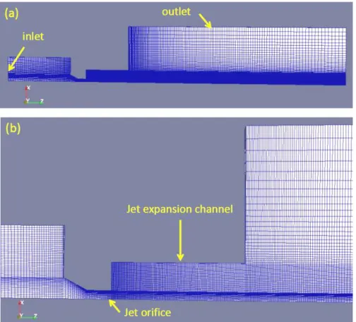
As a nominal model setting, the jet orifice has a diameter of D = 0.35 mm and the diameter and length of jet expansion channel are De = 1.5 mm and Le = 2.7 mm, to be consistent with the standard Collison nebulizer design [1]. To complete model construction, the computational domain also contains an entrance tube of 3 mm diameter upstream of the jet orifice and a large cylindrical chamber with diameter of 7 mm and length of 14 mm downstream of the jet expansion channel (as shown in Fig. 2).
Fig. 2 (a) Complete, and (b) regional details of the computational domain with a wedge type mesh for axisymmetric problem, generated
with the blockMesh utility
boundaries of the computational domain are treated as solid walls.
Among several choices, the steady compressible flow solver known as rhoSimpleFoam, available in the OpenFOAM® CFD Toolbox v.2.4.0 [6], is used for computing solutions of the Navier-Stokes equation system (which includes equations for conservations of mass, momentum, and energy, governing the flow of a fluid described by the ideal gas law and Fourier’s law of heat conduction with Sutherland’s law for dynamic viscosity). This solver also contains a variety of turbulence models. The 3D meshing utility blockMesh, included in the OpenFOAM® package, is used to generate mesh according to the computational domain (in Fig. 2).
The boundary conditions for flow velocity U, pressure p, and temperature T at solid walls are fixedValue (for U = 0), zeroGradient (for p), and fixedValue (T = 300K), at inlet flowRateInletVelocity (for U with a specified mass flow rate), zeroGradient (for p), and fixedValue (T = 300K), and at outlet pressureInletOuletVelocity (for U), fixedValue (for p = 105 Pa), and zeroGradient (for T), respectively.
Based on estimated values of the jet Reynolds number (e.g., ~2500 at Q = 600 sccm, etc.), the free jet flow out of the small orifice (with D = 0.35 mm) is expected to be turbulent [7, 8]. Thus some kind of turbulence model should be included in the present CFD model. For lack of better knowledge, a common k- model is used here based on Reynolds Averaged Navier-Stokes (RANS) equations, which is (among others) available in the rhoSimpleFoam solver.
III. RESULTS
It is usually difficult to obtain converged solutions by running the rhoSimpleFoam solver from a simple default initial condition. In the present work, the corresponding transient flow solver known as rhoPimpleFoam, also available in OpenFOAM®, is used for computing compressible flow solutions over certain time span to supply more reasonable initial conditions for the rhoSimpleFoam solver to compute the steady-state solutions.
A.The Nominal Case
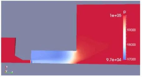
For the nominal case with jet orifice of D = 0.35 mm with a jet expansion channel of De = 1.5 mm and Le = 2.7 mm, the computed results of gas flow field in terms velocity magnitude |U| and pressure p with a gas flow rate of Q = 1200 sccm are shown in Fig. 3. At the exit of the jet orifice, the jet velocity can approach 246 m/s, corresponding to a Mach number Ma = 0.746. Then, the jet expands with velocity decreasing as it moves forward. A significant region of negative pressure P ~1524 Pa indeed appears in the jet expansion channel, providing the syphoning effect for liquid aspiration. Somehow the pressure field does not exhibit similar distribution structure as that of the flow velocity. The lowest pressure zone does not coincide with that of highest velocity as anticipated from Bernoulli’s principle.
The computed results of gas density and temperature T at Q = 1200 sccm are shown in Fig. 4. The peak value of gas density ( = 1.65 kg/m3) upstream to the jet orifice matches
that calculated for p = 1.425 x 10⁵ Pa and T = 300 K according to the ideal gas law for dry air (i.e., 1.655 kg/m3). The value minimum T (= 270 K) matches that calculated according to the standard 1D isentropic flow theory [9], i.e., T = 300/(1 + 0.2 Ma2), (with a specific heat ratio of 1.4 and Ma = 0.746, which yields 269.95 K). Both the field and T field in Fig. 4 display similar structures as that of the |U| field in Fig. 3, with slightly higher density and lower temperature in the high-speed jet velocity region.
Fig. 3 (a) The field of gas flow velocity magnitude |U| (m/s) and (b) pressure p (Pa) for the nominal case configuration at Q = 1200 sccm
Fig. 4 (a) The field of gas density (kg/m3), and (b) gas temperature T (K) for the nominal case configuration at Q = 1200 sccm
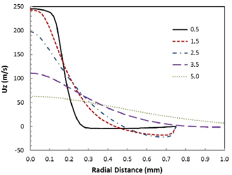
4 the edge of the plug flow profile diffuses out while the jet velocity declines with the axial distance from the jet orifice. For z < 2.7 mm (within the jet expansion channel), there is a back flow region (as indicated with negative Uz) near the channel wall surrounding the jet as a consequence of mass conservation. The back flow disappears as the free jet moves outside the jet expansion channel into the atomization chamber, where the jet stream widens with further reduced velocity due to viscous diffusion (as seen in experiments [7]).
Fig. 5 Radial profiles of axial velocity component Uz in the nominal configuration for Q = 1200 sccm at axial distance z = 0.5, 1.5, 2.5,
3.5, 5.0 mm from the exit of jet orifice
Corresponding to Fig. 5, the radial profiles of pressure (in units of bar) are plotted in Fig. 6. A generally positive pressure gradient in the axial direction is consistent with declining jet velocity with z, and the back flow shown in Fig. 5. Each curve shows that the gas pressure generally decreases from jet center with radial distance at a given axial distance z, with a minimum located close to the channel wall where the back flow magnitude is considerably large. So, the lowest pressure does not appear in the region of highest gas velocity at the jet center, according to an intuitive imagination based on Bernoulli’s principle. From the fluid dynamics point of view, an expanding gas jet flow is expected to relate to a decreasing pressure in the radial direction; a decreasing jet velocity with axial distance z should correspond to a positive pressure gradient with respect to z, i.e., dp/dz > 0. Due to viscous drag, the jet flow tends to bring more gas out of the jet expansion channel than what is supplied from the exit of jet orifice, which creates a reduced local pressure to drive the back flow for compensating the jet depleted gas. Thus, a region of negative pressure appears in the jet expansion channel.
Even out of the jet expansion channel at z = 3.5 and 5.0 mm, a negative pressure about 20 Pa appears near the radial distance r = 0.75 mm and about 5 Pa near r = 1.2 mm, respectively. Such a negative pressure around the jet was sometimes used to suck smoke generated by a nearby smoke wire for the jet flow visualization experiments [8]. Near the jet center, the pressure is higher at z = 3.5 mm with higher gas velocity than that at z = 5.0 mm, while the central pressure
generally exhibits lower value with higher jet speed inside the jet expansion channel.
Fig. 6 As Fig. 5 but for radial profiles of pressure p (in units of bar)
Table I shows the CFD results for maximum jet velocity Umax and its corresponding Mach number Mamax, the value of negative pressure P (defined as the pressure value at the wall of jet expansion channel 1.5 mm from the jet exit subtracted from the atomization chamber pressure 105 Pa = 1 bar), the gauge pressure upstream to the jet orifice Pg (= pmax – 1.0 bar where 1 bar = 105 Pa), and minimum gas temperature in the jet flow Tmin, at various gas flow rates.
TABLEI
COMPUTEDVALUESFORTHENOMINALCASE
Q (sccm) Umax (m/s) Mamax P (Pa) Pg (bar) Tmin (K)
600 136 0.397 378 0.111 291
900 194 0.576 862 0.241 281
1200 246 0.746 1524 0.425 270
1500 291 0.903 2218 0.662 258
1800 329 1.046 2755 0.927 246
Interestingly, with a gas flow rate of Q = 600 sccm the present CFD model indeed predicts a negative pressure of P ~ 380 Pa in most part of the jet expansion channel, consistent with expected minimum values estimated based on hydrostatic pressure and capillary effect as well as empirical knowledge. Consistent with the theoretical expectation as well as measurements of various pneumatic atomizers [1][4], the value of ‘air pressure’ Pg increases monotonically with the gas flow rate Q though the correlation is not exactly linear.
exit of the jet orifice. Interestingly, the 1D isentropic flow theory would suggest a local pressure of 3600 Pa below the ambient value.
Fig. 7 The pressure field for Q = 1800 sccm with Mamax = 1.046
Despite the fact that the gas jet flow simulated here may differ considerably from that of simplified flow case, the 1D isentropic flow theory [9], i.e., Tmin = 300 / (1 + 0.2 Ma
2 ) and P = [1 – (1 + Pg) / (1 + 0.2Ma2)3.5] x105, can predict Tmin quite accurately and P reasonably well for Ma < 1 based the computed values of Mamax and Pg given in Table I. For example, the value of P is calculated as 336, 891, 1508 and 2052 Pa for Q = 600, 900, 1200 and 1500 sccm, respectively. When Mamax > 1, the value of P calculated from the 1D formula is only consistent with the lowest pressure value associated with the shock wave, not the negative pressure in most part of the jet expansion channel for liquid aspiration.
B.Variations with Jet Orifice of D = 0.35 mm
If the nominal case configuration is modified with the diameter of jet expansion channel reduced to De = 1.0 mm (from the nominal 1.5 mm), the computed values of Umax, Mamax, P, Pg, and Tmin at various gas flow rates become those in Table II. Such a reduction of De tends to enhance P in the jet expansion channel by more than a factor of 3, with slightly increased jet velocity and Mamax at a given Q.
TABLEII
ASTABLEIBUTFORREDUCEDEXPANSIONCHANNELDIAMETER
Q (sccm) Umax (m/s) Mamax P (Pa) Pg (bar) Tmin (K)
600 138 0.403 1359 0.099 291
900 199 0.592 2904 0.221 280
1200 256 0.780 4946 0.401 267
1500 306 0.958 7377 0.639 253
1800 354 1.136 10052 1.017 241
In this case, the 1D isentropic flow theory would grossly overestimate the value of P based on the values of Mamax and Pg given in Table II. For example, the value of P would be calculated as 1732, 3675, 6266 and 9130 Pa for Q = 600, 900, 1200 and 1500 sccm, respectively (for Mamax < 1). Therefore, the 1D theory may be used for a rough sanity check of the CFD results, but should not be regarded as a reliable predictive tool with acceptable accuracy.
Conversely, with increasing De to 1.7 mm (from 1.5 mm)
the peak jet velocity for Q = 1200 sccm is reduced from 246 to 244 m/s with Mamax = 0.741, and P becomes 828 Pa, much lower than 1524 Pa with the nominal configuration.
The effect of varying the jet expansion channel length Le is examined by reducing Le from 2.7 to 2.2 mm, with computed results shown in Table III. Shortening the jet expansion channel length tends to reduce the magnitude of negative pressure. Conversely, increasing Le to 3.0 mm (with De = 1.5 mm) could increase P to 1987 Pa (with Mamax = 0.749, Pg = 0.423 bar) for Q = 1200 sccm.
TABLEIII
ASTABLEIBUTFORREDUCEDEXPANSIONCHANNELLENGTH
Q (sccm) Umax (m/s) Mamax P (Pa) Pg (bar) Tmin (K)
600 136 0.397 195 0.113 291
900 193 0.573 461 0.244 281
1200 245 0.741 839 0.429 270
1500 289 0.896 1221 0.666 258
1800 326 1.034 1516 0.928 247
The reason for enhanced negative pressure by shrinking De and increasing Le is simply that a narrower and longer channel corresponds to a greater pressure gradient for driving the same amount of back flow, to compensate the jet depleted gas in the jet expansion channel. But too narrow a jet expansion channel may introduce practical difficulties with its cleaning and maintenance.
Fig. 8 The pressure field for Q = 1800 sccm with Mamax = 1.054 in a jet expansion channel with diameter increasing from 1.0 to 1.5 mm
If the jet expansion channel is arranged to have a diverging expansion channel (as shown in Fig. 8), Table IV indicates that the negative pressure therein is generally enhanced in comparison with the nominal configuration. The magnitude of negative pressure is somewhere in between of that of Table I and Table II, not surprisingly.
TABLEIV
ASTABLEIBUTFORADIVERGINGEXPANSIONCHANNEL
Q (sccm) Umax (m/s) Mamax P (Pa) Pg (bar) Tmin (K)
600 136 0.398 464 0.110 291
900 194 0.577 1058 0.239 281
1200 247 0.750 1929 0.423 270
1500 293 0.909 2667 0.659 257
6 Changing the jet expansion channel from diverging (as in Fig. 8) to converging, e.g., with diameter gradually decreasing from 1.5 to 1.0 mm with the axial distance z, the values of Umax, Mamax, and P for Q = 1200 sccm become 253 m/s, 0.770, and 4863 Pa, respectively (approaching those corresponding values in Table II). Thus, the diameter of outlet of the jet expansion channel plays a more important role to influence the negative pressure magnitude, as expected from the fluid dynamics point of view.
It appears that the magnitude of negative pressure generally correlates with the value of Mamax of the jet flow. One of the effective ways to increase the Mach number at a given gas flow rate Q is to reduce the jet orifice size.
C.Effects of Reducing Jet Orifice to D = 0.25 mm
By reducing the diameter of jet orifice D to 0.25 mm (from the nominal 0.35 mm), the value of Mamax is expected to increase by a factor of two at a given gas flow rate, because the jet velocity is roughly given by 4Q/(D2) and (0.25/0.35)2 = 0.5102. The computed results are shown in Table V, for the nominal configuration of the Collison nebulizer only with the jet orifice reduced to D = 0.25 mm. Indeed the value of Mamax increases by about a factor of two for a corresponding value of Q compared to those with D = 0.35 mm. For example, with Q = 600 sccm the computed Mamax would be 0.741 and 0.745 for jet expansion channel with De = 0.15 and 0.10 mm (at Le = 2.7 mm), respectively.
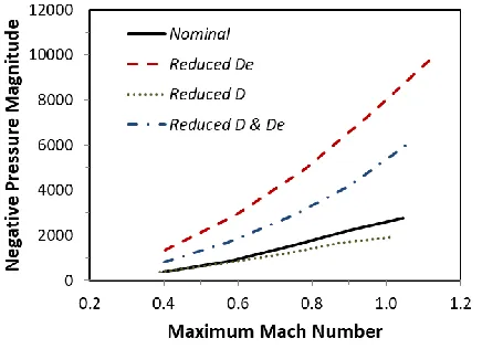
Fig. 9 The plot of negative pressure magnitude P versus maximum Mach number Mamax for the nominal case, for De reduced from 1.5 to 1.0 mm, for D reduced from 0.35 to 0.25 mm (while De = 1.5 mm),
and for De reduced from 1.5 to 1.0 mm (while D = 0.25 mm)
The general effects of varying D = 0.35 to 0.25 mm and P = 1.5 to 1.0 mm on P versus Mamax are shown in Fig. 9, with solid line denoting the nominal case (D = 0.35 mm and De = 1.5 mm with Le = 2.7 mm), dashed line for De reduced to 1.0 mm, dotted line for D reduced to 0.25 mm, and dash-dot line for De reduced to 1.0 mm while D = 0.25 mm. It becomes clear that the most effective way to significantly increase P is to shrink the diameter of jet expansion channel De, e.g., from 1.5 to 1.0 mm. While reducing the jet orifice diameter D from 0.35 to 0.25 mm can increase Mamax by about a factor of
two with a given gas flow rate Q, the magnitude of negative pressure at a given Mamax is somewhat reduced from that with D = 0.35 mm for the same jet expansion channel. Thus the ratio of De and D can be important, too. With De = 1.5 mm, De/D = 4.286 and 6.0 for D = 0.35 and 0.25 mm, consistent with the effect of enhancing P by reducing De/D (as suggested by Table II).
Moreover, the length of jet expansion channel Le also has a role to play to influence the magnitude of negative pressure P (as shown with Table III). For a case of D = 0.25, De = 1.0714, and Le = 1.9286 mm, the values of De/D and Le/D are kept the same as that in Table I, only with the jet orifice diameter D changed to 0.25 mm. The computed value of P then becomes 1412 Pa for Q = 600 sccm with Mamax = 0.744, quite close to 1524 Pa for a similar value of Mamax in Table I. Despite the similarity of geometric configuration, reducing the jet orifice diameter leads to a change of Reynolds number (i.e., Re = 3513 for D = 0.25 mm whereas Re = 5018 for D = 0.35 mm). Thus some difference in P between D = 0.25 and 0.35 mm is not surprising.
IV. DISCUSSION
From the presented CFD results, a general idea can be gained about the magnitude of negative pressure generated with the compressible gas jet flow in the jet expansion channel of a pneumatic atomizer (as variations of the Collison nebulizer). Whether the value of such a negative pressure P can account for the observed behavior of pneumatic atomization deserves an in-depth discussion.
According to the description of May [1] with measurements of a Collison nebulizer, the typical liquid aspiration rate is about Qink = 67 ml/min (per jet) for water. This requires an extra pressure difference of about 180 Pa over the ink syphon tube with a length of Ls = 20 mm and diameter of Ds = 1.5 mm, assuming a liquid viscosity of ink = 1.0 cp (= 0.001 Pa s) in the Poiseuille equation P = 128 ink Ls Qink / ( Ds4). Including the hydrostatic pressure (200 Pa for ink = 1.0 g/cc), a negative pressure of P = 380 Pa (probably with a gas flow rate of Q = 600 sccm) should be sufficient for syphoning water at a rate of 67 ml/min. But the typical gas flow rate used with the Collison nebulizer was Q > 2000 sccm [1], which is expected to produce much more negative pressure (e.g., P > 3000 Pa in view of Table I). Hence, a dynamic balance is expected between the liquid aspiration rate and the liquid removal rate due to shearing force from the blowing gas stream in the jet expansion channel. Some measurement data indeed show that asymptotic values of liquid aspiration rate seem to be approached with increasing air pressure Pg (or gas flow rate Q) for several “air-jet” nebulizers [4].
sccm (in view of Table I). In realistic atomizer operation, however, the flow field in jet expansion channel is not a single-phase gas flow as computed here; instead there is a two-phase liquid-gas flow. If we take into consideration of the fact that part of the jet expansion channel would be filled with the syphoned liquid, the channel volume for gas-phase flow is reduced and the channel diameter effectively shrinks in a dynamic process of liquid being syphoned in and blown out. Reduced diameter of jet expansion channel due to the liquid holdup in the jet expansion channel enhances the negative pressure for syphoning (as shown in Table II, etc.), to produce an appropriate liquid aspiration rate. Thus, a dynamic balance of liquid holdup can be imagined as the more liquid syphoned into the channel the more liquid will be blown out for atomization. The exact amount of liquid holdup and shape of the gas-liquid free surface in the jet expansion channel require a technically challenging multiphase free-surface flow simulation with very fine discretization meshes which is not pursued in the present study.
At the minimum gas flow rate (e.g., Q = 600 sccm or so) for atomization, the magnitude of negative pressure may only reach the threshold to bring liquid ink up to the jet expansion channel, with little extra for sustaining the expected liquid aspiration rate in the syphon tube. But as the liquid cumulates in the channel, the channel diameter shrinks and negative pressure increases, leading to greater liquid aspiration rate until a dynamic balance in the liquid holdup is accomplished.
The amount of liquid holdup in the jet expansion channel is expected to increase with the gas flow rate, up to a maximum amount. Beyond certain value of the gas flow rate, the maximum liquid aspiration rate is approached and then a maximum output mist density is obtained; further increasing the gas flow rate may effectively dilute the mist even with more liquid being atomized. This could explain why the mist density output from the Collison nebulizer typically goes up and then down with increasing the gas flow rate or gauge pressure Pg of the gas supply.
For Aerosol Jet® printing, the typical mist flow rate (through a single ink deposition nozzle) is less than 400 sccm, depending upon the nozzle size dictated by the desired print feature size. (To print fine feature about 10 m or less, the mist flow rate is usually less than 10 sccm with a deposition nozzle having a small outlet diameter of 100 m). But the gas flow rate for pneumatic atomizer to produce ink mist needs to be more than 600 sccm (and typically around Q = 1200 sccm for a maximized mist mass throughput with a given print feature size). Hence there is a substantial mismatch between the gas flow rate for ink atomization with the pneumatic atomizer and that of the mist flow for printing. Although such a mist flow rate mismatch can be solved by using a virtual impactor [2], reducing the gas flow rate for adequate ink atomization remains as a desired attribute for the pneumatic atomizer improvement.
According to the present study, reducing the jet orifice diameter (e.g., from D = 0.35 to 0.25 mm) can produce sufficient negative pressure in the jet expansion channel for ink aspiration at much reduced gas flow rate. But this
modification may require a reduction of the diameter of jet expansion channel, too. Smaller channel is expected to reduce the liquid ink hold up therein for the gas stream to blow out and atomize. On the other hand, for a given Mamax smaller jet orifice leads to a smaller amount of kinetic energy, which is often a key parameter for effective atomization [11] (because the physical process of atomization is in fact to convert part of the kinetic energy of gas jet flow into the surface energy of droplets). Therefore, the jet orifice diameter may not be reduced indefinitely for acceptable atomization performance; a minimum diameter is very likely to exist based on various practical considerations. Hence, more theoretical analysis and experimentation are required for optimizing the design of improved pneumatic atomizer for Aerosol Jet® printing as well as other applications.
V.SUMMARY
The results of CFD simulations in this work illustrate that the pressure distribution in the Collison nebulizer differs significantly from that of other fields with a clear characteristic structure, such as velocity, temperature, etc. A region of reduced pressure fills most of the jet expansion channel, creating a positive pressure gradient in the axial direction (i.e., dp/dz > 0) consistent with the sustained gas back flow surrounding the jet core in the jet expansion channel. Such a reduced pressure, or negative pressure, could serve as the driving force for syphoning liquid ink from the ink reservoir into the jet expansion channel for subsequent atomization, enabling the Collison nebulizer to operate without requiring an active liquid pump.
The magnitude of negative pressure for a given gas flow rate appears to be quite sensitive to the geometric parameters of jet expansion channel. Among others, shrinking channel diameter can significantly enhance the negative pressure for liquid aspiration. This revealed effect provides a logical explanation of the fact that the Collison nebulizer is quite capable of adequately atomizing liquids with a wide range of viscosity, even up to 1000 cp (= 1.0 Pa s). The CFD analysis presented here is intended to help guide future development of more efficient pneumatic atomizers, with compressible gas jet and associated negative pressure for liquid aspiration.
ACKNOWLEDGMENT
The author would like to thank Dr. Andreas Mack of TNO Heat Transfer and Fluid Dynamics (Netherlands) for friendly sharing his knowledge in compressible turbulent flow modeling, Mr. Dan Bachman and Mr. Dominick Carluccio of CH Technologies for carrying out intellectually inspiring experimental tests with various configurations of pneumatic nebulizers, and Dr. Mike Renn as well as many other Optomec colleagues for valuable technical discussion.
REFERENCES
[1] K.R. May, “The Collison nebulizer: description, performance and application,” J. Aerosol Sci., vol. 4, pp. 235–243, May 1973.
[2] https://www.optomec.com/printed-electronics/aerosol-jet-technology/
8 [3] J.Q. Feng, “Multiphase flow analysis of mist transport behavior in
Aerosol Jet® system,” Int. J. Comput. Meth. and Exp. Meas., vol. 6, no. 1, pp. 23–34, 2018.
[4] R.W. Niven and J.D. Brain, “Some functional aspects of air-jet nebulizers,” Int. J. Parmaceut., vol. 104, pp. 73–85, 1994.
[5] D.R. Hess, “Nebulizers: Principles and performance,” Respiratiory Care, vol. 45, no. 6, pp. 609–622, June 2000.
[6] https://github.com/OpenFOAM/OpenFOAM-2.4.x (12/7/2017)
[7] P. O’Neill, J. Soria, and D. Honnery, “The stability of low Reynolds number round jets,” Exp. Fluids, vol. 36 (3), pp. 473–483, 2004. [8] C. Gau, C.H. Shen, and Z.B. Wang, “Peculiar phenomenon of
micro-free-jet flow,” Phys. Fluids, vol. 21, 092001, 2009.
[9] https://web.stanford.edu/~cantwell/AA210A_Course_Material/
(12/7/2017).
[10] J.Q. Feng, “Sessile drop deformations under an impinging jet,” Theor. Comput. Fluid Dyn., vol. 29, issue 4, pp. 277–290, August 2015. [11] A. H. Lefebvre, Atomization and Sprays. New York: Hemisphere, 1989,