Universal Compensation Method for Trans-Directional Coupled-Line
Based Planar Balun with Connecting Segment
Xiao Jia, Shaojun Fang, Hongmei Liu*, and Zhongbao Wang
Abstract—In the paper, a universal compensation method is presented to improve the imbalance of a trans-directional coupled-line (TRD-CL) based balun caused by the inevitable physical separation between the TRD-CLs. Using this method, the input mismatch and output imbalance can be effectively solved. Moreover, since the compensation is achieved by shortening the two TRD-CLs instead of adding additional stubs, size miniaturization is maintained. Design formulas are derived using the signal flowchart and even-odd mode analysis. A prototype operating at 1.6 GHz is also designed and measured to verify the proposed method.
1. INTRODUCTION
Baluns, which transform unbalanced signals to balanced signals, are key components in the applications of mixers, doublers, and balun filters [1–3]. Antenna matching is also an important application for baluns, especially balanced antennas [4–6]. Among them, Marchand baluns are popular configurations due to the simplicity and wideband performance. In recent years, Marchand baluns have gained great progress in many aspects, including impedance transformation [7, 8], isolation circuit [9], and miniaturization [10, 11]. However, since the two short-circuited terminals of a Marchand balun should be connected to the ground by via-holes, the production is complicated, and parasitic inductances are induced. Besides, single-layer coupled line based Marchand balun is hard to realize due to the technology limitation for tight couplings. Regarding the above problems, a new type of planar balun composed of two trans-directional coupled lines (TRD-CLs) is proposed [12]. Compared with a coupled line based Marchand balun, the need for tight coupled lines and via-holes is avoided.
Similar to Marchand balun, a connecting segment is also needed by the TRD-CL based planar balun in practice, which deteriorates the input match and output balance. However, in [12], the influence of the connecting segment is not considered, and no compensation technique is introduced. Although a number of researches allowing for the compensation of the connecting segment have been reported [13–15], they are all for Marchand baluns and are not suitable for TRD-CL based planar baluns.
In this paper, a universal compensation method for TRD-CL based planar baluns is proposed. By simply shortening the electrical length of the TRD-CL with recalculated even- and odd-mode impedances, the input mismatch and output imbalance caused by the connecting segment can be processed. In Section 2, a complete set of design equations are derived with signal flowchart and even-odd mode theory. In Section 3, compensated and uncompensated baluns are compared, and a prototype operating at 1.6 GHz is designed as verification, followed by a conclusion in Section 4.
2. THEORETICAL ANALYSIS
Figure 1 shows the schematic of a TRD-CL based planar balun with a connecting segment inserted (electrical length ofθx). Each of the TRD-CLs has an electrical length ofθc(θc <90◦). The equivalent
Received 30 January 2019, Accepted 28 March 2019, Scheduled 10 April 2019 * Corresponding author: Hongmei Liu ([email protected]).
Figure 1. Schematic of the proposed balun with a connecting segment.
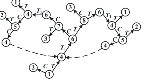
Figure 2. Signal flowchart of the proposed balun at port 1.
even- and odd-mode electrical lengths of the TRD-CL are defined as θe and θo, respectively, while the equivalent even- and odd-mode characteristic impedances are named as Z0e and Z0o, respectively. The characteristic impedance of the connecting segment is defined as Z0, and it is equal to the port impedance of the TRD-CLs for impedance matching.
Signal flowchart is utilized to derive S-parameters of the planar balun. For convenience, the transmission and coupling coefficient of the TRD-CL are denoted asT andC, respectively. T1represents the transmission coefficient of the connecting segment. Fig. 2 shows the signal flowchart when port 1 is excited, and the numbers 4–8 are the nodes marked in Fig. 1. According to Fig. 2, S-parameters of the balun for port 1 excitation can be obtained.
S11(Balun) =
(C2+T2)T2T12 1−C4T2
1 −C2T2T12
(1a)
S21(Balun) = C+ C 3T2T2
1 +CT4T12 1−C4T2
1 −C2T2T12
(1b)
S31(Balun) =
2CT2T1 1−C4T2
1 −C2T2T12
(1c)
whereT1 =e−jθx.
In order to get perfect impedance match and balanced outputs, the following relations should be satisfied:
S11(Balun) = 0 (2a)
S21(Balun) = −S31(Balun) (2b)
Substituting Eq. (1a) into Eq. (2a) derives:
C2+T2= 0 (3)
Solving Eq. (2b) with Eqs. (1b), (1c), and (3), the transmission and coupling coefficient of the TRD-CL can be obtained:
C = √
2 2 e
T = −j √
2 2 e
jθx2 (4b)
It is found from Eq. (4) that to realize perfect impedance match and balanced outputs (connecting segment inserted), the coupling of the TRD-CL should be 3 dB, and the phase difference between the coupled and through ports should be 90◦. Based on Eq. (4) and the operating condition of a TRD coupler [16], S-parameters of the shortened TRD-CL are:
S11(TRD) = 0 (5a)
S51(TRD) = 0 (5b)
S41(TRD) = T =−j √
2 2 e
jθx2 (5c)
S21(TRD) = C= √
2 2 e
jθx2 (5d)
Here, the subscripts are corresponding to the nodes marked in Fig. 1. S-parameters of the coupler can also be expressed using Eq. (6) according to the even-odd mode theory [17]:
S11(TRD) = S
11e+S11o
2 (6a)
S51(TRD) =
S21e+S21o
2 (6b)
S41(TRD) = S
21e−S21o
2 (6c)
S21(TRD) =
S11e−S11o
2 (6d)
where
S11{e,o} =
j sinθ{e,o}Z0{e,o}/Z0−Z0/Z0{e,o}
2 cosθ{e,o}+ j sinθ{e,o}Z0{e,o}/Z0+Z0/Z0{e,o}
(7a)
S21{e,o} =
2
2 cosθ{e,o}+ j sinθ{e,o}Z0{e,o}/Z0+Z0/Z0{e,o}
(7b)
Thus, the equivalent even- and odd-mode electrical lengths and characteristic impedances can be obtained by substituting Eq. (6) into Eq. (5).
θe = cos−1
√
2 sinθx 2
(8a)
θo = cos−1
√
2 sinθx 2
+ (2n−1)π (8b)
Z0e = Z0
√
2 cosθx 2 + 1 √
2 cosθx 2 −1
(8c)
Z0o = Z0
√
2 cosθx 2 −1 √
2 cosθx 2 + 1
(8d)
3. EXPERIMENTAL RESULTS
To validate the proposed compensation theory, a 1.6-GHz planar balun based on the TRD-CL reported in [18] is designed, as shown in Fig. 3. It is noted that the proposed compensation method can be applied to arbitrary TRD-CL based planar balun regardless of the practical implementations. Zce and
Zco are the even- and odd-mode characteristic impedances of the CL, while θc is the electrical length
of the CL. The values of the shunt capacitors are C1 and C2. According to Eq. (8) and the design equations for the TRD-CL in [10], circuit parameters of the designed balun with connecting segments of 10◦ and 20◦ are calculated, as listed in Table 1.
Figure 3. Schematic of the compensated planar balun.
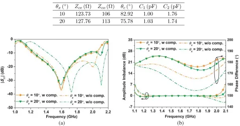
Table 1. Design data of the balun prototype.
θx(◦) Zce(Ω) Zco(Ω) θc(◦) C1(pF) C2(pF)
10 123.73 106 82.92 1.00 1.76
20 127.76 113 75.78 1.03 1.74
(a) (b)
Figure 4. Theory results of the planar balun with or without compensation. (a) Return loss. (b) Amplitude imbalance and phase difference.
Figure 4 shows theory results of the designed compensated balun. For comparison, the results of the uncompensated TRD-CL based planar balun are also calculated and plotted in Fig. 4 (short dash line). It can be clearly seen that the compensation method dramatically improves the performance of the planar balun including the input match and output balance. It is noteworthy that the phase imbalance of the uncompensated balun deteriorates sharply when the electrical length of the inserted connecting segment increases, while the compensation method deals with this problem well. Thus, the theory and approach described in Section 2 are confirmed to be correct and effective.
A prototype with a connecting segment of 10◦ was fabricated on an F4B substrate (εr = 3.2, tanδ = 0.003, h = 1.5 mm). Fig. 5 shows the layout and photograph of the prototype. The main optimized dimensions are: w1 = 0.65 mm, s1 = 3.1 mm, l1 = 27.6 mm, w2 = 3.6 mm, l2 = 8 mm,
(a) (b)
Figure 5. Photograph of the proposed balun. (a) Layout. (b) Fabricated prototype.
(a) (b)
(c)
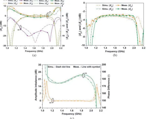
Figure 6. Simulated and measured results of the prototype. (a) |S11|,|S22|, |S33|and |S32|. (b) |S21| and |S31|. (c) Amplitude imbalance and phase difference.
ports 2 and 3. As a three-port network, the balun cannot be lossless, reciprocal, and matched at all ports [17]. Thus, mismatching at ports 2 and 3 is revealed from Fig. 6(a). To achieve a perfect match at all ports, an additional isolation circuit is needed [9]. Figs. 6(b) and (c) show the output ports amplitude and phase differences of the proposed balun. From 1.24 GHz to 2.01 GHz, the measured|S21| and|S31|are in the range of 3.2±0.5 dB and 3.1±0.3 dB, respectively, while the measured output ports amplitude imbalance and phase difference are within ±0.5 dB and 180◦±6◦, respectively.
4. CONCLUSION
In the paper, a general compensation method for TRD-CL based planar balun has been developed and analyzed. It processes the input mismatch and output imbalance caused by the connecting segment. To verify the proposed compensation theory, a planar balun operating at 1.6 GHz is designed and fabricated. The effectiveness of the proposed method has been proved by the measured results.
ACKNOWLEDGMENT
This work was supported by the National Natural Science Foundation of China (Grant Nos. 61571075, 51809030 and 61871417), the China Post-Doctoral Science Foundation (Grant No. 2017M611210), the Doctor Startup Foundation of Liaoning Province (Grant No. 20170520150), and the Fundamental Research Funds for the Central Universities (Grant Nos. 3132019211 and 3132019219).
REFERENCES
1. Tseng, S. C., C. Meng, C. Chang, C. Wu, and G. Huang, “Monolithic broadband Gilbert micromixer with an integrated Marchand balun using standard silicon IC process,” IEEE Transactions on Microwave Theory and Techniques, Vol. 54, No. 12, 4362–4371, 2006.
2. Lai, Y., C. Chen, and Y. Wang, “Compact doubler with simple harmonic suppression and gain-compensation functions,”IEEE Microwave and Wireless Components Letters, Vol. 21, No. 7, 371– 373, 2011.
3. Yeung, L. K. and K. Wu, “A dual-band coupled-line balun filter,”IEEE Transactions on Microwave Theory and Techniques, Vol. 55, No. 11, 2406–2411, 2007.
4. Lin, S., J. Wang, Y. Deng, and G. Zhang, “A new compact ultra-wideband balun for printed balanced antennas,” Journal of Electromagnetic Waves and Applications, Vol. 29, No. 12, 1570– 1579, 2019.
5. S´anchez, A. M., M. Rib´o, L. Pradell, J. Anguera, and A. And´ujar, “CPW balun for printed balanced antennas,”Electronics Letters, Vol. 50, No. 11, 785–786, 2014.
6. Zhang, G., J. Wang, and W. Wu, “Wideband balun bandpass filter explored for a balanced dipole antenna with high selectivity,” Electronics Letters, Vol. 52, No. 13, 1153–1155, 2016.
7. Ang, K. S. and I. D. Robertson, “Analysis and design of impedance-transforming planar Marchand baluns,” IEEE Transactions on Microwave Theory and Techniques, Vol. 49, No. 2, 402–406, 2001. 8. Ahn, H. and S. Nam, “New design formulas for impedance-transforming 3-dB Marchand baluns,”
IEEE Transactions on Microwave Theory and Techniques, Vol. 59, No. 11, 2816–2823, 2011. 9. Ahn, H. and T. Itoh, “New isolation circuits of compact impedance-transforming 3-dB baluns
for theoretically perfect isolation and matching,” IEEE Transactions on Microwave Theory and Techniques, Vol. 58, No. 12, 3892–3902, 2010.
10. Ang, K. S., Y. C. Leong, and C. H. Lee, “Analysis and design of miniaturized lumped-distributed impedance-transforming baluns,” IEEE Transactions on Microwave Theory and Techniques, Vol. 51, No. 3, 1009–1017, 2003.
12. Shie, C., J. Cheng, S. Chou, and Y. Chiang, “Design of a new type planar balun by using trans-directional couplers,” IEEE Transactions on Microwave Theory and Techniques, Vol. 60, No. 3, 471–476, 2012.
13. Ma, T., C. Wang, and C. Lai, “Miniaturized distributed Marchand balun using coupled synthesized CPWs,”IEEE Microwave and Wireless Components Letters, Vol. 21, No. 4, 188–190, 2011. 14. Lin, C., C. Wu, G. Zhou, and T. Ma, “General compensation method for a Marchand balunwith
an arbitrary connecting segment between the balance ports,” IEEE Transactions on Microwave Theory and Techniques, Vol. 61, No. 8, 2821–2830, 2013.
15. Ahn, H. and M. M. Tentzeris, “Novel generic asymmetric and symmetric equivalent circuits of 90◦ coupled transmission-line sections applicable to Marchand baluns,” IEEE Transactions on Microwave Theory and Techniques, Vol. 65, No. 3, 746–760, 2017.
16. Shie, C., J. Cheng, S. Chou, and Y. Chiang, “Transdirectional coupled-line couplers implemented by periodical shunt capacitors,”IEEE Transactions on Microwave Theory and Techniques, Vol. 57, No. 12, 2981–2988, 2009.
17. Pozar, D., Microwave Engineering, 3rd Edition, Wiley, New York, 2005.