Performance Analysis of Refined Induction Motor Models
Considering Iron Loss
Wan Jun Yin1, 2 and Tao Wen1, *
Abstract—In the applications such as induction motor efficiency optimization and electric vehicle speed control, the influence of the iron loss cannot be ignored. In order to improve the running efficiency of induction motor, the ordinary differential equations (ODE) and difference equations (DE) of induction motors considering iron loss have been established. The results show that the proposed refined ordinary differential equations and difference equations of induction motors considering iron loss and its simulation models are believable, and simulated and experiment results have demonstrated that the models perform well.
1. INTRODUCTION
Among various types of AC motors, induction motors, especially squirrel cage motors, are most commonly used in industry due to their economy, reliability, and durability. However, the research on the establishment and control of motor model is often considered ideal, without considering the iron loss. In practice, iron loss resistance is a function of frequency, and the equivalent magnetization reactance is also a variable value and a function of main magnetic flux [1, 2]. In order to control it accurately, it is necessary to study the simulation of motor control considering the actual situation. Although the development of variable frequency speed regulation technology has greatly reduced the losses of induction motors, the problem of low light load operation efficiency still exists. Today, energy problem is becoming more and more serious. It is of great significance to study the energy saving problem of variable frequency speed regulating induction motor under light load and improve its operation efficiency for saving energy and controlling environmental pollution. The mathematical models of ordinary differential equation and difference equation of induction motor considering the effect of equivalent resistance of iron loss are established.
Because the states and parameters are separated clearly in the ODE representation of the induction motor mathematical model, establishing a parameter variable simulation model is very easy [3–7], and the parameter can be changed during the simulation in arbitrary form.
2. ODE AND DE OF INDUCTION MOTORS CONSIDERING IRON LOSS
2.1. ODE of Induction Motors Considering Iron Loss
The equivalent Circuit of Induction Motor Considering Iron Loss underdqAxis of Synchronous Rotating Coordinate System is shown in Fig. 1.
Received 16 November 2019, Accepted 5 June 2019, Scheduled 17 June 2019
* Corresponding author: Tao Wen ([email protected]).
1?, School of Mechano-Electronic Engineering, Xidian University, Xi’an 710071, P. R. China. 2 Sichuan Vocational College of
Figure 1. Equivalent circuit of induction motor considering iron loss [1].
Based on Fig. 1 according to the Kirchhoff’s law, the voltage equations and current equations of the iron loss equivalent branch are as follows.
⎧ ⎪ ⎪ ⎪ ⎪ ⎪ ⎨ ⎪ ⎪ ⎪ ⎪ ⎪ ⎩
Lmdidm
dt −ωeLmiqm =idF eRF e Lmdiqm
dt +ωeLmidm=iqF eRF e ids+idr =idm+idF e
iqs+iqr =iqm+iqF e
(1)
the stator side and rotor side voltage equations are given as follows.
⎧ ⎪ ⎪ ⎪ ⎪ ⎪ ⎪ ⎪ ⎪ ⎪ ⎨ ⎪ ⎪ ⎪ ⎪ ⎪ ⎪ ⎪ ⎪ ⎪ ⎩
Rsids−ωeLσsiqs+Lσsdidtds +idF eRF e=uds
Rsiqs−ωeLσsiqs+Lσsdidtqs +iqF eRF e=uqs
Rridr−ωeLσriqr+Lσrdidtdr +Lmdidtdm −ωeLmiqm+ωrψdr = 0
Rriqr−ωeLσriqr+Lσrdidtqr +Lmdidtqm +ωeLmidm+ωrψdr = 0
(2)
whereids andiqs are thed-axis andq-axis stator currents;RF eis the equivalent iron loss resistance; ωe is the power angle frequency;ωr is the rotor electrical angular frequency;idmandiqm are thed-axis and
q-axis magnetizing currents, A; uds and uqs are the d-axis and q-axis stator voltages; ψdr and ψqr are thed-axis andq-axis rotor flux linkages; Lσs is the stator leakage inductance; Lσr is the rotor leakage inductances; Lm is the mutual inductance; Rs is the stator resistance;Rr is the rotor resistance.
ODE of the induction motor considering the iron loss is as follows.
⎧ ⎪ ⎪ ⎪ ⎪ ⎪ ⎪ ⎪ ⎪ ⎪ ⎪ ⎪ ⎪ ⎪ ⎪ ⎪ ⎪ ⎪ ⎪ ⎪ ⎨ ⎪ ⎪ ⎪ ⎪ ⎪ ⎪ ⎪ ⎪ ⎪ ⎪ ⎪ ⎪ ⎪ ⎪ ⎪ ⎪ ⎪ ⎪ ⎪ ⎩
−(Rs+RF e)ids
Lσs
+ωeiqs+LLrRF eidm σsLσr −
RF eψdr
LσsLσr + uds
Lσs
= dids
dt
−ωeids−
(Rs+RF e)iqs
Lσs
+LrRF eiqm
LσsLσr −
RF eψdr
LσsLσr + uqs
Lσs
= diqs
dt RF eids
Lσs
+ωeiqm−LrRF eidm
LmLσr
+RF eψdr
LmLσr
= didm
dt RF eiqs
Lσs −ωeidm−
LrRF eiqm
LmLσr
+RF eψqr
LmLσr
= diqm
dt LmRridm
Lσr −
LmRr
LrLσr +Rr
Lr
ψdr+ (ωe−ωr)ψqr= dψdr
dt LmRriqm
Lσr −
LmRr
LrLσr +Rr
Lr
ψqr+ (ωe−ωr)ψdr = dψdtqr
T e= P Lm
Lσr
(iqmψdr−idmψqr) (4)
dωr
dt = P
J (Te−TL) (5)
whereLs is the stator inductance,Lr the rotor inductances, TL the load torque,P the number of pole pairs, and J the inertia moment.
2.2. DE of Induction Motors Considering Iron Loss
Similarly, the difference equations can be obtained from ordinary differential equations
⎧ ⎪ ⎪ ⎪ ⎪ ⎪ ⎪ ⎪ ⎪ ⎪ ⎪ ⎪ ⎪ ⎪ ⎪ ⎪ ⎪ ⎪ ⎪ ⎪ ⎪ ⎪ ⎨ ⎪ ⎪ ⎪ ⎪ ⎪ ⎪ ⎪ ⎪ ⎪ ⎪ ⎪ ⎪ ⎪ ⎪ ⎪ ⎪ ⎪ ⎪ ⎪ ⎪ ⎪ ⎩
ids(k+ 1) =
1−(Rs−RF e)T
Lσs
ids(k) +T ωe(k)iqs(k) + T uds (k)
Lσs
+LrRF eT idm(k)
LσsLσr −
RF eT
LσsLσrψdr
iqs(k+ 1) =
1−(Rs−RF e)T
Lσs
iqs(k)−T ωe(k)ids(k) +T uqs (k)
Lσs
+LrRF eT iqm(k)
LσsLσr −
RF eT
LσsLσrψqr
idm(k+ 1) =
1−LrRF eT
LmLσs
idm(k) +T ωe(k)iqm(k) + RF eT ids (k)
Lm −
RF eT
LmLσrψdr (k)
iqm(k+ 1) =
1−LrRF eT
LmLσr
iqm(k)−T ωe(k)idm(k) +RF eT iqs (k)
Lm −
RF eT
LmLσrψqr (k)
ψdr(k+ 1) =
1−T
LmRr
LrLσr +Rr
Lr ψdr
(k) +LmRrT idm(k)
Lσr
+T(ωe(k)−ωr(k))ψqr(k)
ψqr(k+ 1) =
1−T
LmRr
LrLσr + Rr
Lr ψqr
(k) +LmRrT iqm(k)
Lσr −T
(ωe(k)−ωr(k))ψqr(k)
(6) whereT is the sampling period. The torque equation and motion equation are as follows
T e(k) = P Lm
Lσr
(iqm(k)ψdr(k)−idm(k)ψqr(k)) (7)
ωr(k+ 1) = (T e(k)−TL(k))P T
J +ωr(k) (8)
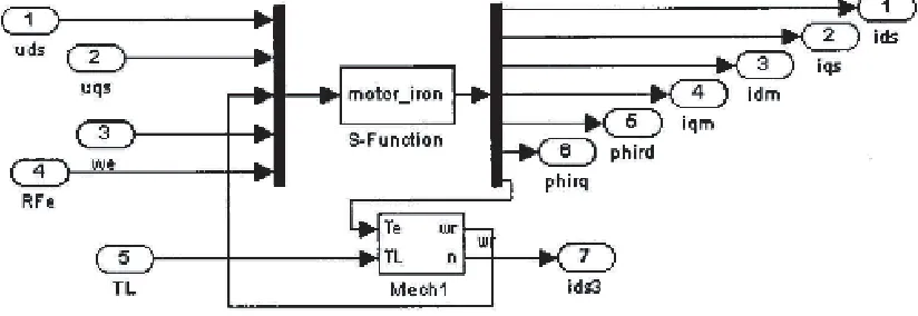
3. BUILDING SIMULATION MODEL IN MATLAB
Matlab is very popular simulation softwares in the power electronics fields [4–11]. In order to verify the correctness of the induction motor model considering iron loss, a simulation model as shown in Fig. 2 is established.
The simulation key C code is as follows: A11=-(Rs+RFe)/LIs;
A13=(Lr*RFe)/(LIs*LIr); A15=-RFe/(LIs*LIr); A33=-(Lr*RFe)/(Lm*LIr); A35=RFe/(Lm*LIr); A53=(Lm*Rr)/LIr;
A55=-((Lm*Rr)/(Lr*LIr)+(Rr/Lr));
x1=ids+(A11*ids+We*iqs+A13*idm+A15*Psidr+Ud/LIs)*delt; x2=iqs+(A11*iqs-We*ids+A13*iqm+A15*Psiqr+Uq/LIs)*delt; x3=idm+((RFe/Lm)*ids+A33*idm+We*iqm+A35*Psidr)*delt; x4=iqm+((RFe/Lm)*iqs+A33*iqm-We*idm+A35*Psiqr)*delt; x5=Psidr+(A53*idm+A55*Psidr+(We-Wr)*Psiqr)*delt; x6=Psiqr+(A53*iqm+A55*Psiqr+(-(We-Wr))*Psidr)*delt; ids=x1,iqs=x2,idm=x3,iqm=x4,Psidr=x5,Psiqr=x6; Te=((pm*Lm)/LIR)*(iqm*psidr-idm*psiqr);
Wr=Wr+(((Te-TL)*pm)/J)*delt n=30*Wr/(pm*3.1415926);
4. MODEL VALIDATION
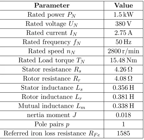
In order to verify the correctness of the proposed user-defined simulation models established, the models are compared with the library model provided by Matlab, and a induction motor is employed in the experiments. The parameters are given in Table 1.
Table 1. Induction motor parameters comparison.
Parameter Value
Rated power PN 1.5 kW Rated voltage UN 380 V
Rated currentIN 2.75 A Rated frequencyfN 50 Hz
Rated speed nN 2800 r/min Rated Load torqueTN 15.48 Nm
Stator resistance Rs 4.26 Ω Rotor resistance Rr 4.08 Ω Stator inductanceLs 0.356 H Rotor inductance Lr 0.381 H Mutual inductance Lm 0.338 H nertia moment J 0.018
Pole pairsp 1
Referred iron loss resistance RF e 1585
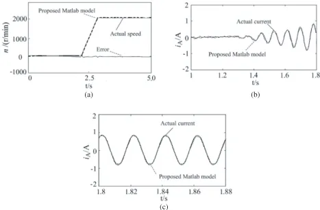
(a) (b)
(c)
Figure 3. Comparison between numerical solution of proposed simulation model and actual operation data of induction motor. (a) Speed wave forms. (b) Current wave forms comparison when induction motor starts. (c) Current wave forms comparison at steady state.
5. CONCLUSION
In this paper, the ordinary differential equation and difference equation models of induction motor considering iron loss are established and compared with MATLAB motor simulation model. The simulation results verify the accuracy of the model.
In future work, we will explore a simpler and more accurate induction motor model for the purpose of improving the operation efficiency of the motor.
ACKNOWLEDGMENT
This work is partially supported by the Key Program of Guangyuan Municipal Science and Technology Project (2018ZCZDYF016). The authors would like to express their sincere thanks to the referees for their valuable suggestions and comments.
REFERENCES
1. Li, J., F. F. Xiao, and S. Q. Zhang, “Simplified loss model control efficiency optimization algorithm for vector control induction motor drives,” IECON 2017 — 43rd Annual Conference of the IEEE Industrial Electronics Society, 5178–5183, Beijing, 2017.
3. Li, Z., Y. Jiang, and Q. Guo, “Multi-dimensional variational mode decomposition for bearing-crack detection in wind turbines with large driving-speed variations,”Renewable Energy, Vol. 116, Part B, 55–73, 2016, DOI: 10.1016/j.renene.2016.12.013.
4. Glowacz, A., “Acoustic based fault diagnosis of three-phase induction motor,” Applied Acoustics, Vol. 137, 82–89, 2018, DOI:10.1016/j.apacoust.2018.03.010.
5. Werner, U., “Vibration control of large induction motors using actuators between motor feet and steel frame,” Mechanical Systems and Signal Processing, Vol. 112, 319–342, 2018, DOI: 10.1016/j.ymssp.2018.04.033.
6. Caesarendra, W. A., “Review of feature extraction methods in vibration-based condition monitoring and its application for degradation trend estimation of low-speed slew bearing,” Machines, Vol. 5, No. 4, 2017, DOI:10.3390/machines5040021.
7. Glowacz, A., “Acoustic-based fault diagnosis of commutator,” Motor Electronics, Vol. 7, No. 11, 2018, DOI: 10.3390/electronics7110299.
8. Singh, G., “Detection of half broken rotor bar fault in VFD driven induction motor drive using motor square,” Mechanical Systems and Signal Processing, Vol. 110, 333–348, 2018, DOI: 10.1016/j.yrrissp.2018.03.001.
9. Pang, B., G. Tang, and T. Tian, “Rolling bearing fault diagnosis based on an improved HTT transform,”Sensors, Vol. 18, No. 4, 2018, DOI: 10.3390/s18041203.
10. Glowacz, A. and W. Glowacz, “Vibration-based fault diagnosis of commutator,” Motor Shock and Vibration, Vol. 2018, Article ID 7460419, 10 pages, 2018, DOI: 10.1155/2018/7460419.
![Figure 1. Equivalent circuit of induction motor considering iron loss [1].](https://thumb-us.123doks.com/thumbv2/123dok_us/7733728.1266335/2.612.186.432.75.227/figure-equivalent-circuit-induction-motor-considering-iron-loss.webp)