Improvement In Active Filter Capabilities Of Doubly Fed Induction
Generator Using Fuzzy Logic Controller
Manchikanti Prashanthi & Dr.Gopala Venu Madhav
1M.Tech(student), ANURAG Group of Institutions(Formerly known as CVSR College of Engineering (Autonomous) Affiliated
to JNTUH, Hyderabad, Telangana, India.
2Professor, ANURAG Group of Institutions(Formerly known as CVSR College of Engineering(Autonomous) Affiliated to
JNTUH, Hyderabad, Telangana, India.
Abstract -This paper deals with improvement in Doubly Fed Induction Generator (DFIG) by using FLC based on control of Grid-Side Converter (GSC).GSC does mainly two things which is are very useful to the system to maintain stability: One is Slip power transfer and the other is supply of harmonics which is useful to mitigate the harmonics produced due to nonlinear loads at PCC. The Rotor-Side Converter (RSC) mainly does the power extraction which is called MPPT (Maximum Power Point Tracking) and also for supplying sufficient reactive power to DFIG. In this paper, FLC is used instead of using other controllers because it is best acceptable for the animal controlling mechanism, accouterment the operation of making decisions with experts. This Wind Energy Conversion Arrangement (WECS) acts as a STATCOM for giving harmonics, even though wind turbine not able to operate/shutdown condition. GSC and RSC control algorithms are explained in brief. The DFIG which is based on WECS is explained using the MATLAB/Simulink. By application of FLC for a nonlinear arrangement allows reducing the uncertain effects developed at nonlinear loads also improves the efficiency. The control action for DFIG based WECS is analyzed by simulation results.
Key Terms - Doubly Fed Induction Generator, Integrated Active Filter, Fuzzy Logic Controller, Nonlinear Load, Power Quality, Wind Energy Conversion System.
I.INTRODUCTION
With raise in population and industrialization, the power demand consumes been increased considerably. Though, the renewable sources of energy like oil, coal and gas are limited in nature. At the moment conventional sources are very important [1]. These are mainly used since it is apt for nature and it will not harm any environment. [2]. since the technical enhancements, the price of wind energy generated is analogous to renewable sources. Nowadays, several load area units are powered by conventional sources and controlling action is doubly using the Fuzzy Logic Controller.
With the advanced power electronic devices, machine can run at adaptable speeds. DFIG is chosen due to its low price compared to all other wind turbines operated at different speeds. One other advantage of Double Fed Induction machine is the maximum energy output, minimum convertor rating, and better utilization of generators.
The better damping performance at weak grid is also provided by DFIG. The reactive power and active power is received separately with the decoupled vector control
algorithm the vector control algorithm of system is commonly apprehended through synchronously revolving reference frame concerned with voltage axis or with flux axis. Rotor-Side Convertor (RSC) controlling action is applied by voltage-oriented reference scheme. The requirements for Grid side connections and action of wind sources are discussed.
DFIG response is dependent ofWind Energy Conversion System (WECS) with respect to grid disorder. Since wind diffusion in the grid becomes significant, the usage of different speed WECS for supplementary jobs like power smoothening and harmonic alleviation are compulsory added to its power extraction. It is achieved by summing of super magnetic energy storage systems which are discussed. The other supplementary services like transient stability boundary and reactive power condition are obtained by using static compensator (STATCOM).
The fly-wheel energy storage system along with DSTATCOM (Distribution STATCOM) together at the wind energy source is used to reduce harmonics and to reduce disturbance in frequency. For better power quality and reliability, the DC link with super capacitor energy storage device established. For the methods which are discussed above, for reactive power control and for reducing harmonics GSC and RSC are used. maximum power extraction and the reactive power compensation can be achieved with the help RSC. Therefore, the rotor part receives harmonics from RSC which makes noise and disturbances in the system, the motorized disturb may also be created due to harmonics injection in rotor windings. Due to this reason the RSC rating is increased significantly. SC is used for controlling the reactive power of DFIG and PWM generator generates the pulses without any disturbance by exploitation the fuzzy controller.
Harmonic compensation is done by GSC, so that the harmonics do not enter to the machine windings which in turn keep the equipment safe. An Indirect current control algorithm which is a new control algorithm have been used for reducing harmonics obtained through nonlinear loads at Grid Side Converter
condition and after that it reimburses harmonics and load reactive power at turbine stopping case. DFIG is explained at different wind speed conditions and at unbalanced nonlinear loads at Point of Common Coupling (PCC).
II. PRINCIPLE OF DFIG
In this stator part is directly linked to grid, and the rotor part is also connected to grid via through dc-link and the RSC & GSC converters, due to this reason it is called as DOUBLY FED INDUCTION MACHINE as shown below in figure 1.
Figure shows the WECS along with combined active filter capabilities with two end-to-end connected Voltage Source Converters (VSCs) i.e., RSC and GSC are placed between grid and rotor ,nonlinear loads are placed at PCC. The generalized DFIG functions like active filter along with supply of active power generation as of normal DFIG.
Fig. 1. General diagram of DFIG
Harmonics which are generated through nonlinear loads are interlinked at the PCC distort at the PCC voltage. GSC control can be reduced by these type of nonlinear load harmonic currents, by this we can eliminate the stator coil and grid currents and also make them harmonic-free. To achieve Maximum Power Point Tracking (MPPT) we need to control RSC and by creating this we can achieve unity power factor at the stator side by using referenced voltage-oriented frame.
III. BASED ON WECS THE STRATEGY OF DFIG
Selection of dc-link voltage and VSCs ratings is an vital role for the good functioning of WECS. Dc-link voltage selection depends on rotor voltage and on PCC voltage, when we consider DC-Link voltage selection by rotor side, then the voltage of rotor is slip times than voltage of stator. The DFIG which is based on WECS selection implemented in model has ratio =2:1. i.e., stator to rotor turns=2:1.
Hence forth estimated dc-link voltage given as
𝑉𝑑𝑐≥
2√2
√3∗𝑚𝑉𝑎𝑏 (1)
Here Vab=PCC line voltage
Maximum Modulation Index(MMI)
c
an be chosen 1 for the linear range. Then dc-link voltage (Vdc) is estimated as 375 V.Selecting VSC Rating and the lagging volt-ampere reactive (VAR) can be drawn with DFIG for the excitation, and rated air gap voltage is built across the system. By using this, we can calculate Vab by machine parameter but we need lagging VAR about 2 KVAR to run it as motor.
Therefore, we can find VSC rating which is used on RSC Sratedas shown in below equation.
𝑆𝑟𝑎𝑡𝑒𝑑= √𝑃𝑟 𝑚𝑎𝑥2 + 𝑄𝑟 𝑚𝑎𝑥2 (2)
Hence, kVA rating of RSC Srated is estimated to value 1.615
kVA.
Design pattern of the Interfacing Inductor, and design of the interfacing inductors is given in amidof PCC and GSC which depends on maximum limit of GSC current which is also called (igscpp), voltage of dc-link selection, and also switching frequency component of GSC. Max amount of line current is depending on mostly max power and line voltage in GSC. Possibility of extent power in GSC is slip power. In this case we consider the, the slip power considered as 1.5 kW,Line voltage (VL) at the GSC is 230 V (Which means machine is in delta mode). The value of an inductor is given as
L I = 3 mv dc 12 a f m ? I gsc = 3 ×10000×0.25×3.76×1×375 12×1.5 =3.8mH. (3)
Li=
√3mvdc
12afm∆igsc
= √3×1×375
12×1.5×10000×0.25×3.76= 3.8mH. (3)
Finally, the interfacing inductor (Li)in-between GSC and PCC iscalculated as 4 MH.
IV. FUZZY LOGIC CONTROLLER
In FLC set linguistic rules are taken for determining basic control action. These rules are determined by using of system Because in this type the mathematical variables are converted to linguistic variables to make it understand by FLC system, the main benefit of this system is mathematical modeling is not required in FLC. The FLC mainly consist of 3 parts: interference engine, fuzzification and defuzzification. FC is mainly categorized as below
i. Fuzzificationby means of continuous universe of discourse.
ii.Defuzzification using the height method. iii.Seven fuzzy sets for each input and output.
Fuzzification:
The linguistic variables are assigned to the values of Membership function by using seven fuzzy subsets: Negative Big, Negative Medium, Negative Small, Zero, Positive Small, Positive Medium and Positive Big
.
Division of fuzzy are part of the shape of membership CE(k) E(k) function and they adjust to the form up to appropriate system. scaling factor plays a vital role in worth of input fault and alter in error caused due to input error are minimized by an input . In input scaling factor has been designed in a form that input values are between the range -1 and +1.Triangular shape which is as membership function of this collection indicate that there is only one leading fuzzy subsection for particular E(k) input. The input error can be given for FLC as
E(k) = Pph(k)−Pph(k−1)
Vph(k)−Vph(k−1) (22)
CE(k) = E(k) – E(k-1) (23)
Fig.7.Membership Functions Inference Method:
Different type of mixed methods like Max–Min and Max-Dot is introduced in the text.In this scenario the method used is Min method.Minimum operator and Maximum operator are used as output membership function. Table indicate that the rule base on the FLC.
Defuzification:
A plant mostly needs non-fuzzy standards to have control completely, In Defuzificationphase is must obtain output of Fuzzy Logic Controller(FLC) that is ‘’height’’ a method function is used to obtain output of FLC which modifies the output control. Thereafter, inverter switch controls FLC output to get the efficient output. In Unified Power Flow Controller(UPFC), terminal voltage, reactive power and
active power, of line and voltage at capacitor must be maintained with proper value. Inorder to control these boundsterminal voltage, reactive power and active power of line and voltage at capacitor (capacitor voltage vc) are detected and associated with their reference values. To obtain this, membership functions in FLC are: input error and differential erroti.e.,change in error caused due to input error and output. The set of FC rules can derived from
u=-[αE + (1-α)*C] (24)
Here α = self-adjustable factor i.e.,It can control the entire process of the system. Where as E=error of the system, u = control variable, C = difference in error.A large number of error E indicates that the given system is not in a balanced state. If the system considerd as an unbalanced system, than the controller should increase its control variables and balance the system as must fast as possible to maintain the system in proper condition. On the other side, the small value of error determines that the system very must near to balanced state.
V. CONTROL S TRATEGY
RSC and GSC they both have CONTROL STRATEGY AND SIMULATION RESULTS Control algorithms are explained in brief. Complete control strategy schematic is shown in Fig. 2. wind turbine featureswith Type A chopper and DC-machine are been matched by control algorithm
which are also shown in
below figure.2.
Fig. 2. Control strategy for DFIG based on WECS.
WECS uses the recommended Control algorithm.RSC Direct axis reference rotor current is controlled for obtaining max power for particular wind speed which in turn increases the efficiency and give the maximum output.
A. RSC Control
𝑖𝑑𝑟∗ (𝑘) = 𝑖 𝑑𝑟
∗ (𝑘 − 1) + 𝑘
𝑝𝑑{𝜔𝑒𝑟(𝑘) − 𝜔𝑒𝑟(𝑘 − 1)} +
𝑘𝑖𝑑𝜔𝑒𝑟(𝑘) (4)
where the speed error (ωer) is achieved by subtracting sensed speed (ωr) from the reference speed (ωr∗). kid and kpd are the integral and proportional constants of the PI-speed controller. ωωer(k − 1) and er(k) are the speed errors at (k−1)th and kth and similarlly instants i*dr(k − 1) and . i* dr(k) are the direct axis rotor reference current at (k−1)th and kth instants respectively.By the optimal tip speed ratio control for thr chosen wind speed the rotor speed is calculated on the reference axis.(ωr∗). Here, the controlling action of RSC is handled by using of voltage-oriented reference frame.Byregulating direct and quadrature axis rotor currents (idr and iqr), the active and reactive powers are controlled respectively. To obtain the direct axis reference rotor current (i∗dr) as inner current control loops are in use to control the real direct and quadrature axis rotor currents (idr and iqr) .From the detected rotor currents (ira, irb, and irc), rotor currents idr and iqr are obtained
𝑖𝑑𝑟 = 2 3⁄ [𝑖𝑟𝑎sin 𝜃𝑠𝑙𝑖𝑝+ 𝑖𝑟𝑏sin(𝜃𝑠𝑙𝑖𝑝− 2𝜋 3⁄ ) +
𝑖𝑟𝑏sin(𝜃𝑠𝑙𝑖𝑝− 2𝜋 3⁄ )] (5)
𝑖𝑞𝑟= 2 3⁄ [𝑖𝑟𝑎cos 𝜃𝑠𝑙𝑖𝑝+ 𝑖𝑟𝑏cos(𝜃𝑠𝑙𝑖𝑝− 2𝜋 3⁄ ) +
𝑖𝑟𝑏cos(𝜃𝑠𝑙𝑖𝑝− 2𝜋 3⁄ )] (6)
where slip angle (θslip) is calculated as
𝜃𝑠𝑙𝑖𝑝= 𝜃𝑒− 𝜃𝑟 (7)
Where θeis achievedby PLL for aligning rotor currents to voltage axis. The rotor position (θr) is obtained with an encoder.
Through Direct and quadrature axis rotor current errors (ider and iqer) the Direct and quadrature axis rotor voltages (vdrandvqr) are obtained
𝑣𝑑𝑟′ (𝑘) = 𝑣𝑑𝑟′ (𝑘 − 1) + 𝑘𝑝𝑑𝑣{𝑖𝑑𝑒𝑟(𝑘) − 𝑖𝑑𝑒𝑟(𝑘 − 1)} +
𝑘𝑖𝑑𝑣𝑖𝑑𝑒𝑟(𝑘) (8)
𝑣𝑞𝑟′ (𝑘) = 𝑣𝑞𝑟′ (𝑘 − 1) + 𝑘𝑝𝑑𝑣{𝑖𝑞𝑒𝑟(𝑘) − 𝑖𝑞𝑒𝑟(𝑘 − 1)} +
𝑘𝑖𝑞𝑣𝑖𝑞𝑒𝑟(𝑘) (9)
Where
𝑖𝑑𝑒𝑟= 𝑖𝑑𝑟∗ − 𝑖𝑑𝑟and𝑖𝑞𝑒𝑟= 𝑖𝑞𝑟∗ − 𝑖𝑞𝑟 (10)
Where the direct axis current controller of the controller gains are kpdv and kidv which are the proportional and integral similarly for the quadrature axis current controller Kpqv and kiqv are the proportional and integral gains .Direct and quadrature components are combined by adding some releated terms as
𝑣𝑑𝑟∗ = 𝑣
𝑑𝑟′ + (𝜔𝑒− 𝜔𝑟)𝜎𝐿𝑟𝑖𝑑𝑟 (11)
𝑣𝑞𝑟∗ = 𝑣𝑞𝑟′ − (𝜔𝑒− 𝜔𝑟)(𝐿𝑚𝑖𝑑𝑟+ 𝜎𝐿𝑟𝑖𝑑𝑟) (12)
The three phase reference rotor voltages (vra∗ , vrb∗ , vrc∗) are obtained by converting these reference direct and quadrature voltages (vdr∗ ,vqr∗) to three phase reference rotor voltages (vra∗ , vrb∗ , vrc∗)
𝑣𝑟𝑎∗ = 𝑣𝑑𝑟∗ sin 𝜃𝑠𝑙𝑖𝑝+ 𝑣𝑞𝑟∗ cos 𝜃𝑠𝑙𝑖𝑝 (13)
𝑣𝑟𝑏∗ = 𝑣𝑑𝑟∗ sin(𝜃𝑠𝑙𝑖𝑝− 2𝜋 3⁄ ) + 𝑣𝑞𝑟∗ cos(𝜃𝑠𝑙𝑖𝑝− 2𝜋 3⁄ )
(14)
𝑣𝑟𝑐∗ = 𝑣𝑑𝑟∗ sin(𝜃𝑠𝑙𝑖𝑝− 2𝜋 3⁄ ) + 𝑣𝑞𝑟∗ cos(𝜃𝑠𝑙𝑖𝑝− 2𝜋 3⁄ )
(15)
To obtain pulse-width modulation (PWM) signals to RSC,acomparsion is done between three phase rotor reference voltages (vra∗ ,vrb∗ ,vrc∗) and the triangular carrier wave of fixed switching frequency.
By using Ziegler Nichols method RSC and GSC tuning of fuzzy is achieved. Firstly the kid value is set to zero and the value of kpd was increased until the result is oscillating with a period of Ti Generally, the stator reactive power (Q s) is done zero since the quadrature axis reference rotor current (i∗qr) is selected. For the injection of sufficient reactive power the quadrature axis reference rotor current (i∗qr) is selected.
B. GSC Control
Grid Side Converter is mainly used to reduce the harmonics developed by the non linear loads at the Point of Common Coupling(PCC).
The GCS controlling strategy is shown in below figure/Fig.2For making the grid currents balanced and sinusoidal an indirect current is supplied,these indirect currents are harmonics which are given by the Grid Side Converter(GSC).By operating the the dc-link voltage error (vdce) inbetween reference and calculated dc-link voltage (Vdc∗ and Vdc) through fuzzy controller,active power component of GSC current is obtained. The Grid currents is shown in the below equations
𝑖𝑔𝑠𝑐∗ (𝑘) = 𝑖𝑔𝑠𝑐∗ (𝑘 − 1) + 𝑘𝑝𝑑𝑐{𝑣𝑑𝑐𝑒(𝑘) − 𝑣𝑑𝑐𝑒(𝑘 − 1)} +
𝑘𝑖𝑑𝑐𝑣𝑑𝑐𝑒(𝑘) (16)
The kidc and kpdc are integral gains and proportional gains of dc-link voltage controller. Vdce(k) and Vdce (k − 1) are dclink voltage errors at kth and (k−1)thinstants,Similarllyi∗gsc(k) andi∗gsc (k − 1) are active power component of GSC current at kth and (k−1) thinstants.By the sensed stator currents (isa, isb, and isc) using abcto dqtransformation an active component in power of stator current (ids) is obtained.
𝑖𝑑𝑠= 2 3⁄ [𝑖𝑠𝑎sin 𝜃𝑒+ 𝑖𝑠𝑏sin(𝜃𝑒− 2𝜋 3⁄ ) + 𝑖𝑠𝑐sin(𝜃𝑒+
2𝜋 3⁄ )] (17)
VI.SIMULATION RESULTS
For various conditions the executed results are as follows
(b)
(c)
(d)
(e)
(f)
(g)
(h)
(i)
(j)
Here we can observe that the harmonic currents developed and reduced harmonic waveforms Fig. 3. Simulated results of DFIG-based W ECS at fixed wind speed of 10.6m/s (rotor speed of 1750rpm).(a)-wind Speed(m/s), (b)-Stator Voltage(v), (c)-Load Currents (A),(d)-Stator Currents(A), (e)-harmonic Currents(A), (f)-grid Currents(A), (g)-Stator Currents(A),(h)-Active Power(KW), (i)-Load Active Power(KW), (j)-Grid Active Power(KW)
0 0.01 0.02 0.03 0.04 0.05
-3 -2 -1 0 1 2 3
Time(s) Ilabc
(A
)
(a)
(b)
(c)
(d)
(e)
(f)
(g)
(h)
(i)
(j)
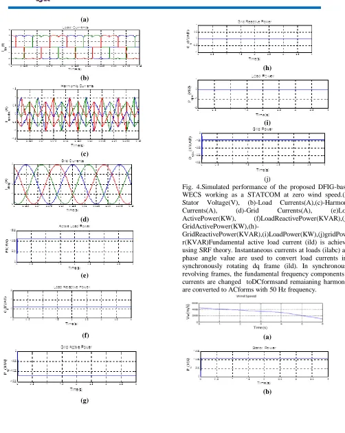
Fig. 4.Simulated performance of the proposed DFIG-based WECS working as a STATCOM at zero wind speed.(a)-Stator Voltage(V), (b)-Load Currents(A),(c)-Harmonic Currents(A), (d)-Grid Currents(A), (e)Load ActivePower(KW), (f)LoadReactivePower(KVAR),(g)-
GridActivePower(KW),(h)-GridReactivePower(KVAR),(i)LoadPower(KW),(j)gridPowe r(KVAR)Fundamental active load current (ild) is achieved using SRF theory. Instantaneous currents at loads (ilabc) and phase angle value are used to convert load currents into synchronously rotating dq frame (ild). In synchronously revolving frames, the fundamental frequency components of currents are changed toDCformsand remaianing harmonics are converted to ACforms with 50 Hz frequency.
(a)
(c)
(d)
(e)
Fig. 5.Waveforms of proposed DFIG for fall in wind speed.(a)-wind Speed(m/s), (b)-Stator Power(KW), (c)-GSC
Power(KW), (d)-Load Power(KW),(e)-Rotor Currents(A) Load current (ild) in the synchronously revolving frame and loss component of current at GSC (i∗gsc) is shown in below equation as
𝑖𝑔𝑑∗ = 𝑖
𝑔𝑠𝑐∗ + 𝑖𝑑𝑠− 𝑖𝑙𝑑 (18)
Load currents of Direct currents values in synchronously revolvingdq frame (ild) is pulledby means of low-pass filter (LPF).For generating the switching pulses the hysteresis current controller is used. The feedback controller which controls the current in hysteresis controllerheresensed current meets the reference current in a loop of hysteresis band (ihb). At every point of instant, the actual current (igabc) is compared to the reference current (i∗gabc) is as ∆𝑖𝑔𝑎𝑏𝑐= 𝑖𝑔𝑎𝑏𝑐∗ − 𝑖𝑔𝑎𝑏𝑐(19)
When ∆𝑖𝑔𝑎𝑏𝑐 > 𝑖ℎ𝑏lower switch is turned ON (20)
When ∆𝑖𝑔𝑎𝑏𝑐> 𝑖ℎ𝑏, upper switch is turned ON(21)
Using these equations, gating pulses for three phases of GSC aregenerated .
VI. RESULTS AND DISCUSSION
The results of both simulated and test are explained herefor validating steady-state and dynamic performances of this proposed DFIG with integrated active filter capabilities. (iv)
(a)
(b)
(c)
(d)
(d)
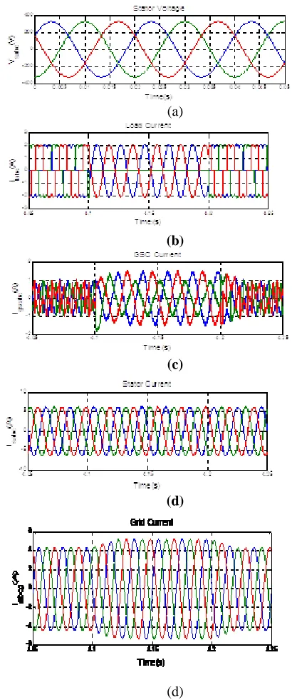
Fig. 8. DFIG-based on WECS when loads are suddenly removed and when used of local loads.(a)-StatorVoltage(V)
,(b)-Load Currents(A),(c)-GSC Currents,(d)-Stator Currents(A),(e)-grid Currents(A)Here we can observe Stator
voltage, Load current, GSC currents, Stator currents, Grid currents waveforms for sudden removal of load.
VII. CONCLUSION
bought by means ofGrid Side Converter(GSC). The Grid Side Converter (GSC)algorithm in suggested DFIG has been changed for the contributing reactive power and minimization of harmonics at local loads in proposed DFIG is done by means of Grid Side Converter. Rotor Side Converter(RSC) is mainly helped for the separate control of reactive power and active. The proposed DFIG has been tested at wind turbine stall situation for rewarding harmonics and reactive active power of local loadsThis proposed DFIG-based WECS with an combined active filter has been replicated by MATLAB\Simulink environment, and the imitation results are corroborated for different conditions of wind speed and unexpected application of removal of local loads. Steady-state performance and active performance of the DFIG system with the proposed control strategy has been verified for various conditions as mentioned above.
REFERENCES
[1] D. M. Tagare, Electric Power Generation the Changing Dimensions. Piscataway, NJ, USA: IEEE Press, 2011. [2] G. M. Joselin Herbert, S. Iniyan, and D. Amutha, “A review of technical issues on the development of wind farms,” Renew. Sustain. Energy Rev., vol. 32, pp. 619–641, 2014.
[3] I. Munteanu, A. I. Bratcu, N.-A. Cutululis, and E. Ceang, Optimal Control of Wind Energy Systems Towards a Global Approach. Berlin, Germany: Springer-Verlag, 2008.
[4] A. A. B. Mohd Zin, H. A. Mahmoud Pesaran, A. B. Khairuddin, L. Jahanshaloo, and O. Shariati, “An overview on doubly fed induction generators controls and contributions to wind based electricity generation,” Renew. Sustain. Energy Rev., vol. 27, pp. 692–708, Nov. 2013.
[5] S. S. Murthy, B. Singh, P. K. Goel, and S. K. Tiwari, “A comparative study of fixed speed and variable speed wind energy conversion systems feeding the grid,” in Proc. IEEE Conf. Power Electron. Drive Syst. (PEDS’07), Nov. 27–30, 2007, pp. 736–743.
[6] D. S. Zinger and E. Muljadi, “Annualized wind energy improvement using variable speeds,” IEEE Trans. Ind. Appl., vol. 33, no. 6, pp. 1444– 1447, Nov./Dec. 1997.
[7] H. Polinder, F. F. A. van der Pijl, G. J. de Vilder, and P. J. Tavner, “Comparison of direct-drive and geared generator concepts for wind turbines,” IEEE Trans. Energy Convers., vol. 21, no. 3, pp. 725–733, Sep. 2006.
[8] R. Datta and V. T. Ranganathan, “Variable-speed wind power generation using doubly fed wound rotor induction machine—A comparison with alternative schemes,” IEEE Trans. Energy Convers., vol. 17, no. 3, pp. 414–421, Sep. 2002.
[9] E. Muljadi, C. P. Butterfield, B. Parsons, and A Ellis, “Effect of variable speed wind turbine generator on stability of a weak grid,” IEEE Trans. Energy Convers., vol. 22, no. 1, pp. 29–36, Mar. 2007.
[10] R. Pena, J. C. Clare, and G. M. Asher, “Doubly fed induction generator using back-to-back PWM converters and its application to variable-speed wind-energy generation,” IEE Proc. Elect. Power Appl., vol. 143, no. 3, pp. 231–241, May 1996.
MANCHIKANTI PRASHANTHI
Completed B. TECH in Electrical & Electronics Engineering in 2015from ACE Engineering College affiliated to JNTUH, Hyderabad and Pursuing M.Tech from ANURAG Group of Institutions(Formerly known as CVSR College of Engineering(Autonomous) Affiliated to JNTUH, Hyderabad, Telangana, India. Area ofinterest includes Power Electronics. E-mail id:[email protected]
DR.GOPALA VENU MADHAV Venu Madhav Gopala received his B.Tech. degree in Electrical and Electronics Engineering from Jawaharlal Nehru Technological University, Hyderabad in 2002. M.Tech. degree in Power and Industrial Drives from Jawaharlal Nehru Technological University, Anantapur in 2005. He obtained his Ph.D. from Jawaharlal Nehru Technological University, Hyderabad in 2016. He also completed Master of Business Administration (MBA) from Annamalai University in 2013. Currently he is working as Professor, Dept. of EEE, Anurag Group of Institutions. He has published several National and International Journals and Conferences. His area of interest is Advanced Control strategies of Electric Drives, Renewable Energy Technologies, Microprocessors and Microcontrollers, Fuzzy logic & ANN applications, and Network Analysis. Have professional society memberships in IEEE (M), IETE (M), ISTE (LM), IE (AM), SESI (LM), NIQR (LM), SSI (LM), SPE (LM), ISCA (LM), IAENG (LM), IACSIT (LM) and C Eng.