A repository for the
management of artifacts
in system engineering
By Edwin van Wasbeek
A repository for the management of
artifacts in system engineering
Student:
Ing. E. van Wasbeek
Committee:
Dr. Ir. K.G. van den Berg University of Twente, department EEMCS-SE Dr. Mr. Ir. Th.J.G. Thiadens University of Twente, department BBT-IS&CM
M. Fillerup Chess BV, department I-business
Dr. Ir. J.P. Zwart Chess BV, department I-business
Version 1.0 Status: Final
Enschede, 28 August 2006
Internal project Chess: FOREST
University of Twente
P
REFACE
In front of you lay my last assignment to complete my study Master of Business Information Technology at the University of Twente. Completing this study is a great achievement for me especially because of my dyslexia. This dyslexia made my study at the university allot harder for me.
This final project was executed at the software development department of Chess BV situated in Haarlem. Chess wanted me to investigate a new way of storing the design information. This question resulted in this final project with the subject to examine and design a repository to store software artifacts created during the software design activity.
First of all, I want to thank my four supervisors, Klaas van den Berg and Theo Thiadens of the University of Twente, and Mats Fillerup and Joris Zwart from Chess BV for their support during this research project.
I want to thank all the other employees of Chess BV for their hospitality and joyful working environment. My thanks especially go out to my colleagues in my room, who are Pascal, Rolf, and Ampica.
I specially want to thank Hans, Trinet, Marc, and Bas van de Peet for their hospitality. They let me stay at their house in Hoofddorp during my research project. I enjoyed the time spending with this family.
Great thanks go out to my parents for supporting and believing in me throughout the collage years. They believed that I could finish the university, even when I had some hard times. Without them I did not reach this point in my life. I also want to thank my little brother for correcting my English in this thesis.
Least, but not last I want to thank all my friends, especially my two roommates and the members of the executive board 2004-2005 of T.C. Ludica for supporting me.
Enschede, 28 August 2006
M
ANAGEMENT SUMMARY
The research took place at Chess BV in Haarlem. Software design at Chess (and other companies) is done in MS Word documents in which the systems decomposition is stated. MS Word documents are very simple in use but lack analysis checking features. Chess identifies this as a problem and that is why this research was started.
The problem for this research was defined as: “How to manage software design artifacts within Chess?”. Design artifacts are parts of information about the system, like the structure or
requirements of the system. The answer to this question led to a repository that supports the management of design artifacts, numerous of analysis checks on these artifacts, and the generation of documentation. To reach this goal, an explorative research in the literature was performed to provide a theoretical base. This theory is then used for analyzing the current situation and designing a new repository where the design artifacts are stored and managed in.
Nowadays, development projects are getting bigger and more complex. This means that large amounts of design artifacts are created and these artifacts need to be stored somewhere. This also means that when changes occur (and they do) these design artifacts need to be changed. All these problems demand facilities for storing and managing the design artifacts in a repository.
Nowadays MS Word documents and UML (Unified Modeling Language) diagrams are the primary repositories for storing and managing artifacts created in the software design activity. MS Word documents are very simplistic and do not support different analysis checks. UML diagrams however are very detailed in specifying a software design, but are complex and difficult to use. To make the use of these documents and diagrams easier, different tooling, like text editors and UML design tooling, is provided.
The repository suggested in this thesis tries to take the strengths of both storage facilities. The repository supports different analysis checks, but will be simple in use. It is also very flexible in how the design process is executed and does not have many constraints on how to use the repository. The XML (Extensible Markup Language) is used to represent the different design artifacts in the repository. XML is very flexible, human editable, and supports different database functions.
Important to understand is that this first version of the repository as it is presented has only the basic functionalities to represent the design process. Future development should add new features to the repository to make it a more advanced repository.
The repository is going to have a central role in the design process. It will be the medium where all stakeholders retrieve their information from. In general there are seven stakeholders each using the information stored in the repository in their own way. The requirements engineer, designer, programmer, and the maintenance programmer are the stakeholders that add, delete, or change information in the repository. The other three stakeholders are only retrieving information from the repository. The repository also support the generation of documentation. This means that tooling developed for the repository should be able to generate documents for each stakeholder.
requirements to these sub-systems. During each decomposition step the design process is stored by means of design motivations. These state why some particular design decisions is taken by the designer. This information can be very useful when other designers try to understand the design.
The user requirements are defined in the system, which is then decomposed into sub-systems. During this decomposition the user requirements are related to the appropriated sub-system. This sub-system is then responsible to do something with this requirement and eventually should implement this requirement. This implementation can be done by the sub-system itself, or by one of its sub-systems. During the decomposition of a system new design requirements may be created which need to be fulfilled by the system, like the system should fulfill the user requirements.
By defining the different relationships in the repository traceability is made possible.
Traceability tries to follow the life of an artifact in the repository. This provides the mechanisms to execute different analysis checks and the generation of documentation. The analysis checks can be used to validate the designs or to illustrate what the impact is of a change. The generation of documentation can provide each stakeholder with its own document need to perform his task.
C
ONTENTS AT A GLANCE
1. Introduction ...1
2. Research approach...9
3. System engineering ... 15
4. System engineering in practice ... 27
5. Design Artifact management... 37
6. Traceability ... 43
7. Defining requirements ... 51
8. Testing... 55
9. Requirements for the repository ... 63
10. Designing the repository ... 71
11. The implementation of the repository... 83
12. Testing the repository... 103
13. Operating the repository ... 111
14. Existing design storage comparisons... 125
15. Conclusion and recommendations... 129
Glossary ... 135
References... 137
Appendix A. XML Repository structure tree ... 141
Appendix B. DTD of the repository ... 143
T
ABLE OF CONTENTS
1. Introduction ...1
1.1. Description of Chess ... 1
1.1.1. Structure... 1
1.1.2. Executive board... 2
1.1.3. Service departments ... 2
1.1.4. Business-lines ... 3
1.1.5. Employees... 3
1.1.6. Products and services... 4
1.1.7. Market ... 4
1.1.8. Style... 5
1.2. Reason for this research... 5
1.3. Summary... 7
2. Research approach...9
2.1. Problem statement ... 9
2.2. Goal statement ... 9
2.3. The scope of this thesis... 9
2.4. Research model ... 10
2.5. Research questions... 11
2.6. Limitations of this thesis... 11
2.7. Overview of this thesis ... 12
2.8. Summary... 13
3. System engineering ... 15
3.1. System definition ... 15
3.2. The system engineering process ... 15
3.2.1. System requirements definition ... 16
3.2.2. System design ... 16
3.2.3. Sub-system development ... 17
3.2.4. System integration ... 17
3.2.5. System installation ... 18
3.2.6. System evolution... 18
3.2.7. System decommissioning... 18
3.3. The software engineering process ... 18
3.3.1. Requirements engineering ... 19
3.3.2. Design ... 20
3.3.3. Design documentation... 22
3.3.4. Implementation... 24
3.3.5. Testing... 24
3.3.6. Maintenance ... 25
4. System engineering in practice ... 27
4.1. General development approach ... 27
4.2. The system engineering process ... 28
4.2.1. System requirements definition ... 28
4.2.2. System design ... 28
4.2.3. Sub-system development ... 29
4.2.4. System integration ... 29
4.2.5. System installation ... 29
4.2.6. System evolution... 29
4.2.7. System decommissioning... 30
4.3. The software engineering process ... 30
4.3.1. Requirements engineering ... 30
4.3.2. Design ... 31
4.3.3. Design documentation... 33
4.3.4. Implementation... 33
4.3.5. Testing... 34
4.3.6. Maintenance ... 34
4.4. Summary... 35
5. Design Artifact management... 37
5.1. Design artifacts... 37
5.2. Management of requirements and design... 37
5.2.1. Requirements management... 37
5.2.2. Design management ... 38
5.2.3. Repository ... 39
5.3. Changes ... 39
5.3.1. Requirements changes ... 40
5.3.2. Design Changes ... 40
5.4. Summary... 41
6. Traceability ... 43
6.1. Traceability definition... 43
6.2. Importance of traceability... 43
6.3. Stakeholders for traceability ... 44
6.4. Traceability directions ... 44
6.5. Relationships between requirements and design ... 46
6.6. Traceability analysis ... 48
6.7. Summary... 48
7. Defining requirements ... 51
7.1. Definition ... 51
7.2. Types of requirements ... 51
7.2.1. Business requirements ... 51
7.2.2. Functional requirements ... 52
7.2.3. Non-functional requirements ... 52
7.4. Summary... 53
8. Testing... 55
8.1. The test process... 55
8.1.1. Lifecycle... 56
8.1.2. Techniques ... 57
8.1.3. Infrastructure ... 58
8.1.4. Organization ... 58
8.2. Requirements-based testing... 58
8.3. Testing functional requirements... 59
8.4. Testing non-functional requirements ... 60
8.5. Summary... 61
9. Requirements for the repository ... 63
9.1. First version ... 63
9.2. Artifacts in the repository ... 63
9.3. Stakeholders ... 64
9.4. User requirements... 64
9.4.1. Business requirements ... 65
9.4.2. Functional requirements ... 65
9.4.3. Non-functional requirements ... 66
9.4.4. Requirements matrices... 68
9.5. Exclusions ... 69
9.6. Summary... 70
10. Designing the repository ... 71
10.1. Repository approach ... 71
10.1.1. Example justification ... 72
10.1.2. Example ... 72
10.1.3. Reflection ... 72
10.2. Using the repository approach... 73
10.3. Relationships ... 74
10.3.1. Dependency term and relationships ... 75
10.3.2. Requirement refinement ... 75
10.3.3. System refinement... 75
10.3.4. Requirement assigning... 76
10.3.5. Requirement implementation ... 76
10.3.6. Relationship explanation ... 76
10.4. Traceability in the repository... 77
10.4.1. Types of traceability ... 77
10.4.2. Directions of traceability ... 78
10.4.3. Example of a trace in the repository... 78
10.5. Types of analysis... 79
10.5.1. Analysis and tooling ... 79
11. The implementation of the repository... 83
11.1. Extensible Markup Language... 83
11.2. Structure of the elements ... 83
11.2.1. System element... 85
11.2.2. Subsystem element... 87
11.2.3. Requirement element ... 88
11.2.4. Declaration element ... 89
11.2.5. Implements element ... 90
11.2.6. Implementation element ... 91
11.2.7. Mapping element ... 92
11.2.8. Source element ... 93
11.2.9. Target element ... 94
11.2.10. Motivation element... 95
11.2.11. Description element ... 95
11.2.12. Title element ... 95
11.3. Implementation and mapping usage ... 95
11.4. Unique identifiers ... 97
11.5. File based or database repository ... 99
11.6. Document generation... 99
11.6.1. Solution to the document problem ... 99
11.6.2. Information...100
11.6.3. Document users and types ...100
11.7. Summary...101
12. Testing the repository... 103
12.1. Tooling ...103
12.2. Functional requirements ...103
12.3. Non-functional requirements ...107
12.4. Proof of concept ...109
12.5. Summary...110
13. Operating the repository ... 111
13.1. Repository use ...111
13.1.1. Defining the system “SY_Fiscal_Tax” ...112
13.1.2. Defining the sub-systems “SS_Software”...116
13.1.3. Defining the sub-systems “SS_Documentation” ...118
13.2. Rules for the use of the repository ...119
13.3. Stakeholders ...120
13.3.1. Requirements engineer ...121
13.3.2. Designer...121
13.3.3. Project manager ...122
13.3.4. Configuration manager ...122
13.3.5. Programmer...122
13.3.6. Unit tester and integration tester...123
13.4. Summary...123
14. Existing design storage comparisons... 125
14.1. Unified Modeling Language diagrams...125
14.2. MS Word documents ...126
14.3. Comparison ...127
14.4. Summary...128
15. Conclusion and recommendations... 129
15.1. Conclusion ...129
15.2. Evaluating research questions ...130
15.3. Recommendations and future work ...131
15.4. Reflection...132
Glossary ... 135
References... 137
Appendix A. XML Repository structure tree ... 141
Appendix B. DTD of the repository ... 143
L
IST OF FIGURES
Figure 1.1 - Organization structure Chess... 2
Figure 1.2 - Some disciplines involved in system engineering based on [58] ... 5
Figure 1.3 - Different documents and different users... 6
Figure 2.1 - Research model... 10
Figure 3.1 - Some disciplines involved in system engineering based on [58] ... 15
Figure 3.2 - The system engineering process [58] ... 16
Figure 3.3 - The system design process [58]... 17
Figure 3.4 - The software engineering process based on [1][58][67] ... 19
Figure 3.5 - The requirements engineering activity [58] ... 19
Figure 3.6 - The software design activity [58] ... 21
Figure 3.7 - The testing activity [58] ... 25
Figure 4.1 - JSTD 016 system development process based on [63] ... 27
Figure 4.2 - Chess software design process... 31
Figure 4.3 - System decomposition... 33
Figure 6.1 - Directions of traceability relations ... 45
Figure 6.2 - Relationships in requirements and design ... 46
Figure 7.1 - The ISO 9126 quality attributes based on [49] ... 52
Figure 8.1 - The four pillars for structured testing [49] ... 55
Figure 8.2 - Hierarchy of the test sorts [49]... 56
Figure 8.3 - TMap phases based on [49][65]... 57
Figure 8.4 - Test-case form ... 60
Figure 9.1 - Repository stakeholders... 64
Figure 10.1 - House build process ... 71
Figure 10.2 – Black-box of the design process... 73
Figure 10.3 – The house build process and the artifacts... 74
Figure 10.4 - Repository use and placement ... 74
Figure 10.5 - Mapping and implementation description ... 77
Figure 10.6 - An example trace of “Req 1” ... 78
Figure 11.1 - A simplified element tree of the repository... 84
Figure 11.2 - Class diagram of the repository... 85
Figure 11.3 - A basic System element ... 86
Figure 11.4 - A basic Subsystem element ... 87
Figure 11.5 - A basic Requirement element... 88
Figure 11.6 - A basic Declaration element... 89
Figure 11.7 - A basic Implements element... 91
Figure 11.8 - A basic Implementation element ... 92
Figure 11.9 - A basic Mapping element... 93
Figure 11.10 - A basic Source element ... 94
Figure 11.11 - A basic Target element ... 94
Figure 11.13 - A basic Description element ... 95
Figure 11.14 - A basic Title element ... 95
Figure 11.15 - A basic Target element ... 96
Figure 11.16 - Parent Requirement mapping with sub-requirements ... 96
Figure 11.17 - Parent requirement mapping... 96
Figure 11.18 - Multiple sub-requirement mapping... 97
Figure 11.19 - Example of the use of word identifiers ... 98
Figure 12.1 - Test-case for requirements [F1] and [F3] ...104
Figure 12.2 - Test-case for requirements [F4] ...105
Figure 12.3 - Test-case for requirements [F5] ...105
Figure 12.4 - Test-case for requirement [F2] ...106
Figure 12.5 - Test-case for requirements [F6] ...107
Figure 13.1 - Repository use steps ...111
Figure 13.2 - Defining the system ...113
Figure 13.3 - Defining user requirements for the system...113
Figure 13.4 – Defining design requirements for the system ...113
Figure 13.5 - Defining a sub-systems for the system...114
Figure 13.6 – Implementing the requirements on the new sub-systems ...115
Figure 13.7 - Mapping the requirements on the new sub-systems ...115
Figure 13.8 - Sub-systems design ...116
Figure 13.9 - Defining design requirements for the sub-system ...116
Figure 13.10 - Declaring a sub-system in the sub-system ...117
Figure 13.11 – Mapping requirements on the new sub-systems ...118
Figure 13.12 - Defining design requirements for the sub-system...118
Figure 13.13 - Defining declarations for the sub-system ...119
Figure 13.14 - Repository users ...120
Figure 13.15 - Repository use steps with the users ...121
L
IST OF TABLES
Table 3.1 - User roles and attributes [4]... 23
Table 3.2 - Views on the design documentation [4]... 23
Table 5.1 - Requirements change causes based on [68] ... 40
Table 9.1 – Business, functional, and non-functional requirements matrix ... 68
Table 9.2 - Technical requirements and stakeholders matrix... 69
Table 11.1 - Attributes of the System element ... 86
Table 11.2 - Elements of the System element ... 86
Table 11.3 - Attributes of the Subsystem element ... 87
Table 11.4 - Elements of the Subsystem element ... 88
Table 11.5 - Attributes of the Requirements element... 89
Table 11.6 - Elements of the Requirements element ... 89
Table 11.7 - Attributes of the Declaration element ... 90
Table 11.8 - Elements of the Declaration element ... 90
Table 11.9 - Attributes of the Implements element ... 91
Table 11.10 - Elements of the Implements element ... 91
Table 11.11 - Attributes of the Implementation element ... 92
Table 11.12 - Elements of the Implementation element ... 92
Table 11.13 - Attributes of the Mapping element ... 93
Table 11.14 - Elements of the Mapping element ... 93
Table 11.15 - Attributes of the source element... 94
Table 11.16 - Attributes of the Target element ... 94
Table 11.17 - User roles and attributes [4] ...101
Table 12.1 - Non-functional requirements checklist ...108
Table 12.2 - Quality attributes checklist ...109
L
IST OF ABBREVIATIONS
DTD Document Type Definition HRM Human Resources Management IDE Integrated Development Environments
M2M Machine-to-Machine
OEM Original Equipment Manufacturer OMG Object Management Group
PR Public Relations
RBT Requirements Based Testing
SME Small and Medium Sized Enterprises UML Unified Modeling Language
1.
I
NTRODUCTION
In this first introductionary chapter, a description of Chess BV is given to get a better
impression and understanding of the company where this research project took place. For the ease of reading, Chess BV will be directed as Chess in this thesis.
The section 1.1 describes the different organizational parts of Chess. This part does not include the way system engineering is performed at Chess. This will be described in chapter 4. In section 1.2 the motivation for the execution of this research project will be elaborated. Finally, in the last section a summary of this chapter is given.
1.1.
Description of Chess
Chess is a company specialized in problem solutions and services in high-end electronic products, M2M applications and critical internet applications. This is all realized from the two locations Haarlem and Best in the Netherlands. From these two locations, Chess clientele consists of many of the top 100 Dutch companies [10]. Some examples of Chess its customers are:
Interpay; ING-Bank; Rabobank; ABN-AMRO; Shell; Philips; Siemens; Akzo Nobel; Unilever; Ahold.
In the following sub-sections, information about the company structure, the employees, the products and services, the targeted market and the style of Chess is provided. This information is retrieved from the Chess website [10], by informal interviews or conversations, and the summary of the policy plan 2006 [26]. This last source is classified and can not be made public for external use.
1.1.1.
Structure
Figure 1.1 - Organization structure Chess
1.1.2.
Executive board
The executive board controls the business-lines and the services departments by means of direct targeting and coordination. This is done by organizing management team consultations where representatives of all business-lines, service departments and the executive board, are present. In these consultations the current and the desired situation like planning and the financial status of projects are discussed.
The following enumeration summarizes some of the responsibilities of the executive board:
Maintaining the relationships with the shareholders; Organizational and business development;
Portfolio management; Treasury and financing;
Maintaining internal and external communication.
1.1.3.
Service departments
The service departments support and partially execute the company policy directed by the executive board. They also form the link between the executive board and the business-lines and support the business-lines in their execution of their tasks.
The following enumeration summarizes some of the responsibilities of the service departments:
Accounting: supports information provision, finance, administration and justification; PR and communication: maintains the Chess style, image, reputation, website and public
relations tools;
Human Resource Management (HRM): deals with laws, administration, recruitment and the selection of employees;
Purchasing: does planning, purchasing, control, and the communication with the business-lines;
Unit production: is involved in the production and testing of the products designed by the business-lines;
Innovation team: is responsible for the creation of new products or services and is in close contact with the business-lines.
1.1.4.
Business-lines
The business-lines are responsible for the operation of the primary processes of Chess (that means, the business lines are the primary processes of Chess). These business-lines are market oriented, are supported by the service staff and operate on a ‘profit & loss’ principle. The business-lines operate as profit centers and are entirely responsible for and focused on their own profit [17]. They develop products, execute projects, and are responsible for customer relations.
The main activities of the business-lines are:
Sales; Delivery;
Product and service development; Business-line communication; Operational HRM;
Operational PR; Planning and control.
As illustrated in Figure 1.1 there are four business-lines to meet market demand. These business-lines are:
I-Business: aims at multi-channel software solutions and company critical systems; M2M Secure Solutions: The engineering process of M2M Secure Solutions characterizes
itself by multidisciplinary development of casings, hardware, system software, embedded- and server application software;
High Performance Solutions: aims at the development of innovative and complex embedded systems;
Sense & Control: is responsible for the management and execution of different projects. Sense & Control also produces and manages the life-cycle of different systems and products.
1.1.5.
Employees
The employees of Chess have a high technical and educational level but differ in their
To keep all employees of a business-line up to date with the current and future projects, Chess organizes informal meetings. These meetings are called ‘Chess talks’. During these talks, every project is introduced and then discussed. These ‘Chess talks’ are great way of knowledge and information sharing among colleagues.
At the moment Chess consists of about 140 employees and the prediction is that at the end of 2006 this will grow to about 170 employees. The binding factor between the Chess employees is the profession of system engineering and joy of participating in a group of inspiring colleagues and challenging projects.
1.1.6.
Products and services
Chess has different ways of delivering their products and services. Chess delivers electronic products directly ‘off the shelf’ or to the customer’s specification. This is done in project form or as part of an existing solution. Moreover, Chess provides sophisticated software solutions as projects, as turn-key solutions or as part of M2M solutions. Chess also delivers production logistics, hosting, operations, and maintenance and support services for operational systems. Applications which are developed by Chess are:
PinLinq (wireless PIN payment systems); Parking systems;
Digital Rights Management (DRM);
MiniTix (ChipKnip application for the internet); Shareholder Voting System (SVS);
E-Travel (online vacation portal).
1.1.7.
Market
Chess primarily aims on Dutch companies, generally with international markets. As described in the introduction of this chapter Chess supports some major international companies like ING, Rabobank, Siemens, and Philips (see the introduction of this section for more companies).
Besides the direct approach by the executive board and the account managers of the business-lines to attract new customers, much is expected of Chess its partners like ASML (www.asml.nl) and VDO Dayton (www.vdodayton.com), which have their own markers. Chess wants to be dominantly present in the following markets:
The financial market;
The entertainment or new media market; OEM product suppliers;
Retail markets;
1.1.8.
Style
Chess maintains a ‘high-tech’ image based on innovation and the use of the latest technologies. This gives Chess the edge to be the company for constituents and talented employees. Chess uses a ‘can do’ mentality when serving their customers. This is reached by a flexible organization and effectively arranging the processes within Chess.
How Chess is perceived by the labor market is very important for the company. Chess should be seen as a special and strong company where, besides healthy financial results, employees have a central position. In other words, Chess should be an enjoyment to work for.
The style Chess want to reflect to its customers and to its employees are described with phrases like:
Vision; High-tech; Innovative; Result-oriented;
Carefully and responsible; Communicative;
Surprising (“obtaining an eleven instead of a ten”).
1.2.
Reason for this research
System engineering includes different engineering branches that are needed for building a system [58]. These branches are software engineering, hardware engineering, electrical, and other engineering specialties. This is illustrated in Figure 1.2. Each engineering field is responsible for different parts of the system which are called sub-systems. During the system engineering process, these sub-systems are then (again) decomposed into sub-systems and so on.
Figure 1.2 - Some disciplines involved in system engineering based on [58]
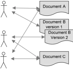
different engineering fields it is important to have up-to-date and correct documentation for all engineering fields. Otherwise the different sub-systems of the system may contain errors, may be unstable, or may not be compatible.
Figure 1.3 - Different documents and different users
Chess understands the importance of maintaining the system engineering artifacts. Although, there are at the moment no major problems in managing these artifacts at Chess, improving this activity should be considered. Improving the management of these artifacts may result in:
Cost reductions; Efficiency;
Reduction of the time to market; Better quality of the software; Better documentation.
Most solutions dealing with change management are based on the software engineering process [38]. This is just a small part of the field of the system engineering. There are at the moment several tools [39], like IBMs Rational Suit [30] and Goda Software’s AnalystPro [42] in the market which claim to help developers to manage the software artifacts.
Traditional change management methods attempt to formalize all activities concerning changes in projects [38]. Each activity must be requested, numbered, accepted, implemented and tested to prove it reached its goals. All those activities may be facilitated by specialized document flow tools, yet they still require a human to process the information in each phase. Formal methods are therefore expensive and tedious for their users.
These are some of the reasons why chess does not use these kinds of tools. The most important reason not to use these tools is that most of these tools do not fit Chess its needs. Chess does not primarily use UML [20] for designing the system which is used in most tooling. Instead Chess uses a natural language or text people use in daily life, supported by images. These images however can be UML oriented.
The problem, or disadvantage, of keeping the information in these types of documents, is the way the information is stored and can be accessed. All artifacts are stored as textual items with no possibility to relate them to each other explicitly by doing this in text. There is no possibility to automatically check all relations and thus errors can not be found by automatic analysis. This makes maintaining these documents very hard. When changes are introduced, managing these documents becomes especially hard. It is difficult to track these changes and their impact on other decisions.
The description above is primarily focused on the situation at Chess, but this does not mean that Chess is the only one with this particular problem. It is the experience of Chess and also its customers and partners that software is build in the way described above. Most of these customers and partners do not use the different tools, but relay on MS word documents.
1.3.
Summary
This chapter provided information about Chess and described the problem that was the reason for this research project. Chess is a diverse company which produces software and hardware products and provides services. Chess is situated in Haarlem and Best in the Netherlands and has some big companies as clients. Some of these companies are:
Interpay; ING-Bank; Rabobank; Unilever; Ahold.
The organization structure of is traditional with on top the executive board supported by the service departments. The primary process is done by the business lines, which are:
I-Business;
M2M Secure Solution; High Performance Solution; Sense & Control.
Chess maintains a ‘high-tech’ image based on innovation and the use of the latest technologies. It tries to serve the client in every way possible by adapting to the clients whishes. This is reached by effectively arranging the processes and having highly skilled employees.
happen that different versions of documents are used by the different stakeholders. Eventually, the system may contain errors and may not satisfy the requirements of the customer. The conclusion is that the system engineering artifacts need to be managed
Chess understands the importance of maintaining the system engineering artifacts. Improving the management of these artifacts may result in:
Cost reductions; Efficiency;
2.
R
ESEARCH APPROACH
In the previous chapter the motivation was given for this research project. In this chapter the structure of this research project is given. The book of Verschuren and Doorewaard [66] is used to define this structure.
The sections 2.1 and 2.2 present the problem and the goal statements for this research project. These statements formulate the reason why this research project is taken place. In section 2.3. the reduction of the scope of this research thesis is explained. To answer the problem statement and achieve this projects goal, a research model is drawn in section 2.4 to visualize and structure the research approach. The research questions which are used to reach the projects goal are derived form the research model. These research questions are described in the section 2.5 and will be used to collect the necessary information needed for this research project. In section 2.6 some principles and limitations are given to narrow the research. In the final section the overview of this is presented.
2.1.
Problem statement
The problem statement for this research project is:
How to manage system engineering artifacts within Chess?
2.2.
Goal statement
As the result of the problem statement, the goal for this research is:
Develop a repository for the management of artifacts in system engineering.
The key terms in this goal statement are repository, management, artifacts, system engineering and will be discussed in detail in this thesis.
2.3.
The scope of this thesis
The goal stated in the previous section is very general and large-scaled. It states a general goal for multiple and different research projects or thesis. That is why this thesis will only focus on a small part of this research goal. The scope of this research thesis needs to be narrowed down to have a positive, usable and reachable result. Trying to do the whole goal in one project will be very hard mainly duo the following two reasons:
Time constraint: The time for this research project is about six months which is not very long. Because of the size of the research project, it would be impossible to perform this research in the available time.
Because of these two reasons, the research projects scope will be reduced to only the software design activity of the software engineering process. This means that the research itself focuses on the management of software design artifacts. Defining what the software design artifacts are is a part of this thesis. The reduction of the scope automatically reduces the problem and goal area.
The problem statement of this thesis is:
How to manage software design artifacts within Chess?
The goal of this thesis is:
Develop a repository for the management of artifacts in software design.
The goal of the research project, which is stated in the previous section, will be incrementally reached in different research projects. This means that like this thesis, other sub-projects will be created to add piece by piece a solution to reach the research projects goal. The success of the research project depends on the success and results of this thesis. When the outcome,
conclusions, and recommendations of this thesis are negative or unsuccessful, the assessment of the whole research will be negative and thus not applicable for further investigation.
2.4.
Research model
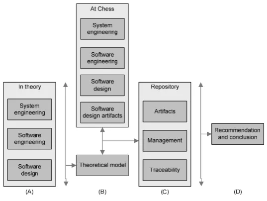
A research model indicates how a research project is shaped and how the end result is delivered. Figure 2.1 demonstrates this research model for this research project and should be read from left to right. The model is developed with the diminishment of the scope of the research project in mind.
Translating this model in to words looks like: (A) As a result of a theoretical exploration of the system engineering process, the software engineering process, and the software design process, (B) a theoretical model is formed which is used to analyze the current situation of Chess. (C) These results are then used as a foundation for the description and design of the repository. This includes a study on management, traceability and repositories and how this can be used for the software design repository. (D) Finally a recommendation and conclusion is given regarding the proposed repository.
2.5.
Research questions
The following research questions are obtained from the research model in Figure 2.1. These research questions will be used to gather more information about the key terms mentioned in the goal statement. The questions are formulated with the diminishment of the scope in mind.
[R1] What is system engineering in theory and in practice? [R2] What is software development in theory and in practice? [R3] What is software design in theory and in practice?
[R4] What are the artifacts of software design in theory and in practice? [R5] Why is management of software design necessary?
[R6] What is traceability?
[R7] How can traceability be used in management of software design?
[R8] What trace information is needed for the management of software design? [R9] What is a repository?
[R10] What are the requirements for such a repository? [R11] Which information needs to be stored in a repository?
[R12] How can trace information of software design be saved in a repository? [R13] What is the design of the repository?
[R14] How to implement and test this repository?
[R15] How can trace information of software design saved in a repository be used for document generation?
2.6.
Limitations of this thesis
Because of the constraints mentioned in section 2.3, the research project contains the following limitations:
The focus for this research is, as described in section 2.3, only on software design activity of the software engineering process, and thus leaves all other activities of system and software engineering out of consideration. This is mainly done duo to the time constraint and interest field of Chess. The outcome of this research can be used as a basis for a repository to manage the artifacts in system engineering;
Only the basic and necessary functionalities are implemented in the first version of the repository. This means that the requirements, design decisions and the relations between these items need to be stored in the repository. The requirements of this first version are described in section 9.
2.7.
Overview of this thesis
In this section the overview or structure of this thesis is given. This thesis is based on the research questions stated in section 2.5. Each chapter answers one or more of these questions.
Chapter 1: gives the introduction about chess. It described among other things the structure, markets, employees of Chess. It also provided the reason for this research project;
Chapter 2: describes the structure and the approach of this research project. This section is part of this chapter;
Chapter 3: describes the system and software engineering as it is stated in the literature. The section about software design gets special attention because this is the scope of this thesis;
Chapter 4: uses the information gathered in the previous section to examine the system engineering process at Chess. The section structure is kept the same as that of chapter 3 to describe each part of the system engineering process;
Chapter 5: describes what artifact management is and why it is needed. It provides what artifacts need to be managed and what the causes are for these artifacts to change; Chapter 6: explains the concept of traceability. It describes the importance, the
stakeholders, the directions, the relations, and the analysis types of traceability. This chapter will later be used to define the different relations in the repository;
Chapter 7: states the different stakeholders, requirements and quality attributes of the repository. The requirements and quality attributes will be used for testing and accepting the repository design;
Chapter 8: provides the design of the repository. It describes the design approach which is used by chess. The information of this chapter will be used as the foundation in the
repository. Also, the different traceability relations and analysis checks mentioned in chapter 6 that are used by the repository are described;
Chapter 9: describes the implementation of the repository. It starts of with the motivation why XML is used as language for the repository. Then the structure with the different elements and attributes is provided;
Chapter 10: defines the repository test-cases. The chapter begins with a description of the test process and how testing should be done. After this, the functional requirements and quality attributes are checked against the repository;
Chapter 11: describes the operation of the repository. It provides a detailed description of how a designer could use the repository during his design activity;
Chapter 13: states the conclusion, evaluation of the research questions, recommendations and future work, and a reflection of this thesis;
Appendixes: provide background information used by the different chapters.
2.8.
Summary
This chapter provided information about the information about the goal and approach of this research project. The goal of this research project is:
Develop a repository for the management of artifacts in system engineering.
The goal of this thesis differs from the goal of the research project because of the time limitations and the width of the scope of this goal. The goal for this thesis is:
Develop a repository for the management of artifacts in software design.
To reach this goal a research model was provided. This research model starts with collecting information from the literature about system engineering, software engineering, and design activity. This literature study is used to analyze the situation at Chess. After this analysis information about artifacts, management, and traceability is gather which is used to design the repository.
From this model some research questions arise, which are used to research this thesis its goal. Also, some limitations of this research are provided. These limitations are:
The limitation that this thesis is only focusing on the software design activity;
Only a design of the repository will be provided (That means no tooling shall be written for the repository);
3.
S
YSTEM ENGINEERING
This chapter describes the system engineering and the software engineering process. These descriptions are based on the book of Sommerville [58], and are sometimes supported by other references. The information provided in this chapter will be regarded as correct and will be used in chapter 4. to analyze the way Chess performs its system engineering process. Section 3.1
describes the definition of the term system. Second 3.2 describes system engineering process and section 3.3 describes the software engineering process. The last section will give a summary of the information given in this chapter.
3.1.
System definition
Before describing what system engineering exactly is, it is important to know what a system is. The definition of a system is a collection of components organized to accomplish a specific function of set of functions [31]. To be more specific, a system is any organized assembly of personnel, resources and procedures united and regulated by interaction or interdependence to accomplish a set of specific functions [32]. The first definition is only mentioning components, where the second definition is concerned with persons, resources and procedures. This is much wider then only hardware or software components.
3.2.
The system engineering process
System engineering is the activity of specifying, designing, implementing, validating, deploying, and maintaining systems as described in de design definition. System engineers are not just concerned with software, but also with hardware and the system’s interactions with its users and its environment. System engineers must think about the services that the system provides the constraints under which the system must be build and operate, and the ways in which the system is used to fulfill its purpose.
Figure 3.1 - Some disciplines involved in system engineering based on [58]
The system engineering process exists of seven activities which are illustrated in Figure 3.2. This model was an important influence on the model of the software engineering process that is described in section 3.3. Take note that the system engineering, like all other engineering processes are interactive and can contain loop-backs to a previous activity.
Figure 3.2 - The system engineering process [58]
In the following sub-sections, the seven activities of the system engineering process are described. Each sub-section relates to an activity from Figure 3.2.
3.2.1.
System requirements definition
The system requirements definition specifies what the system should do (its functions), its essentials, and desirable system properties. An important part of the requirements definition phase is to establish a set of overall objectives that the system should meet. These should not necessary be expressed in terms of the system its functionality, but should define why the system is being produced for a particular environment.
Creating system requirements definitions involves consultations with the system its customers and end-users. The requirements definition phase usually concentrates on delivering three types of requirements:
Functional requirements: are the basic function the system must provide at an abstract level;
Non-functional requirements: or quality attributes are the non-functional system properties of the system by which its quality will be judged by some stakeholder or stakeholders; Characteristics that the system must not exhibit: specify what the system must not do.
3.2.2.
System design
In the system design process, systems may be modeled as a set of sub-systems and
components with relationships between these sub-systems and components. These are normally illustrated graphically in a system architecture model that gives the reader an overview of the system its organization.
components. The functional components, when viewed from the sub-system’s perspective, provide a single function.
System design is concerned with how the system functionally is to be provided by the components of the system. The activities of this process, as illustrated in Figure 3.3, are:
Partition requirement: is the activity of analyzing the requirements and organize them into related groups;
Identify sub-system: is the activity of finding sub-systems that can individually or collectively meet the system requirements;
Assign requirements to sub-systems: is the activity of allocating the requirements to sub-systems;
Specify sub-system functionality: is the activity of defining functionalities provided by each sub-system;
Define sub-system interface: is the activity of specifying the interfaces that are provided and required by each sub-system.
Figure 3.3 - The system design process [58]
The double-ended arrows in Figure 3.3 imply that there is a lot of feedback and iteration from one activity to another. When problems and new ideas arise, the previous activity or activities need to be redone.
3.2.3.
Sub-system development
During the sub-system development, the sub-system identified in the system design activity, is build and implemented. This may involve starting another system engineering process for
individual sub-systems or, if the sub-system is software, starting a new software engineering process. In this new process, all sub-systems and components are build according to the specifications of the design.
3.2.4.
System integration
During the system integration process, the independently developed sub-systems and
Once the sub-systems and components are integrated in the entire system, extensive system testing is take place. The attentions of these tests are on testing the interfaces between the sub-systems and components and the behavior of the entire system. An acceptance test is executed by the customer to accept the system for use.
3.2.5.
System installation
After the system is fully tested en found ready for use, the system needs to be installed at the customer. During the installation, all different engineering fields are brought together to install the system and finalize the system development process. This finalizing of the system development process means that each engineering filed helps and supports the customer in the use of the system. After this installation activity, the customer is ready to use the system in its organization.
3.2.6.
System evolution
The system evolution process is responsible for keeping the system up-to date and bug free. During the life of systems which ends at the decommissioning of the system, changes and errors may occur. This means that requirements need to be changed or created, designs need to be redesigned and that the system needs to be rebuild. Possible reasons for a system change are:
The hardware may change;
The use of the system may change;
The environment of the system may change;
The software may be obsolete and need to be changed.
3.2.7.
System decommissioning
System decommissioning is the activity of taking the system out of service after the end of its useful operational lifetime. This could for hardware systems be disassembling and recycling materials. Still valuable components like software or hardware can be reused for another system
3.3.
The software engineering process
The software development process is an organized set of activities performed to translate user needs into software products [54]. It is the process of the initial birth of software to its death (Software life cycle).
One of the first introductions of software engineering models was the waterfall model. It captures the ideal process of software engineering in one model and is a result of the system engineering model shown in Figure 3.2. Both models have almost the same activities and the same order of these activities.
The waterfall model derives its name due to the cascading effect from one activity to the other as show in Figure 3.4. In this model each activity has a well defined starting and ending point, with identifiable deliveries to the next activity [1][58][67].
activity of the software engineering process, but focuses more on the documentation of the design activity.
Figure 3.4 - The software engineering process based on [1][58][67]
3.3.1.
Requirements engineering
Requirements engineering or software specification is the activity of understanding and defining what services are required from the system (that means, the requirements) and identifying the constraints on the system its operation and development. At the end of this activity a
requirements document is created, which identifies the specification of the system.
Figure 3.5 - The requirements engineering activity [58]
The requirements engineering activity is illustrated in Figure 3.5. The model suggests that the sub-activities in the requirements engineering activity are simply carried out in a strict sequence, but this is not the case. Throughout this activity, and even beyond this activity, existing
requirements may change and new requirements may be introduced, which need to be specified and validated. Therefore the sub-activities of analysis, specification and validation are interleaved. The sub-activities of the requirements engineering are:
the proposed system will be cost-effective from a business point of view and whether it can be developed within existing budgetary constraints. The result should decide whether to go ahead with a more detailed analysis;
Requirements elicitation and analysis: is the process of deriving the system requirements through observation of existing systems, discussion with potential users and procurers, task analysis and much more. This may lead to the development of one or more system models and prototypes. These help the analyst understand the system to be specified;
Requirements specification: is the activity of translating the information gathered during the analysis activity into a document that defines a set of requirements. Two types of requirements may be included in this document. User requirements are abstract statement of the system requirements for the customer and end-users of the system. System
requirements are a more detailed description of the functionality to be provided by the system;
Requirements validation: checks the requirements for realism, consistency and
completeness. During this process, errors in the requirements documents are inevitably discovered. The requirements document must then be modified to correct these problems.
3.3.2.
Design
A software design is a description of the structure of the software to be implemented, the data which is part of the system, the interfaces between system components and, sometimes, the algorithms used. The design activity is the activity of designing the architecture, components, interfaces, and other characteristics of a system or component [31]. This design activity, shown in Figure 3.6, involves adding formality and detail as the design is developed with constant
backtracking to correct earlier designs. The design process may involve developing several models of the system at different levels of abstractions.
The input of the design phase is the requirements document created in the requirements engineering phase, describing ‘what’ the system should do. The outputs of the design activity are design documents, describing ‘how’ the system is to achieve the requirements [67].
Figure 3.6 may suggest that the activities of the design process are sequential, but in fact like all activities of system engineering, the activities are interleaved. The model described in this thesis, is a general model of the design process and may in practice differ. Some of these design activities are executed in the implementation activity or not even at all. The sub-activities of the design activity, shown in Figure 3.6, are:
Architecture design: the systems is decomposed into sub-systems and the relationships between these sub-systems are identified and documented;
Abstract specification: for each sub-system an abstract specification of its services and the constraints under which it must operate, is produced;
Component design: services are allocated to components and the interfaces of these components are designed;
Data structure design: the data structures used in the system implementation are designed in detail and specified;
Algorithm design: the algorithms used to provide services are designed in detail and specified.
Figure 3.6 - The software design activity [58]
The most important thing to understand about designing is that there really is no universal design method. The design process is a creative one, which depends on the expertise of the designers as critical success factor. However, there are some guidelines and methods to help with the design process [67]. There are many ways to decompose a system in components. Some of these decompositions may not be as desirable as others.
Important features for the design of a system are maintenance and re-use. Maintenance
describes the effort needed to maintain the system whereas re-use indicates if the system contains parts that can be reused in other or in the same system. These features can, in some sense, be used as a measure of the quality of the system (see also the quality attributes in section 8.4). Five guidelines that are related to these features are:
Abstraction: means that the concentration is on the essential features and ignore (or abstract from) details that are not relevant at the level currently working on;
Modularity: is the way sub-systems and components are created, grouped (cohesion) and related (coupling) to each other;
Information hiding: is the principle that each sub-system or component has a secret, which it hides from other sub-systems or components (for example, a component that stores values a particular way, but other components do not know this way. It only knows that the component stores values);
Complexity: refers to attributes of the software that affect the effort needed to construct or change a piece of software;
Knowing the properties of or the guidelines for a good system, the system needs to be decomposed into smaller and more detailed parts. There are many design methods available for decomposing a system. These design methods generally consist of a set of guidelines, heuristics and procedures on how to go about designing a system. Notations, generally in the form of graphical representations, are used to express the result of the design process. Together these notations provide a systematic means for organizing and structuring the design process and its products.
3.3.3.
Design documentation
The documentation of the design activity serves different users, who have different needs [4]. A proper organization of the design documentation is therefore very important. Each user must be able to quickly find correct and up-to-date information in such a way that it can be used by the user.
The users using the design documentation can be grouped in one or more roles There are seven different roles for the design documentation:
Project manager: needs information to plan, control and manage the project. He must be able to identify each system component and understand its purpose and function. This is needed to make cost estimates and define work packages;
Configuration manager: needs information to be able to assemble the various components into one system and to control changes;
Designer: needs information about the function and the use of each component and its interfaces to other components;
Programmer: must know the algorithms to be used, the data structures, and the kinds of interactions with other components;
Unit tester: must have detailed information about components (such as algorithms used), required initialization, and data that is needed by the components;
Integration tester: must know about relations between components, the functions, and use of the components involved;
Maintenance programmer: must have an overview of the relations between components. He must know how the user requirements are realized by the various components. When the maintenance programmer needs to realize changes, he assumes the role of the designer.
Each of these user roles needs specific information about the sub-systems or components they are interested in. The IEEE Standard 1016 [4] identifies that each sub-system has ten relevant attributes that can give the user role the needed information about the sub-system or component and are minimally required in each project. These ten attributes are:
Function: what does the component accomplish;
Subordinates: which components the present entity is composed of; Dependencies: a description of the relationships with other components; Interface: a description of the interaction with other components; Resources: the resources needed to let the component function;
Processing: a description of algorithms used, way of initialization and dealing with exceptions;
Data: a description of the representation, use, format and meaning of internal data.
When the seven user roles and the ten attributes are put together in a matrix, a clear view of what information (attribute) is needed by witch user role is created. The matrix is presented in Table 3.1. User roles Sub-system or component attributes Pro je ct manage r Confi g urat io n manag e r Des ign er Pro g ramm e r Unit te ster Integration t e ster M a in te nanc e p ro g ra mmer
Identification X X X X X X X
Type X X X X
Purpose X X X
Function X X X
Subordinates X
Dependencies X X X
Interface X X X X
Resources X X X X
Processing X X
Data X X
Table 3.1 - User roles and attributes [4]
Design view Attributes User roles Decomposition Identification, type, purpose,
function, subcomponents
Project manager
Dependencies Identification, type, purpose, dependencies, resources
Configuration manager, maintenance programmer, integration tester Interface Identification, function, interfaces Designer, integration tester Detail Identification, computation, data Unit tester, programmer
As Table 3.1 illustrates, different information is needed for different user roles. It is not necessarily advantageous to incorporate all attributes into one document for all user roles to be used. This could lead to a surplus of information for each user role. However providing each user role with its own documentation is time consuming work and is hard to keep consistent and up to date.
IEEE 1016 groups the attributes in four clusters to compromise the documentation problem mention above. The clusters are arranged so that most user roles need information from only one cluster, while these clusters contain a minimum amount of superfluous information for that user role. Each cluster also contains its own view on the design. Table 3.2 shows the design views and the related attributes and user roles. The different views are explained in the following
summarization.
Decomposition description: describes the decomposition of the system into components. Using this description may follow the hierarchical decomposition and as such describes the various abstraction levels;
Dependencies description: describes the coupling between components and sums up the resources needed. It is also possible to derive how parameters are passed and which common data are used. This information is helpful when planning changes to the system and when isolating errors or problems in resource usage;
Interface description: describes how functions are used. This information constitutes a contract between different designers and between designers and the programmers; Detail description: describes the internal details of each component; which are needed by
the programmers. This information is also useful when composing component tests.
3.3.4.
Implementation
The result of the implementation activity is an executable program conform the technical specifications provided in the design activity. In this activity the focus lies on the components and their specifications. It is sometimes necessary to introduce an extra design process due to size between the component specification and the executable code.
Programming is a personal activity and there is no general process that is usually followed. Each programmer may build the sub-systems in its own way, although there are some
programming standards [21], which can help standardizing the code.
3.3.5.
Testing
Software validation or, more generally, verification and validation is intended to show that the system performs conform its specification and that the system meets the expectations of the customer buying the system. Verification is testing if the translation between subsequent processes is correct. Validation is checking if the project is still on the right track regarding the fulfillment of the user requirements.
cheaper and easier it is to correct them. Correcting these errors is represented by the loop-back arrows in Figure 3.4. The testing activity exists of three sub-activities as shown in Figure 3.7. These testing activities are:
Component (or unit) testing: the individual components are tested, without other components, to ensure that they operate correctly;
System testing: the components are integrated in the system and tested on the interaction between the components;
Acceptance testing: the system is tested with data supplied by the customer rather than with simulated data.
Figure 3.7 - The testing activity [58]
3.3.6.
Maintenance
The maintenance activity is responsible for all activities needed to keep the system operational after it has been delivered to the user. Normally (although not necessary) the maintenance activity is the longest life cycle phase. Maintenance involves correcting errors which were not discovered in earlier stages of the life cycle, improving the implementation of them system its units and
enhancing the system its services as new requirements are discovered.
As explicitly illustrated in Figure 3.4, the maintenance activity has loops back to previous activities. Sometimes when critical errors or enhancements are discovered, the software engineering process needs to be redone to preserve a correct working system.
3.4.
Summary
This chapter described the system engineering process, which models the process of designing and building a system. A system is any organized assembly of personnel, resources and
procedures united and regulated by interaction or interdependence to accomplish a set of specific functions [32]. This collection of different elements also returns in different engineering fields where system engineering is a part of. Examples of system engineering fields are structure-, electronic-, personnel-, mechanical-, and software engineering.
System engineering consists of multiple activities which provide a step by step model for designing and building a system. It is important to understand that the system engineering process is an interactive and incremental process with different loop-backs to previous activities. The activities of system engineering are:
System requirements definition; System design;
System integration; System installation; System evolution;
System decommissioning.
The focus of this thesis is the software engineering field. Software engineering is responsible for the software used in the system and looks like the system engineering field. Like the system engineering filed, the software engineering process is an interactive process with loop-backs. The software engineering field consists of:
Requirements engineering; Design;
Implementation; Testing;
Maintenance.
The documentation of the design activity is very important for different stakeholders. These stakeholders are grouped in different user roles, which all have a specific interest in the design documentation. These stakeholders are:
Project manager; Configuration manager; Designer;
Programmer; Unit tester; Integration tester;
Maintenance programmer.
Creating documentation for each stakeholder means, that for every user role a document should be provided which satisfy their specific interest. This is not realistic in practice and that is why the user roles are grouped in four views, which combine the user roles with similar interests. This provides four different documents which contain a minimum amount of superfluous
4.
S
YSTEM ENGINEERING IN PRACTICE
This chapter describes the system engineering process performed at Chess. This is done to get a better understanding how Chess executes the system engineering process. Section 4.1 describes the chess development approach. The structure of the rest of this chapter is the same as that of chapter 3. This means that second 4.2 describes system engineering, section 4.3 describes software engineering and the last section a summarization of this chapter.
4.1.
General development approach
Before describing the way Chess performs the system engineering process, it is important to know that there is not really a standard approach for Chess for building systems. Although there is no standard approach, Chess tries to use well known standards like the JSTD 016 [63] standard. Chess also relies on experience and own best practices.
Several factors are taken in to account when choosing the way the system engineering process is performed:
Customer demands: the level of detail customers want for the progress reports and documentation;
Partner demands: partners may use different development process;
Project size: the project size may determine the need for specific activities, reports or documents;
Price arrangements<
![Figure 1.2 - Some disciplines involved in system engineering based on [58]](https://thumb-us.123doks.com/thumbv2/123dok_us/1166333.1146760/27.595.200.399.508.636/figure-disciplines-involved-engineering-based.webp)
![Table 3.1 - User roles and attributes [4]](https://thumb-us.123doks.com/thumbv2/123dok_us/1166333.1146760/45.595.147.453.282.593/table-user-roles-attributes.webp)
![Figure 4.1 - JSTD 016 system development process based on [63]](https://thumb-us.123doks.com/thumbv2/123dok_us/1166333.1146760/49.595.148.450.528.731/figure-jstd-development-process-based.webp)

![Figure 7.1 - The ISO 9126 quality attributes based on [49]](https://thumb-us.123doks.com/thumbv2/123dok_us/1166333.1146760/74.595.207.389.341.551/figure-iso-quality-attributes-based.webp)
![Figure 8.1 - The four pillars for structured testing [49]](https://thumb-us.123doks.com/thumbv2/123dok_us/1166333.1146760/77.595.199.396.334.493/figure-pillars-structured-testing.webp)
![Figure 8.2 - Hierarchy of the test sorts [49]](https://thumb-us.123doks.com/thumbv2/123dok_us/1166333.1146760/78.595.254.342.318.441/figure-hierarchy-test-sorts.webp)
