Volume 2010, Article ID 232616,17pages doi:10.1155/2010/232616
Research Article
Audio Watermarking Scheme Robust against Desynchronization
Based on the Dyadic Wavelet Transform
Yong Wang, Shaoquan Wu, and Jiwu Huang
Guangdong Province Key Laboratory of Information Security, School of Information Science and Technology, Sun Yat-Sen University, Guangzhou, Guangdong, China
Correspondence should be addressed to Jiwu Huang,[email protected]
Received 6 April 2009; Revised 3 September 2009; Accepted 12 January 2010
Academic Editor: Aggelos Pikrakis
Copyright © 2010 Yong Wang et al. This is an open access article distributed under the Creative Commons Attribution License, which permits unrestricted use, distribution, and reproduction in any medium, provided the original work is properly cited.
Digital watermarking is a technique used to embed an extra piece of information into multimedia signals without degrading the signal quality. For robust audio watermarking, geometrical modifications are common operations and present many challenges because they severely alter the tempo or spectral structures of the audio and thus cause watermark desynchronization. However, most of the existing audio watermarking algorithms lack resynchronization ability due to the nongeometrically-invariant nature of the watermarking domain. In this paper, we consider the dyadic wavelet transform (DYWT) for its geometrical invariants which can help resynchronize the watermark. We then design a novel embedding method based on shape modulation which is demonstrated to be robust against many kinds of attack. Based on the knowledge of the insertion, deletion, and substitution (IDS) channel, we carefully design a novel error correction coding (ECC) with the ability of bit-resynchronization to correct the IDS errors in the watermark. Compared with existing algorithms, our algorithm achieves greater robustness to geometrical modifications and other common operations.
1. Introduction
Any operation that modifies the audio signal in the time domain or transform domain may result in loss or change of the watermark that is hidden in the audio. Therefore, the watermark algorithm must be able to recognize the parts that contain the watermark, to recover the lost hidden bits and to remove the added extra bits from the watermark.
For example, geometrical transforms, such as time scale modification (TSM) and pitch scale modification (PSM),
are common operations on audio signals. According to [1,
2], they are common attacks that a copyright watermark
must withstand because they can seriously damage the synchronization of the watermark. Compared with other magnitude-distortions caused by attacks or operations such as noise, compression, low-frequency filtering, resampling, requantization, and so forth, desynchronization caused by
geometrical modifications are the most difficult problems to
overcome in audio watermarking.
Many efforts in image watermarking that are robust to
desynchronization caused by geometrical distortions have
been reported [3–9]. In audio watermarking, some works
have tried to find ways that can resist desynchronization.
In our previous work [10], we realized the problem of
synchronization and embedded Bark codes into the time domain to indicate the segments on which the discrete cosine transform (DCT) should be performed. But the Bark codes are easy to erase if subjected to TSM or PSM. Mansour and
Tewik [11] proposed a watermarking scheme by quantizing
the distances between the peaks of the low-frequency region.
This scheme is reported to be robust to ±2% TSM. He
also embedded the data by modifying the ratio of intervals
between successive maxima and minima pairs at a rate of 1∼2
bps (bits per second) of hidden bits [12]. However, according
to [13], the watermark should be robust to a TSM of±10%.
[11,12] cannot meet this requirement. In [14], Wang et al.
also proposed a DYWT-based algorithm which is unable to
resist PSM. Li et al. [15,16] proposed algorithms that used
the peaks of the drum-frequency band of a piece of music for synchronizing the watermark embedding-regions, which is very robust to strong geometrical attacks, for example,
[17] supposed the complex cepstrum a good domain for embedding which could withstand geometrical distortions. However neither the corresponding theoretical analysis nor experimental results were given in the paper. The authors
in [18] claimed that their algorithm based on the discrete
wavelet transform (DWT) could withstand TSM without
reporting experimental results. In reference [19], the audio
signal was first divided into several frames of the same length and the watermark bits were embedded into the
frames, which could withstand±3% TSM. Xiang and Huang
[20] proposed a histogram-based algorithm that can resist
−20% ∼ +30% TSM. Wang et al. [21] resynchronized the
extraction process by adopting an adaptive segmentation step. But it only solves desynchronization caused by some MP3 encoders (an extra segment of around 1000 samples added by encoders to change the length of the audio). When more complicated modifications occur, adaptive
segmen-tation would become ineffective. Liu et al. [22] also paid
attention to desynchronization but did not propose a way
to solve it.None of the above algorithms can resist PSM. Li et
al. [23] proposed a spread-spectrum and one-bit algorithm
against PSM. But it is unable to resist TSM.
Briefly, the main problem of existing reports is the lack
of an effective way to resist both TSM and PSM, along with
other modifications such as cropping, jittering, compression, resampling, and so forth. Domains such as DFT or DCT,
which are employed in [10,15, 16] do not have invariant
properties under both TSM and PSM. DFT, DCT and DWT also have drawbacks in resistance to time shifting, which
is the main problem of [15, 16, 19]. The method for
extracting the watermark is also delicate. If it depends on the precise number of participated samples for extraction, it will probably fail if the audio has been processed by TSM, PSM or cropping, because after such modifications, the number
of samples in the time or frequency domain will change [20–
23] all exhibit this problem.
Aiming to solve the above problems, we propose in this paper an audio watermarking algorithm based on DYWT which is robust to both TSM and PSM and which utilizes the geometrical invariance of DYWT for watermark resynchronization. A well-designed ECC based on repetition coding is integrated into the algorithm for watermark self-synchronization. The algorithm is also robust against crop-ping, jittering, and most of the attacks of Stirmark, which means that it is robust against most common operations.
The structure of this paper is as follows. We prove
the geometrical invariance of DYWT in Section 2. The
watermarking scheme is given inSection 3. The experimental
results and comparison with other reported work are
presented in Section 4. Finally, we summarize the
conclu-sions and discuss some related issues and future work in Section 5.
2. Geometrical Invariance of DYWT
Although DFT, DCT and especially DWT are applied for audio watermarking widely, they have drawbacks in terms of geometrical invariance. Let us give a brief discussion.
−4
−3
−2
−1 0 1 2 3 4 5
DY
W
T
co
e
ffi
cient
’value
0 100 200 300 400 500 600 700 800 900 1000
τ
(a) Temporally linear TSM
−4
−3
−2
−1 0 1 2 3 4
DY
W
T
co
e
ffi
cient
’value
0 100 200 300 400 500 600 700 800 900 1000
τ
(b) Pitch invariant TSM
−4
−3
−2
−1 0 1 2 3 4
DY
W
T
co
e
ffi
cient
’value
0 100 200 300 400 500 600 700 800 900 1000
τ
Original Scale factor=0.95 Scale factor=1.05
(c) Temporally invariant PSM
Figure1: Invariance of DYWT to TSM and PSM.
In [24], the relationship between the two-filter-DWT
coefficients and the time shift is deduced. In this paper, we
outline a more general conclusion about this relationship in Appendix A. FromAppendix A, we know that when a signal
is shiftedN positions in the time domain andN = n·2j,
−1.5
−1
−0.5 0 0.5 1 1.5 2
DY
W
T
co
e
ffi
cient
’value
0 100 200 300 400 500 600 700
τ
Original +(1:20)
−(1:20)
Figure2: Invariance of DYWT to jittering.
Peak height
Peak width
Pi+ 15
Pi−15
Pi
Figure3: Peak width and peak height.
along the same direction. Under this condition, the DWT has the property of time shift invariance. However condition
(A.4) (conditions (A.6), (A.7)) in Appendix A does not
hold when j increases beyond a certain number andN is
not a multiple of of 2j. At that time, the DWT does not
have the property of shift invariance. For example, if the watermark is embedded into the 5th level of decomposition,
N should be 0,32,64,. . ., in order to have identical DWT
coefficients. However, it is uncertain how many positions
a signal will be shifted when attacked. On the other hand, when DFT or DCT is applied to audio watermarking it must be emphasized that the audio signal is always divided into segments, and it is on these segments that the DFT or DCT is performed. Time shifting and other geometrical modifications will always lead to the incorrect identification
of the segment boundaries. Generally DFT(S)=/ DFT(S) and
DCT(S)=/DCT(S) whenSandSare not aligned. So neither
the DFT nor the DCT are time-shift invariant. These are the limitations of DWT, DFT and DCT in the application of audio watermarking.
Based on the above knowledge, we began to investigate the properties of other transforms and found that the DYWT has invariant features to geometrical modifications that can be used for resynchronization. In this section we examine the properties of the DYWT by theoretical analysis and in extensive experiments.
According to wavelet theory, the DYWT is discretized along the vertical scale axis but is continuous along the time axis. The dyadic wavelet can be expressed as
ψ2k,τ(t)=2−k/2ψ
t−τ 2k
(1)
Suppose WT2k(τ) is thekth level DYWT coefficient of f(t).
Then
WT2k(τ)= f(t)∗ψ2i,τ(t)=2−k/2
R f(t)ψ
τ−t
2k
dt. (2)
2.1. Invariance to Time Shifting. The DYWT off(t−τ0) and f(β·t) can be represented as
WT2k(τ)= f(t−τ0)∗ψ2k,τ(t)
=2−k/2
R f
(t−τ0)ψ
τ−t 2k
dt
=2−k/2
R f(t
)ψτ−τ0−t 2k
dt
=2−k/2
R f(t)ψ
τ−τ0−t 2k
dt
=WT2k(τ−τ0).
(3)
It can be shown from (3) that DYWT is invariant with shifts
in the time domain. That is, if the audio signal is shifted in the
time domain, its DYWT coefficients will be shifted identically
without any changes.
2.2. Invariance to TSM and PSM. TSM and PSM have wide applications in the audio community such as synthesis by re-sampling, post-synchronization, data compression, reading for the blind, foreign language learning, computer interface, post-production sound editing, musical composition, and so
forth [25]. Temporal linear scaling stretches an audio signal
with both duration and pitch changes. Pitch invariant TSM modifies the duration of a signal without altering its pitch while PSM modifies the pitch of a signal without changing its duration. In this section we prove that the DYWT is approximately invariant to both TSM and PSM.
Given that the temporal linear scaling factor is β, the
DYWT of f(β·t) can be represented as
WT2k(τ)=f
β·t∗ψ2k,τ(t)
=2−k/2
R f
β·tψ
τ−t 2k
dt
=2−k/2 β
Rf(t
)ψ
τ−t/β 2k
dt
=2−k/2 β
Rf(t)ψ
βτ−t β2k
dt.
(4)
From (4) we can show that, if
−0.5 0 0.5 1 1.5 2
DY
W
T
co
e
ffi
cient
’value
0 50 100 150 200 250 300 350 400 450 Set A=(P1,P3,P4)
τ
P1 P2 P3 P4 P5 pw1
pw2
pw3
pw4
pw5
−0.5 0 0.5 1 1.5 2
DY
W
T
co
e
ffi
cient
’value
0 50 100 150 200 250 300 350 400 450
τ
Set B=(P∗1,P∗3,P∗4)
P1∗ P2∗ P3∗ P4∗ P∗5 pw∗1
pw∗2
pw∗3
pw∗4
pw∗5
Figure4: The widest peaks used for embedding and extracting watermark bits.
Shape-B
1.4∗average (Hi)
Shape-A 0.6 ∗average
(Hi)
31 samples 31 samples
Figure5: Shape-A and Shape-B.
then
WT2k(τ)=
1
β·WT2k+m
β·τ. (6)
At this moment, the DYWT is temporal liner scaling invariant because the DYWT of the signals can be obtained
from the original DYWT as they are different only by a scale
factorβ. Certainly, generallyβ /=2mm∈Z andk+ log
2βis not a decomposition level that can be reached. Nevertheless, the DYWT is scaling invariant to some extent. Let us examine this now.
In most practical applications, 0.8≤β≤1.2. Thenk−
0.3219≤k+log2β≤k+0.2630, and floor(k+log2β+0.5)=k. Thus we have
WT2k(τ)=
2−k/2 β
R f(t)ψ
βτ−t β2k
dt
≈2−k/2 β
R f(t)ψ
βτ−t 2k
dt
=1 βWT2k
βτ.
(7)
Equation (7) shows that the DYWT is approximately scale
invariant along scale k, which is verified by extensive
experiments.
Since there are different implementations of pitch
invari-ant TSM and temporal invariinvari-ant PSM, it is hard to give
an explicit mathematical relationship like (7) for these
two kinds of scaling. According to [26], a signal can be
represented as a sum of sinusoids whose instantaneous frequency and instantaneous amplitude vary slowly with time. Ideal pitch invariant TSM corresponds to moving the instantaneous amplitudes of the sinusoids from t to
βtwith unchanged instantaneous frequencies and changed
instantaneous phases. The modification of the amplitudes
is similar to temporal linear TSM [25]. So, we believe
that the DYWT is invariant to this TSM to some extent. Also, since temporal invariant PSM can be obtained by a temporally linear TSM and pitch invariant TSM, we also expect DYWT to have the same property under PSM. Our beliefs have been confirmed by extensive experiments. Here,
we show some experimental results in Figure 1, in which
the coefficients of the DYWT low frequency subband of
an audio clip (symphony) and its TSM and PSM versions are shown. The wavelet basis is db2 and the decomposition level is 5. It can be observed that the DYWT is to a large extent invariant to both TSM and PSM. That is, the shapes of the waveforms remain approximately unchanged after TSM or PSM. Therefore, if features such as local maxima, local minima or the fast energy transitions are used for synchronizing or embedding the watermark bits, the water-mark promises to withstand relatively strong TSM and PSM attacks.
2.3. Invariance to Jittering and Cropping. Jittering is the deletion/insertion of samples evenly throughout a signal. +(1:N) refers to copying one sample into each segment of
N samples;−(1:N) refers to deleting one sample from each
segment of N samples. The invariance of DYWT to jittering is also verified by experiments, with an example shown in Figure 2. We can see that after jittering, the waveform
of the DYWT coefficients remains similar to the original
one. Cropping refers to cutting offof some portion of an
audio signal. When a portion is cropped, those watermark bits in that portion will be lost. But because DYWT is invariant against time shifts, other watermark bits can still be retained in the remaining parts. Further countermeasures must be taken in order to prevent error propagation and to recover the original watermark due to the lost bits, as will be
Header Repetition code ofw(i) Header Repetition code ofw(i+ 1) Header · · ·
Figure6: Watermark structure after RHC.
Df(i)
r/2 r/2
D(i)
Figure7: The operation of bit filtering.
−0.5 0.5 1.5
0 200 400 600 800 1000 1200 1400 1600
−0.5 0.5 1.5
0 200 400 600 800 1000 1200 1400 1600
−0.5 0.5 1.5
0 200 400 600 800 1000 1200 1400 1600
−0.5 0.5 1.5
0 200 400 600 800 1000 1200 1400 1600 Figure8: The 1st to 4th figures arew1,w∗1,D, andDf, respectively.
Briefly, we arrive at the conclusion that the DYWT has very good geometrically invariant properties, which makes it an appropriate carrier for a watermark.
2.4. Comments on the Invariant Features of DYWT and Resynchronization of Watermark. The watermark extractor must identify the portions that contain the watermark bits before extracting them. This identification is called watermark resynchronization. It can be achieved by two
main schemes, template matching [10] or the employment
of invariant features [11,12,14–16,20]. The former scheme is fragile because the template itself is easy to destroy. In the latter scheme, the watermark is embedded into the invariant features of the cover signal. It is more robust than the former if the selected features are robust enough. Since the relation features of DYWT remain invariant to various modifications as stated in the above section, we adopt the latter scheme.
Through extensive experiments, we find that the rela-tion between peak widths is extremely robust to various modifications. Therefore, in this paper, the widest peaks of the DYWT low frequency sub-band are selected to contain the watermark bits. The peak width (pw) is defined as the minimum of the two distances between the peak point and its
right-sided and left-sided troughs, as illustrated inFigure 3.
SupposeLbits are to be embedded. Then selectLpeak
points with the widest peak width for the watermark bit
embedding. In Figure 4, we show a portion of the 5 level
DYWT low frequency sub-band of an audio signal. Suppose the watermark contains 3 bits and pw4>pw1>pw3>pw2>
pw5. Then we selectP1,P3andP4for bit embedding. After
scaling, we can see that due to the time shift and scaling invariance of the DYWT, the relationship between the peak widths still remains: pw∗4 > pw∗1 > pw3∗ > pw∗2 > pw∗5 as
shown inFigure 4. Thus we can extract the watermark bits
fromP1∗,P∗3, andP∗4.
For clarity, the set of peaks that are selected for bit embedding is called Set A; and the set of peaks that are considered as containing the watermark bits in the extraction process is called Set B. Apparently the degree of similarity between these two sets reflects the invariance features of the DYWT and is a key factor for resynchronization. In Section 4we will analyse this similarity by experiment and prove that this feature is very robust against various kinds of modifications.
3. Proposed Watermarking Scheme
3.1. Data Embedding. For greater robustness, data
embed-ding should not rely on any particular DYWT coefficient
because the values of the coefficients always change during
the transmission. A good method for embedding is to use a certain length of the waveform to represent the
watermark bits. Also, since we have selected peak widths
as the resynchronization criteria, we should not change the peak widths during data embedding. Here, we construct two
different waveforms, Shape-A and Shape-B, to represent “0”
and “1”, respectively, as shown inFigure 5.
The details are as follows.
(1) PerformK-level DYWT decomposition on the audio
signal. The low frequency sub-band, denoted by
WT2k(τ), is used to contain the watermarkw1.
(2) Denote all the peaks in WT2k(τ) as {Pi}. Calculate
the height of every peak. A peak height is defined
as the difference in heights betweenPi andPi+ 15,
and betweenPiandPi−15, as illustrated inFigure 3.
Denote the heights of all peaks{Pi}as{Hi}.
(3) Construct two waveforms, Shape-A and Shape-B, as
shown inFigure 5.
(i) Shape-A=0.6∗ average{Hi} ∗ sin([0 :π/30 :
π])
(ii) Shape-B=1.4∗ average{Hi} ∗ sin([0 :π/30 :
π])
(4) Modulate the shape of the waveform betweenPi−15
andPi+ 15 (Pi ∈SETA) according to the following
rules.
(i) Ifw1(j)=0 andHi<1.4×average{Hi}, then
−0.2
−0.1 0 0.1 0.2
DY
W
T
co
e
ffi
cients
0 100 200 300
τ
Decomposition level=15 Decomposition level=10 Decomposition level=5
(a)
−0.6
−0.4
−0.2 0 0.2 0.4
DY
W
T
co
e
ffi
cients
0 100 200 300
τ
Classical Jazz
(b)
Figure9: (a) Fluctuation comparison between DYWT coefficients of different decomposition level, (b) fluctuation comparison between
DYWT coefficients of different clips under the same decomposition level.
(ii) Ifw1(j)=1 andHi>0.6×average{Hi}, then
the original shape is replaced by Shape-A, that is, WT2k(Pi−15 :Pi+ 15)=Shape-A.
(iii) Otherwise no modification is needed.
(5) Perform the inverse DYWT and obtain the water-marked audio signal. Since the DYWT is not a non-redundancy transform l, the modifications made in
theK-level DYWT subband may not be completely
reserved after reconstruction. Therefore a loop is
needed, performing aK-level DYWT decomposition
on the modified audio signal and checking to see whether the shape of its low frequency sub-band satisfies the requirements of the rules in step (4). If all the shapes need not to be modified anymore, this audio clip is the final watermarked clip. Otherwise return to step (4) and continue the modulation. Eventually, we will obtain the watermarked signal.
The watermark extraction process includes the following steps.
(1) Perform K-level DYWT decomposition. In the low
frequency sub-band, select those peaks with the widest width as the elements of Set B. Denote all the
peaks in the sub-band as{P∗
i }. Denote the heights of
all peaks{P∗
i}as{Hi∗}.
(2) SupposePi∗is thejthelement in Set B. The decision
is made according to the height ofPi∗:
w1∗
j=
⎧ ⎨ ⎩
0, ifHi∗>average
Hi∗
,
1, otherwise. (8)
According to wavelet theory, the frequency range
of the Kth DYWT low frequency sub-band is
[0,F/2K+1], where F is the sampling frequency.
Compared with the frequency range of most musical
instruments [27], K can be chosen to be 3, 4, or 5
whenF=44100 Hz.
3.2. Desynchronization Attack Channel and ECC. Let us
review Figure 4. If no modification is performed on the
watermarked signal f or the modification is not strong
enough, the Lwidest peaks (Set A) at the embedding end
will remain as theLwidest peaks (Set B) at the extraction
end, as shown inFigure 4. Then all the watermark bits will
be extracted from the correct positions. No bit desynchro-nization occurs in this situation. But if the modification is strong enough, the relation between the peak widths
may change and thus Set B may differ from Set A. For
example, inFigure 4let us suppose that after modification,
the relation of the peak widths becomes pw∗4 > pw∗1 >
pw∗5 > pw∗3 > pw∗2. Then we will extract the watermark bits from Set B = {P1∗,P4∗,P5∗}instead of {P1∗,P3∗,P4∗}.
We can see that the watermark bit contained in P3∗ is
lost (deleted), and an extra bit extracted from the
un-watermarkedP∗5 is inserted after the bit is extracted from
P4∗. These two kinds of errors will cause the watermark
0 20 40 60 80 100
A
ccur
acy
(%)
0.7 0.8 0.9 1 1.1 1.2 1.3 Scaling factor
Classical
0 20 40 60 80 100
A
ccur
acy
(%)
0.7 0.8 0.9 1 1.1 1.2 1.3 Scaling factor
Blues
0 20 40 60 80 100
A
ccur
acy
(%)
0.7 0.8 0.9 1 1.1 1.2 1.3 Scaling factor
Country
0 20 40 60 80 100
A
ccur
acy
(%)
0.7 0.8 0.9 1 1.1 1.2 1.3 Scaling factor
Disco
0 20 40 60 80 100
A
ccur
acy
(%)
0.7 0.8 0.9 1 1.1 1.2 1.3 Scaling factor
Hiphop
0 20 40 60 80 100
A
ccur
acy
(%)
0.7 0.8 0.9 1 1.1 1.2 1.3 Scaling factor
Jazz
0 20 40 60 80 100
A
ccur
acy
(%)
0.7 0.8 0.9 1 1.1 1.2 1.3 Scaling factor
Metal
0 20 40 60 80 100
A
ccur
acy
(%)
0.7 0.8 0.9 1 1.1 1.2 1.3 Scaling factor
Pop
0 20 40 60 80 100
A
ccur
acy
(%)
0.7 0.8 0.9 1 1.1 1.2 1.3 Scaling factor
Speech Figure10: Robustness against linear TSM.
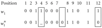
Another example is given as follows:
Position 1 2 3 4 5 6 7 8 9 10 11 12
1
w 0 0 1 1 0 0 0 1 1 0 1 1
1
w∗ 0 0 1 _ 0 0 0 0 1 1 0 1 0
We can see that a deletion error, an insertion error and a substitution error occur at position 4, between 7 and 8 and at position 12, respectively.
Due to IDS errors,w∗1 at the extraction end may take
a very different form from w1. Traditional ECC schemes,
such as BCH coding [10], is not appropriate for IDS
channels because they have no ability to resynchronize
bits. Some efforts have been made in order to solve this
problem. For example, low density parity coding (LDPC)
is used to resynchronize the message [28, 29]. But prior
possibilities are needed in these schemes, which are not
possible in watermarking applications. In [12], ECC based
on repetition coding and HDB3 are proposed to tackle bit desynchronization. However, because of the sensitivity of
HDB3, error propagation may occur during the decoding process which would damage all the trailing watermark bits.
In [14], another ECC based on repetition coding is proposed.
However, if approximate alignment is not achieved, error propagation would also damage all the trailing watermark bits.
In this paper we carefully design an ECC scheme
calledrepetition-header coding (RHC), with great ability to
resynchronize bits. The experimental results show that it has very good robustness against IDS channels.
The original binary watermark w first goes through
repetition coding. Then a header is repeatedly inserted into
the repetition codes to obtain the encoded watermark w1.
The structure of the encoded watermarkw1is illustrated in
Figure 6.
The headers are used to indicate the boundaries of the repetition codes and prevent error propagation in the
decoding process. It must have a different form from the
0 20 40 60 80 100
A
ccur
acy
(%)
0.7 0.8 0.9 1 1.1 1.2 1.3 Scaling factor
Classical
0 20 40 60 80 100
A
ccur
acy
(%)
0.7 0.8 0.9 1 1.1 1.2 1.3 Scaling factor
Blues
0 20 40 60 80 100
A
ccur
acy
(%)
0.7 0.8 0.9 1 1.1 1.2 1.3 Scaling factor
Country
0 20 40 60 80 100
A
ccur
acy
(%)
0.7 0.8 0.9 1 1.1 1.2 1.3 Scaling factor
Disco
0 20 40 60 80 100
A
ccur
acy
(%)
0.7 0.8 0.9 1 1.1 1.2 1.3 Scaling factor
Hiphop
0 20 40 60 80 100
A
ccur
acy
(%)
0.7 0.8 0.9 1 1.1 1.2 1.3 Scaling factor
Jazz
0 20 40 60 80 100
A
ccur
acy
(%)
0.7 0.8 0.9 1 1.1 1.2 1.3 Scaling factor
Metal
0 20 40 60 80 100
A
ccur
acy
(%)
0.7 0.8 0.9 1 1.1 1.2 1.3 Scaling factor
Pop
0 20 40 60 80 100
A
ccur
acy
(%)
0.7 0.8 0.9 1 1.1 1.2 1.3 Scaling factor
Speech Figure11: Robustness against pitch-invariant TSM.
Table1: Distortion.
Classical Blues Country Hiphop Jazz Metal Pop Speech
Average SNR (db) 18.2 20.1 21.1 24.8 25.2 24.2 21.6 22.3
Average ODG −1.04 −0.65 −0.62 −0.31 −0.11 −0.33 −0.57 −0.48
For example, suppose the original watermarkwis 1001,
the repetition time is 20 and the header length is 10. Then the
encoded watermarkw1would be:
w= 1001 =>
w1=1010101010 11111111111111111111
1010101010 00000000000000000000
1010101010 00000000000000000000
1010101010 11111111111111111111
1010101010
(9)
The parts underlined are the repetition codes of the original
watermark bits. “1010101010” is the header. w1 is then
embedded into the audio.
The decoding process is as follows.
(1) Differential ofw1∗to obtainD(i):
D(i)=w1∗(i+ 1)−w∗1(i). (10)
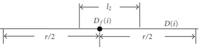
(2) Bit filtering based on theK Nearest Neighbour Rule
(KNNR) is applied onD(i) to obtainDf(i) by (11).
According to KNNR, whether a bit is “1” or “0”
Table2: Robustness to Stirmark attacks (Watermark length=10).
Attack Classical Blues Country Disco Hiphop Jazz Metal Pop Speech
addbrumm 100 0 0 0 0 0 0 0 0 0
addbrumm 1100 0 0 0 0 0 0 0 0 0
addbrumm 2100 0 0 0 0 0 0 0 0 0
addbrumm 3100 0 0 0 0 0 0 0 0 0
addbrumm 4100 0 0 0 0 0 0 0 0 0
addbrumm 5100 0 0 0 0 0 0 0 0 0
addbrumm 6100 0 0 0 0 0 0 0 0 0
addbrumm 7100 0 0 0 0 0 0 0 0 0
addbrumm 8100 0 0 0 0 0 0 0 0 0
addbrumm 9100 0 0 0 0 0 0 0 0 0
addbrumm 10100 0 0 0 0 0 0 0 0 0
addfftnoise — — — — — — — — —
addnoise 100 0 0 0 0 0 0 0 0 0
addnoise 300 0 0 0 0 0 0 0 0 0
addnoise 500 0 0 0 0 0 0 0 0 0
addnoise 700 0 0 0 0 0 0 0 0 0
addnoise 900 0 0 0 0 0 0 0 0 0
addsinus 0 0 0 0 0 0 0 0 0
amplify 0 0 0 0 0 0 0 0 0
compressor 0 0 0 0 0 0 0 0 0
copysample 0 0 — 0 0 0 — 0 0
cutsamples 0 0 0 0 0 0 0 0 0
dynnoise 0 0 0 0 0 0 0 0 0
echo — — — — — — — — —
exchange 0 0 0 0 0 0 0 0 0
extrastereo 30 0 0 0 0 0 0 0 0 0
extrastereo 50 0 0 0 0 0 0 0 0 0
extrastereo 70 0 0 0 0 0 0 0 0 0
fft hlpass 0 0 0 0 0 0 0 0 0
fft invert — — — — — — — — —
fft real reverse 0 0 0 0 0 0 0 0 0
fft stat1 — — — — — — — —
fft test — — — — — — — —
flippsample 0 — 0 0 0 0 — 0 0
invert — — — — — — — — —
lsbzero 0 0 0 0 0 0 0 0 0
normalize 0 0 0 0 0 0 0 0 0
nothing 0 0 0 0 0 0 0 0 0
original 0 0 0 0 0 0 0 0 0
rc highpass 0 0 0 0 0 0 0 0 0
rc lowpass 0 0 0 0 0 0 0 0 0
smooth 0 0 0 0 0 0 0 0 0
smooth2 0 0 0 0 0 0 0 0 0
stat1 0 0 0 0 0 0 0 0 0
stat2 0 0 0 0 0 0 0 0 0
voiceremove — — — — — — — — —
zerocross 0 0 0 0 0 0 0 0 0
zerolength 0 0 0 0 0 0 0 0 0
0 20 40 60 80 100 A ccur acy (%)
0.7 0.8 0.9 1 1.1 1.2 1.3 Scaling factor Classical 0 20 40 60 80 100 A ccur acy (%)
0.7 0.8 0.9 1 1.1 1.2 1.3 Scaling factor Blues 0 20 40 60 80 100 A ccur acy (%)
0.7 0.8 0.9 1 1.1 1.2 1.3 Scaling factor Country 0 20 40 60 80 100 A ccur acy (%)
0.7 0.8 0.9 1 1.1 1.2 1.3 Scaling factor Disco 0 20 40 60 80 100 A ccur acy (%)
0.7 0.8 0.9 1 1.1 1.2 1.3 Scaling factor Hiphop 0 20 40 60 80 100 A ccur acy (%)
0.7 0.8 0.9 1 1.1 1.2 1.3 Scaling factor Jazz 0 20 40 60 80 100 A ccur acy (%)
0.7 0.8 0.9 1 1.1 1.2 1.3 Scaling factor Metal 0 20 40 60 80 100 A ccur acy (%)
0.7 0.8 0.9 1 1.1 1.2 1.3 Scaling factor Pop 0 20 40 60 80 100 A ccur acy (%)
0.7 0.8 0.9 1 1.1 1.2 1.3 Scaling factor
Speech Figure12: Robustness against PSM.
Table3: Robustness to cropping (Watermark length=10).
Time cropped Result Time cropped Result
1% 1010011010 6% 101001 010
2% 1010111010 7% 101001 010
3% 101011 010 8% 101001 010
4% 101001 010 9% 101001 010
5% 101001 010 10% 101001 010
K/2 samples are “1”, this bit is considered as “1”;
otherwise it is considered as “0”, as illustrated in (10) andFigure 7(Here we use the letterrinstead ofK;r is called the filtering diameter).
Df(i)=
⎧ ⎨ ⎩
1 if (t > z)
0 if (t≤z), (11)
wherez= r/2 , andt=jj==ii−+zzD(j).
(3) Suppose the starting and ending position of the
ith consecutive “0” sequence in Df are pStart and
pEnd, respectively. Then w∗(i) is extracted from
w∗1(pStart:pEnd) according to (12).Liis the length
of this “0” sequence andtis the number of bits “1” in
w∗1(pStart:pEnd).
w∗(i)=
⎧ ⎪ ⎪ ⎪ ⎪ ⎪ ⎨ ⎪ ⎪ ⎪ ⎪ ⎪ ⎩ 1 if t > Li 2 0 if t≤ Li 2 . (12)
Let us take the abovew=1001 as an example. The repetition
time is 20 and the header length is 10. Suppose the watermarked audio is modified during transmission and
some IDS errors occur. Then the extracted watermark w∗1
0.85 0.9 0.95 1 1.05 1.1 1.15 1.2
Scaling
fact
or
1 2 3 4 5 6 7 8 9
Groups
Linear TSM
0.85 0.9 0.95 1 1.05 1.1 1.15 1.2
Scaling
fact
or
1 2 3 4 5 6 7 8 9
Groups
Pitch-invariant TSM
0.85 0.9 0.95 1 1.05 1.1 1.15 1.2
Scaling
fact
or
1 2 3 4 5 6 7 8 9
Groups
PSM
Figure13: Average upper and lower bounds, watermark length= 10.
or insertion errors marked by bold and deletion errors marked by underlines)
w1∗=1010111010 111111111011111011111
100101010 00000110000000000000 010101010
0001000000000000000 10101010010
111111111001111111 1010101010
(13)
The decoding process is as follows.
(1) CalculateD(i) according to (10). We get
0.85 0.9 0.95 1 1.05 1.1
Scaling
fact
or
1 2 3 4 5 6 7 8 9
Groups Linear TSM
0.85 0.9 0.95 1 1.05 1.1
Scaling
fact
or
1 2 3 4 5 6 7 8 9
Groups
Pitch-invariant TSM
0.85 0.9 0.95 1 1.05 1.1
Scaling
fact
or
1 2 3 4 5 6 7 8 9
Groups PSM
Figure14: Average upper and lower bounds. o: Watermark length
=20,∗: Watermark length=40.
D(i)=111100111 100000000110000110000
010111111 000001010000000000000
11111111 0001100000000000000
11111111011 100000000101000000
0111111111
(14)
(2) Bit filtering. Here suppose r =8. Let us take the
underlinedD(5)=0 for example. According to (11),
t = 7 > z = 4 which means thatDf(5) = 1. We
Df(i)
r/2 r/2
D(i)
l2
Figure15: Bit filtering whenl2< r/2.
nearby correct bits. Then we obtain:
Df =111111111 000000000000000000000
000111111 000000000000000000000
11111111 0000000000000000000
11111111111 100000000000000000
0111111111
(15)
We see that the consecutive “1” sequences indicate the approximate positions of the header and the consecutive “0” sequences indicate the approximate positions of the repetition codes.
(3) The starting and ending position (the underlined bits) of the 1st 0-sequence is 10 and 33,
respec-tively, in the above Df. So L1 = 24. The
corresponding segment in w∗1 is w1∗(10 : 33):
011111111101111101111110. Then here t = 20 >
L1/2 = 12. According to (12), w∗(1) = 1. The
same rule is applied to the rest of the sequences and
we obtainw∗=1001, which is identical to the original
watermarkw.
Here we present an experimental result inFigure 8.w=
[1 0 1 0 0]. Repetition timel1 = 400 and header length
l2=200. After embedding, a linear TSM (scale factor 1.1) is
applied to the watermarked clip. FromFigure 8we can see
that w∗1 is quite different from w1 due to the IDS errors.
And D is so noisy that it is impossible to distinguish the
boundaries of the repetition codes. However, Df, the
bit-filtered version ofD, very clearly indicates the locations of
the repetition codes (compareDf withw1), and thus it can
be used to recover the final watermarkw∗fromw∗1.
There exists a problem with choosing the values for the
repetition time l1, the header length l2 and the filtering
diameter r. We outline a model for these parameters in
Appendix B. In our algorithmr =l2 andl2= l1/2 have the best performance according to experiments.
4. Experimental Results
In the experiments, we tested 900 audio clips. They are divided into nine groups: classical, blues, country, disco, hiphop, jazz, metal, pop, and speech, numbered as groups 1 to 9. Each group consists of 100 clips. The group of classical clips consists of various musical instruments. The group of speech consists of news reports and dialogues.
Other groups consist of different human voices with different
backgrounds for entertainment. All clips are of wav format, 44.1 k sampling rate, 16-bit quantization, mono. db2 is selected as the wavelet basis. The wavelet decomposition level is 3 for classical and 5 for the other groups. The program is run in Matlab 7. The attacks we consider here are temporally linear TSM, pitch-invariant TSM and PSM, along with others such as cropping, jittering, MP3, resampling, requantization, and Stirmark for Audio.
4.1. Embedding Distortion. In the embedding process, the distortion relies on the widths of Shape-A and Shape-B, the
number of bits inw1 and the DYWT decomposition level.
The widths of the two shapes are the embedding strength. The larger the widths, the more samples are modified and the more robust will be the watermark with greater distortion.
The number of bits in w1 is the product of the original
watermark length and (l1 + l2). The larger l1, and l2 are,
the greater the robustness and distortion will be. Therefore we can adjust the above parameters to an acceptable balance between distortion and robustness. In the experiments we
embedded a watermark of 10 bits, and adoptedl1=200 and
l2=100 when the distortion and robustness are balanced.
In the proposed algorithm, the embedded bits are located by the peak widths and the bit decision is made according to the peak height. Therefore the performance of the algorithm is based on the fluctuations of the embedding domain. If the
embedding domain is too flat, it will be difficult to embed
the watermark bits; the robustness will be weak as well. From Figure 9(a)we can see that as the decomposition level grows,
the waveform of DYWT coefficients becomes flatter and
flatter. So the decomposition level should not be too large.
On the other hand, the degradation of quality is affected
by the decomposition level. The smaller the decomposition level, the greater the distortion will be. So the decomposition
level should not be too small. As a result there is a trade-off.
In the experiments, we found that a decomposition level of 5 was acceptable for most of the audio clips when robustness, distortion and capacity were taken into account. But for the classical group, the robustness was not as good as other groups. The reason lies in the fact that the waveform of 5 level
decomposition coefficients is flatter than the other groups as
shown inFigure 9(b)where we intercept and present a short
segment of the 5 level DYWT decomposition coefficients
from a classical and a jazz clip, respectively. Therefore, for the classical group, we reduced the decomposition level to 3 so that a good robustness was achieved.
We tested the distortion with values of SNR and objective
difference grade (ODG). The SNR value can reflect the
degree of modification brought by the watermarking while the ODG value reflects the human auditory system (HAS) model to show the distorted degree of audio frames. According to the requirement of the International Federation of the Phonographic Industry (IFPI), the SNR value should
be higher than 20 dB [20]. The ODG value can be mapped to
the following description [30]: 0 (insensitive),−1 (audible),
−2 (slightly annoying),−3 (annoying),−4 (very annoying),
and −5 (catastrophic). The value of OGD is obtained by
Table4: Robustness to jittering (Watermark length=10).
Jittering classical blues Country disco hiphop jazz metal pop speech
−(1:15) 0 0 0 0 0 0 0 0 0
−(1:11 0 0 0 0 0 0 0 0 0
−(1:10) — 0 0 — 0 0 0 — 0
−(1:8) — — — — 0 — 0 — —
−(1:5) — — — — — — — — —
+(1:15) 0 0 0 0 0 0 0 0 0
+(1:11) 0 0 0 0 0 0 0 0 0
+(1:10) 0 0 0 0 0 0 0 0 0
+(1:8) 0 0 0 0 0 0 0 0 —
+(1:5) — — — — 0 — 0 — —
FromTable 1, we can see that the watermark is imper-ceptible in most of the clips since most of the SNRs are over
20 db and the ODGs are between –1∼0. But for classical,
the audio quality shows a slight degradation because the decomposition level for this group is 3. We can reduce the distortion by reducing the watermark length, the repetition times or the header length. For example, when we embed a shorter watermark (5 bits) in the 5 level decomposition DYWT, it becomes inaudible, but, for clarity, we still chose to present the results when all the parameters except the decomposition level were the same.
4.2. Robustness Test
4.2.1. Robustness to TSM and PSM. In Figures 10–12 we present the robustness to linear TSM, pitch-invariant TSM
and PSM, when the scale factors range from 0.7 to 1.3 (±30%
scaling). The vertical axis, accuracy, is the percentage of
clips from which w∗ is the same as w. Since each group
consists of 100 clips, N% means the watermark can be
completely recovered fromNaudio clips without any errors
in this group. From Figure 10, we see that in the classical
group, when the linear TSM scale factors are within [0.85, 1.15] the accuracy is almost 100%, that is the watermark is completely recovered from almost all of the clips. And when the scale factors are within [0.8, 1.26] the accuracy is more than 80%, meaning that the watermark survives in more than 80% of the clips. We can also see that for
different audio clips, the degree of tolerance of the watermark
is different. For example, in the classical group, for some
audio clips the watermark can resist 0.7 or 1.3 scaling; but for some others only around 0.85 or 1.15 at most. For
one clip, if the watermark can survive within [N1, N2],
N1 and N2 are called the lower bound and upper bound,
respectively. We compute the average lower bound and
upper bound for each group, and present them inFigure 13.
We see that, statistically, the watermark can resist scaling
within [0.87, 1.16] ([−13%, +16%]) in the classical group.
For other groups, the average lower bounds are between 0.86 and 0.9, and the average upper bounds are around 1.16. The average scaling tolerance for linear TSM is around
[0.88, 1.16] ([−12%, +16%]) statistically, which means that
our algorithm is robust to linear TSM.
Similar results are shown in Figures 11 and 12 with
respect to pitch-invariant TSM and PSM. From Figure 13,
we see that, statistically, the watermark can resist
pitch-invariant TSM of around [0.86, 1.12] ([−14%, +12%]) and
PSM of around [0.88, 1.12] ([−12%, +12%]), which means
that our algorithm is also robust against these two kinds of scaling.
The robustness depends on the similarity of Set A and Set B and on the RHC scheme. We observed one clip in the speech group where the temporally linear TSM reaches 0.82
(−18%) and found that the intersection of Set A and Set B
is as high as around 60%. That is around 60% bits of w∗1
are extracted from the watermarked peaks; the other 40% bits are extracted from the un-watermarked peaks. Many IDS errors occur during scaling. But our specially designed RHC decoder successfully fixes these desynchronization errors and recovers the original watermark. However when the scaling
reaches 0.8 (−20%), the intersection of Set A and Set B is
only around 40%. The IDS errors are too serious to erase and the RHC decoder cannot recover the correct watermark from w∗1.
In conclusion, our algorithm is robust against both TSM and PSM. On the contrary no other scheme reported so far in the literature can overcome both TSM and PSM, as stated inSection 2. For example, [16,20] can only deal with TSM, but are unable to overcome PSM. In this paper, we solve this problem by the invariant features of DYWT, the robust embedded methods and the RHC scheme.
In the above scaling, the original watermark contains 10
bits,l1 = 200 andl2 = 100. We now change these values:
(1) watermark length = 20, l1 = 100 and l2 = 50; (2)
watermark length=40,l1 = 50 andl2 = 25. The average
upper and lower bounds are shown inFigure 13. Statistically,
the average tolerances for the nine groups of linear TSM, pitch-invariant TSM and PSM are [0.895, 1.112], [0.914,
1.095], [0.910, 1.099] (watermark length=20) and [0.924,
1.08], [0.935, 1.078], [0.932, 1.069] (watermark length =
40). That is, the watermark can resist scaling of about±10%
when the watermark capacity is 2 bps and about±8% when
the capacity is 4 bps. Although, statistically, the robustness is good, the watermark may be fragile in some particular audio
clips. For example, fromFigure 14, we see that the robustness
Table5: Comparison with other algorithms.
Algorithm Capacity Robustness to TSM Robustness to PSM Robustness to other attacks
[12] 2.3 bps Around±8% Unreported Unreported
[16] 4.2 bps
Pitch-invariant TSM of around
±7%, but susceptible to linear
TSM
Susceptible to PSM Unreported
[20] 3 bps
Pitch-invariant TSM of around
±20%, and linear TSM of
around±10%
Susceptible to PSM
Susceptible to MP3 compression: errors occur under the smallest compression ratio.
[23] Unreported Susceptible to TSM BER is around 13% when scaling
factors are±10%
Robust to compression ratio of 11.
Ours 1 bps–4 bps
Pitch-invariant TSM of around
[−14%,+12%], and linear TSM
of around [−12%, +16%] at a
capacity of 1bps;±10% and±8%
at 2 bps and 4 bps, respectively.
PSM of around [−12%, +12%]
at a capacity of 1 bps;±10% and
±8% at 2 bps and 4 bps,
respectively.
Very robust to MP3 compression even under the largest
compression ratio 22.05.
different properties of the audio signals into the algorithm
is a major challenge in the future.
4.2.2. Robustness against Stirmark for Audio. Stirmark for Audio is a benchmark software in audio watermarking. We
present the results for one clip from each group inTable 2.
“0” denotes that w∗ is the same as w. And “—” denotes thatw∗ is different from w. We can see that the watermark is robust against most attacks. But the watermarked audio
signal is made very noisy by some attacks, such as “fft noise”,
“fft stat1”, “fft test”, “echo” and “voicerremove”. The SNR
val-ues after these attacks all drop to 2∼4 db, which means that
the attacked audio is totally destroyed and it is reasonable
that the watermark is erased. “invert” attack also destroys
the watermark because it inverts the whole waveform of the signal so that the peaks become the troughs and the troughs become the peaks. As the watermarked peaks are
changed into troughs by the “invert” attack, the watermark
becomes undetectable if we search the peaks for embedded bits. However, this is not a big problem. The solution is to search the troughs if we fail to extract the watermark from the peaks or to revise the embedding algorithm so that the watermark bits are embedded into the widest peaks and troughs.
4.2.3. Robustness to Cropping and Jittering. Now randomly selected portions of the clips are cropped. As the results for
all clips are similar, we show inTable 3the results for a
sym-phony clip from the classical group. It can resist 2% cropping. By comparing with the original watermark 1010011010, we can see that the error propagation is restricted, that is, lost watermark bits are limited within the cropped portion, but the other watermark bits in the remaining parts are not
affected. If the cropped portion contains no watermark bits,
the watermark can be completely recovered.
We also performed jittering on the clips and show the
results for one clip from each group inTable 4, from which
we can see that the watermark is robust to jittering of
around±(1 : 10). That is, when 1 sample is copied into or
cut offfrom every 10 samples the watermark still survives.
Compared with [20], in which the watermark can resist±(1 :
50) jittering, our algorithm has a much better performance.
4.2.4. Robustness against Other Common Operations. MP3 compression ratios are 5.5 (128 kbps), 7.4 (96 kbps), 8.8 (80 kbps), 11.0 (64 kbps), 12.6 (56 kbps), 14.7 (48 kbps), 17.64 (40 kbps), 22.05 (32 kbps). The watermark (10 bits) cannot survive from 45 clips, 5% of the 900 clips, when the compression ratio is 22.05. The watermark survives in
all clips subjected to re-sampling (44.1 k → 11.025 k →
44.1 k) and re-quantization (16 bits→8 bits →16 bits). The
watermark is very robust against these operations because, basically, MP3, re-sampling and requantization cause little geometrical desynchronization and they do not pose big challenges to audio watermarking.
4.3. Comparison with Other Reported Efforts. FromTable 5, we can see that other algorithms cannot resist TSM or PSM because the domains for data embedding do not
have invariant properties. For example, in [16], the data is
embedded in the FFT domain of the DWT coefficients. If the
frequency components are changed by PSM modifications,
the watermark would be lost. In [20], data is embedded by
modifying the relationship between the sample values in the time domain. However PSM would seriously damage such
a relationship. In [23], the extraction process is based on
the assumption that the time duration remains unchanged. So when the time duration is changed by TSM or tempo-variant PSM, the watermark would become undetectable. In our algorithm, the DYWT has invariant properties both to TSM and PSM, which help retain the watermark.
5. Discussion and Conclusion
proposed in this paper. The main contributions are listed as follows.
(1) The DYWT is examined thoroughly by theoretical deduction and extensive experiments. Based on the analysis, we conclude that the DYWT has very good geometrical invariance compared with DWT, DCT and DFT.
(2) Resynchronization is achieved by utilizing the geo-metrical invariance of the DYWT. The widest peaks
of the DYWT coefficients are selected to embed the
watermark bits. At the receiving end, the widest peaks are considered as containing the watermark
bits. Experimental results show that this is an effective
way to identify the watermarked positions. A novel
embedding method using two different waveforms
to represent the bits “0” and “1” is proposed. Blind detection is realized.
(3) We also design a special ECC scheme called RHC that significantly helps to recover the watermark and restricts error propagation due to IDS errors.
(4) The proposed algorithm is very robust against desyn-chronization attacks such as TSM, PSM, jittering, cropping, other common audio processing and Stir-mark for Audio. It also has the best performance
compared with other reported efforts as shown in
Table 5.
However, there exist some issues that must be noted and solved in the future.
(1) InAppendix B, the analysis of (B.1)–(B.3) is based
on the deletion error only, regardless of insertion and deletion. In future work a more sophisticated model of IDS errors will be formulated.
(2) The values of parameters such as r, l1, l2 and the
decomposition level are not determined adaptively. In future work, the algorithm will be refined so that these values can be chosen adaptively. The solution
is to integrate the properties of different kinds of
audio signal into the algorithm so that these values can balance the distortion and robustness
Appendices
A.
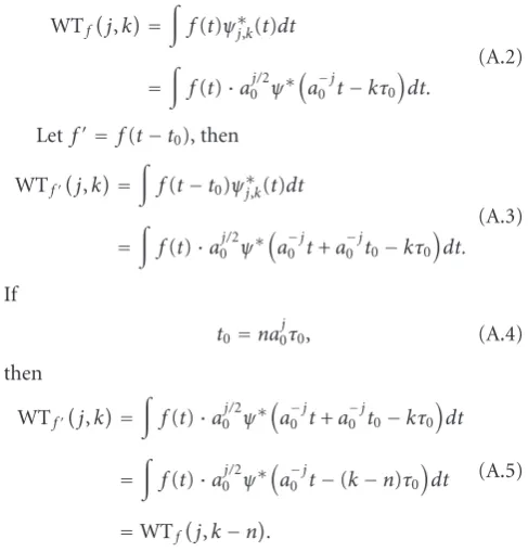
We prove the time-shift properties of DWT as follows:
If the steps along the vertical axis and the time axis area0
andτ0, the DWT wavelet can be expressed as
ψj,k(t)=a−0j/2ψ
a−0jt−kτ0
. (A.1)
Suppose WTf(j,k) are the DWT coefficients of f(t).
Then
WTf
j,k=
f(t)ψ∗j,k(t)dt
=
f(t)·a0j/2ψ∗
a−0jt−kτ0
dt.
(A.2)
Let f= f(t−t0), then
WTfj,k=
f(t−t0)ψ∗j,k(t)dt
=
f(t)·a0j/2ψ∗
a−0jt+a −j
0 t0−kτ0
dt. (A.3)
If
t0=na0τ0j , (A.4)
then
WTfj,k=
f(t)·a0j/2ψ∗
a−0jt+a −j
0 t0−kτ0
dt
=
f(t)·a0j/2ψ∗
a−0jt−(k−n)τ0
dt
=WTf
j,k−n.
(A.5)
We can see from (A.5) that, when condition (A.4) holds, the
jth level DWT coefficients will be shiftednpositions. We also
know that for an audio signal of sampling frequencyFto be
formed by the DWT, τ0 = 1/F. Suppose that t0 = N/F,
that is, the audio signal is shifted N positions, then from
condition (A.4) we get
N=n·a0j. (A.6)
From the above, we can show that if the audio signal is shifted
Npositions andNmeets condition (A.6), itsjth level DWT
coefficients will be shiftednpositions in the same direction.
In the case of a two filter DWT,a0 =2. Condition (A.6) is
then as follows:
N=n·2j. (A.7)
B.
Regardless of insertion and deletion errors, and in connec-tion with substituconnec-tion errors only, we suppose the probability
of a substitution error in every bit to bepand that one bit is
independent of another.X is a random variable that stands
for the number of erroneous bits inw1∗ before theKNNR
decision. Then we obtain
P{X=k} =Cknpk
1−pn−k. (B.1)
Then the probability of a correct decision is
P
X < r 2
=
r/2−1
k=0
P{X=k}
=
r/2−1
k=0 Ck
npk
1−pn−k,
We now suppose thatλ=r·pis a constant andr≥20. From the Poisson Theory, we further obtain
P
X < r 2
≈
r/2−1
k=0 λke−λ
k! . (B.3)
Letλ=5. Ifr≥27,P{X < r/2}will be larger than 1−10−2; ifr≥41,P{X < r/2}will be larger than 1−10−6.
Moreoverl2≥r/2 must hold. Otherwise, the consecutive
“0” sequence inDmay probably be eliminated because part
of the filtering window outside the 0-sequence is longer than the part inside it, as illustrated inFigure 15.
References
[1] J. Dittmann, A. Mukherjee, and M. Steinebach, “Media-independent watermarking classification and the need for combining digital video and audio watermarking for media
authentication,” inProceedings of the International Conference
on Information Technology: Coding and Computing, pp. 62–67, Las Vegas, Nev, USA, 2002.
[2] F. Deguillaume, S. Voloshynovskiy, and T. Pun, “Method for the estimation and recovering from general affine transforms
in digital watermarking applications,” inSecurity and
Water-marking of Multimedia Contents IV, vol. 4675 ofProceedings of
SPIE, pp. 313–322, San Jose, Calif, USA, 2002.
[3] J. J. K. O’Ruanaidh and T. Pun, “Rotation, scale and translation
invariant spread spectrum digital image watermarking,”Signal
Processing, vol. 66, no. 3, pp. 303–317, 1998.
[4] G. W. Braudaway and F. Mintzer, “Automatic recovery of invisible image watermarks from geometrically distorted
images,” inSecurity and Watermarking of Multimedia Contents
I, vol. 9 ofProceedings of SPIE, pp. 3971–483, 2000.
[5] S. Pereira and T. Pun, “Robust template matching for affine
resistant image watermarks,” IEEE Transactions on Image
Processing, vol. 9, no. 6, pp. 1123–1129, 2000.
[6] C.-Y. Lin, M. Wu, J. A. Bloom, I. J. Cox, M. L. Miller, and Y. M. Lui, “Rotation, scale, and translation resilient watermaking for
images,”IEEE Transactions on Image Processing, vol. 10, no. 5,
pp. 767–782, 2001.
[7] X. Kang, J. Huang, Y. Q. Shi, and Y. Lin, “A DWT-DFT com-posite watermarking scheme robust to both affine transform
and JPEG compression,”IEEE Transactions on Circuits and
Systems for Video Technology, vol. 13, no. 8, pp. 776–786, 2003. [8] L. Cai and S. Du, “Rotation, scale and translation invariant image watermarking using Radon transform and Fourier
transform,”Proceedings of the IEEE 6th Circuits and Systems
Symposium on Emerging Technologies: Frontiers of Mobile and Wireless Communication, vol. 1, pp. 281–284, 2004.
[9] Y. Xin, S. Liao, and M. Pawlak, “Geometrically robust image
watermarking via pseudo-Zernike moments,” inProceedings of
the Canadian Conference on Electrical and Computer
Engineer-ing, vol. 2, pp. 939–942, 2004.
[10] J. Huang and Y. Wang, “A blind audio watermarking algorithm
with self-synchronization,” inProceedings of the IEEE
Interna-tional Symposium on Circuits and Systems, vol. 3, pp. 627–630, 2002.
[11] M. F. Mansour and A. H. Tewfik, “Data embedding in audio
using time-scale modification,”IEEE Transactions on Speech
and Audio Processing, vol. 13, no. 3, pp. 432–440, 2005. [12] M. F. Mansour and A. H. Tewfik, “Time-scale invariant audio
data embedding,”IEEE Transactions on Multimedia, vol. 3, no.
2, pp. 232–241, 2001.
[13] “SDMI Phase II Screening Technology Version 1.0,” February
2000,
http://www.usenix.org/publications//library/proceed-ings/sec01/craver.pdf.
[14] Y. Wang, S. Wu, and J. Huang, “Audio watermarking robust to geometrical distortions based on dyadic wavelet transform,” inSecurity, Steganography, and Watermarking of Multimedia Contents IX, vol. 6505 ofProceedings of SPIE, San Jose, Calif, USA, 2007.
[15] W. Li and X. Xue, “Audio watermarking based on music content analysis: robust against time scale modification,” inProceedings of the 2nd International Workshop on Digital Watermarking (IWDW ’04), pp. 13–33, Seoul, South Korea, October 2004.
[16] W. Li, X. Xue, and P. Lu, “Localized audio
watermark-ing technique robust against time-scale modification,”IEEE
Transactions on Multimedia, vol. 8, no. 1, pp. 60–69, 2006. [17] L. Cui, S. Wang, and T. Sun, “The application of binary
image in digital audio watermarking,” in Proceedings of
the International Conference on Neural Networks and Signal Processing, vol. 2, pp. 1497–1500, 2003.
[18] L. Cui, S. Wang, and T. Sun, “The application of wavelet analysis and audio compression technology in digital audio
watermarking,” inProceedings of the International Conference
on Neural Networks and Signal Processing, vol. 2, pp. 1533– 1537, 2003.
[19] W. Li, X. Xue, X. Li, and P. Lu, “A novel feature-based robust
audio watermarking for copyright protection,” inProceedings
of the International Conference on Information Technology: Coding and Computing [Computers and Communications], vol. 2, pp. 554–558, April 2003.
[20] S. Xiang and J. Huang, “Histogram-based audio watermarking
against time-scale modifications and cropping attacks,”IEEE
Transactions on Multimedia, vol. 9, no. 7, pp. 1357–1372, 2007. [21] X. Wang, W. Qi, and P. Niu, “A new adaptive digital audio
watermarking based on support vector regression,” IEEE
Transactions on Audio, Speech and Language Processing, vol. 15, no. 8, pp. 2270–2277, 2007.
[22] H.-Y. Liu, X. Zheng, and Y. Wang, “DWT-based audio
watermarking resistant to desynchronization,” inProceedings
of the 27th IEEE International Conference on Computer and Information Technology, pp. 745–748, 2007.
[23] L. Li, J. Hu, and X. Fang, “Spread-spectrum audio watermark
robust against pitch-scale modification,” inProceedings of the
IEEE International Conference on Multimedia and Expo (ICME
’07), pp. 1770–1773, 2007.
[24] S. Wu, J. Huang, D. Huang, and Y. Q. Shi, “Efficiently self-synchronized audio watermarking for assured audio data
transmission,”IEEE Transactions on Broadcasting, vol. 51, no.
1, pp. 69–76, 2005.
[25] J. Laroche, “Time and pitch scale modification of audio
signals,” inApplications of Digital Signal Processing to Audio
and Acoustics, M. Kahrs and K. Brandenburg, Eds., Kluwer Academic Publishers, Norwell, Mass, USA, 1998.
[26] R. J. McAulay and T. F. Quatieri, “Speech analysis/synthesis
based on a sinusoidal representation,”IEEE Transactions on
Acoustics, Speech and Signal Processing, vol. 34, no. 4, pp. 744– 754, 1986.
[27] http://www.psbspeakers.com/audio-topics/The-Frequencies-of-Music.
[28] M. C. Davey and D. J. C. MacKay, “Reliable communication over channels with insertions, deletions, and substitutions,”
[29] M. F. Mansour and A. H. Tewfik, “Convolutional codes for channels with substitutions, insertions, and deletions,” in
Proceedings of the IEEE Global Telecommunications Conference, vol. 2, pp. 1051–1055, 2002.
[30] M. Steinebach, S. Zmudzinski, and T. Bolke, “Audio
water-marking and partial encryption,” inSecurity, Steganography,
and Watermarking of Multimedia Contents VII, vol. 5681 of