88 | P a g e
www.ijarse.com
DYNAMIC VOLTAGE RESTORER AGAINST
BALANCED AND UNBALANCED VOLTAGE
SAG/SWELLS: MODELLING AND SIMULATION
1
Abhay Kr.Shah ,
2Mohd.Shahid,
3Pradeep Bhardwaj
1M. Tech-(Power System)-Student,
2Asst. Prof,
Department of Electrical & Electronics Engineering, Al-Falah School Of Engineering & Technology,
(An Autonomous Institution) Dhauj Faridabad Haryana (India)
3
Asst. Prof.,Department of Electrical Engineering, Greater Noida Institute Of Technology,
Knowledge Park-II, Greater Noida UP (India)
ABSTRACT
This paper describes the problem of voltage sags and swells and its severe impact on non linear loads or
sensitive loads. Severe impacts on Sensitive load itself due to voltage sags and swell. The Dynamic Voltage Restorer (DVR) is fast, flexible and efficient solution to mitigate voltage sag/swell by injecting Voltage as well
as power into the system. Dynamic Voltage Restorer (DVR) is a power costumed device used in power distribution network using for voltage enhancement after occurring disturbance in the power system. The DVR
can restore the load voltage within few milliseconds. The control of the compensation voltages in DVR based on
dqo algorithm is discussed. Dynamic Voltage Restorer (DVR) with sinusoidal pulse width (SPWM) based
controller by using the Mat lab /Simulink verify the performance of the proposed method.
Keywords: DVR, Power Quality, Park’s transformation, Voltage Sags/Swells, VSI, DC Energy
Storage, harmonic distortion.
I INTRODUCTION
One of the major concerns in electricity industry today is power quality problems to sensitive loads. This is due
to the advent of a large numbers of sophisticated electrical and electronic equipment, such as computers,
programmable logic controllers, variable speed drives, and so forth. The use of these equipments very often
requires power supplies with very high quality. Power Quality problems encompass a wide range of
disturbances such as voltage sags/swells, voltage interruption, flicker, harmonics distortion, impulse transient,
and interruptions [1]. Power distribution systems, should ideally provide their customers with an uninterrupted
flow of energy with a smooth sinusoidal voltage at the contracted magnitude level and frequency. However, in
practice, power systems, especially distribution systems, have numerous nonlinear loads, which significantly
affect the quality of the power supply. As a result of these nonlinear loads, the purity of the supply waveform is
89 | P a g e
www.ijarse.com
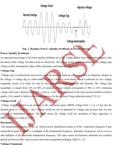
Fig. 1. Regular Power- Quality Problems in Power System
Power Quality Problems
An important percentage of all power quality problems are of the voltage-quality type where what matters is the
deviation of the voltage waveform from its ideal form. The typical power quality disturbances are voltage sags
voltage swells, interruptions, phase shifts, harmonics and transients. [6],[7],[9]
Voltage Sag
Voltage sag is considered the most severe since the sensitive loads are very susceptible to temporary changes in
the voltage.A voltage Sag is a short time (10 ms to 1 minute) event during which a reduction in r.m.s voltage
magnitude occurs. It is often set only by two parameters, depth/magnitude and duration. The voltage Sag
magnitude is ranged from 10% to 90% of nominal voltage (which corresponds to 90% to 10% remaining
voltage) and with a duration from half a cycle to 1 min. It is considered as the most serious problem of power
quality. It is caused by faults in the power system or by the starting of large induction motor [7,8,11].
Voltage Swell
Voltage swell is defined as an increase in the root mean square (RMS) voltage from 1.1 to 1.8 per unit for
duration from 0.5 cycles to 1 min. Voltage swells are not as important as voltage sags because they are less
common in distribution systems. The main causes for voltage swell are switching of large capacitors or
start/stop of heavy loads [12,13].
Harmonics
The fundamental frequency of the AC electric power distribution system is 50 Hz. A harmonic frequency is any
sinusoidal frequency, which is a multiple of the fundamental frequency. Harmonic frequencies can be even or
odd multiples of the sinusoidal fundamental frequency. The main causes for harmonic distortion are rectifiers
and all non-linear loads, such as power electronics equipment including VSDs [7, 13].
Voltage Transients
They are temporary and undesirable voltages that appear on the power supply line. Transients are high
over-voltage disturbances (up to 20kV) that last for a very short time. Flicker: Oscillation of over-voltage value, amplitude
modulated by a signal with frequency of 0 to 30 Hz. The main causes are frequent start/stop of electric motors
(for instance elevators), oscillating loads [14]. Figure -1 shows the sketch of a voltage waveform with physical
90 | P a g e
www.ijarse.com
II
.
OPERATION OF DVR
Dynamic Voltage Restorer is a series connected device designed to maintain a constant RMS voltage value
across a sensitive load.DVR is a Custom Power Device used to eliminate supply side voltage disturbances. The
term custom power refers to the use of power electronics controllers in a distribution system, especially, to deal
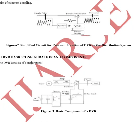
with various power-quality problems. From Figure-2. DVR also known as the Series Voltage Booster (SVB) or
the Static Series Compensator (SSC), is a device that utilizes solid state (or static) power electronic components,
and is connected in series to the utility primary distribution circuit [5]. The DVR maintains the load voltage at a
desired magnitude and phase by compensating the voltage sags/swells and voltage unbalances presented at the
point of common coupling.
Figure-2 Simplified Circuit for Role and Location of DVR in the Distribution System
III DVR BASIC CONFIGURATION AND COMPONENTS
The DVR consists of 6 major parts:
Figure. 3. Basic Component of a DVR
3.1. Voltage Source Inverter (VSI)
Voltage source inverter (VSI) is low voltage and high current with step up injection transformer is used to
boost up the injected voltage. The Voltage Source Inverter (VSI) or simply the inverter, converts the dc voltage
from the energy storage unit (or the dc link) to a controllable three phase ac voltage. The inverter switches are
normally fired using a sinusoidal Pulse Width Modulation (PWM) scheme. Since the vast majority of voltage
sags seen on utility systems are unbalanced, the VSI will often operate with unbalanced switching functions for
the three phases, and must therefore treat each phase independently. Moreover, Sag on one phase may result in a
91 | P a g e
www.ijarse.com
topology of the DVR is the use of multi-inverter system in cascade. This topology will add the voltage of the
single cascaded inverters in series in order to obtain the desired inverter voltage. This method gets rid of the
injection transformer used in the basic configuration of the DVR. This arrangement is often called a
transformer-less or multilevel or a cascade inverter DVR [6-7].
3.2 Injection Transformers
The three single-phase injection transformers are used to inject missing voltage
to the system. The electrical parameters of series injection transformer should be selected correctly to ensure the
maximum reliability and effectiveness [4]. To integrate the injection transformer correctly into the DVR, the
MVA rating, the primary winding voltage and current ratings, the turn-ratio and the short-circuit impedance
values of transformers are required [5].
3.3 Passive Filters
The nonlinear characteristics of semiconductor devices cause distorted waveforms associated with high
frequency harmonics at the inverter output.
Figure. 4. DVR with load side filter
Passive filters are placed at the high voltage side of the DVR to filter the harmonics. These filters are placed at
the high voltage side as placing the filters at the inverter side introduces phase angle shift which can disrupt the
control algorithm [5,9]
3.4 Energy storage
92 | P a g e
www.ijarse.com
It is responsible for energy storage in DC form. Flywheels, batteries, superconducting magnetic energy storage
(SMES) and super capacitors can be used as energy storage devices. It is supplies the real power requirements of
the system when DVR is used for compensation.
3.5 Capacitor
DVR has a large DC capacitor to ensure stiff DC voltage input to inverter
3.6 By-Pass Switch
It is used to protect the inverter from high currents in the presence of faulty conditions. In the event of a fault or
a short circuit on downstream, the DVR changes into the bypass condition where the VSI inverter is protected
against over current flowing through the power semiconductor switches. The rating of the DVR inverters
becomes a limiting factor for normal load current seen in the primary winding and reflected to the secondary
winding of the series insertion transformer. For line currents exceeding the rating, a bypass scheme is
incorporated to protect the power electronics devices [13].
IV CONTROL OF DVR
The basic functions of a DVR controller are the detection of voltage sag/swell events in the system; computation
of the correcting voltage, generation of trigger pulses to the sinusoidal PWM based DC-AC inverter, correction
of any anomalies in the series voltage injection and termination of the trigger pulses when the event has passed.
The controller may also be used to shift the DC-AC inverter into rectifier mode to charge the capacitors in the
DC energy link in the absence of voltage sags/swells. The dqo transformation or Park’s transformation [6-7] is
used to control of DVR. The dqo method gives the sag depth and phase shift information with start and end
times. The quantities are expressed as the instantaneous space vectors. Firstly convert the voltage from abc
reference frame to dqo reference. For simplicity zero phase sequence components is ignored. The detection is
carried out in each of the three phases. The control scheme for
the system is based on the comparison of a
voltage reference and the measured terminal voltage (Va,Vb,Vc)
The voltage sags is detected when the supply drops below 90% of the reference value whereas voltage swells is
detected when supply voltage increases up to 25% of the reference value. The error signal used as a modulation
signal allows to generate a commutation pattern for the power switches (IGBT’s) constituting the voltage source
converter. The commutation pattern is generated by means of the sinusoidal pulse width modulation technique
(SPWM); voltages are controlled through the modulation. The PLL circuit is used to generate a unit sinusoidal
Wave in phase with mains voltage.
93 | P a g e
www.ijarse.com
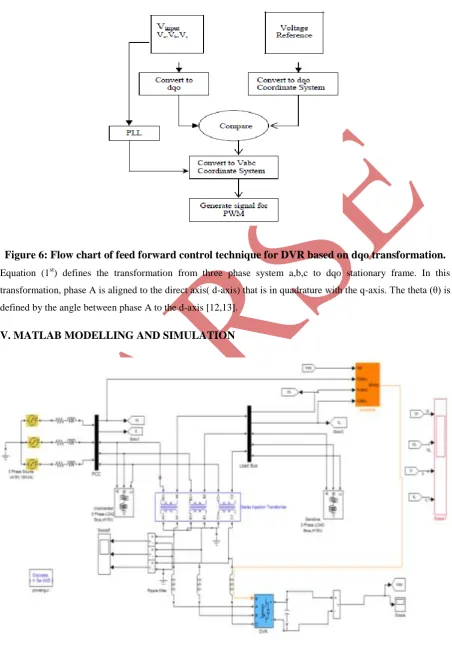
Figure 6: Flow chart of feed forward control technique for DVR based on dqo transformation.
Equation (1st) defines the transformation from three phase system a,b,c to dqo stationary frame. In this
transformation, phase A is aligned to the direct axis( d-axis) that is in quadrature with the q-axis. The theta (θ) is
defined by the angle between phase A to the d-axis [12,13].
V. MATLAB MODELLING AND SIMULATION
94 | P a g e
www.ijarse.com
By using the MAT LAB and its Simulink and Sim Power System toolboxes the DVR is modelled and simulated.
The MAT LAB model of the DVR is shown in figure. The three-phase programmable source is connected to the
three-phase load through the DVR. The load is a lagging power factor load. The VSI of the DVR is connected to
the system using an injection transformer. Also, a ripple filter for filtering the switching ripple in the terminal
voltage is connected across the terminals of the secondary of the transformer. The dc bus capacitor of DVR is
selected based on the transient energy requirement and the dc bus voltage is selected based on the injection
voltage level. The dc capacitor decides the ripple content in the dc voltage.The control algorithm for the DVR is
simulated in MATLAB. The control algorithm shown in Fig.-6 is modelled for DVR control. The reference load
voltages are derived from the sensed terminal voltages, load supply voltages and the dc bus voltage of the DVR.
A pulse width modulation (PWM) controller is used over the reference and sensed load voltages to generate gate
signals for the IGBT’s of the VSI.
VI SIMULATION RESULTS AND DISCUSSION
A detailed simulation of the DVR control system was performing using MATLAB/SIMULINK program in
order to verify the operation. The performance of the DVR is demonstrated for different supply voltage
disturbances such as sag and swells in supply voltage.
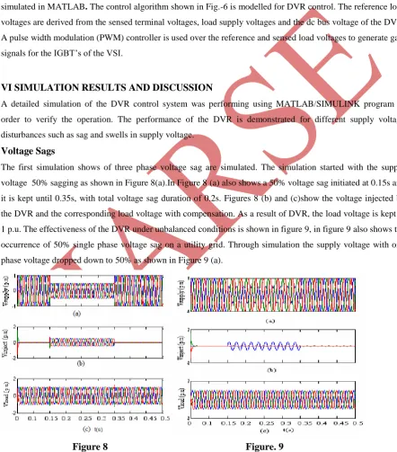
Voltage Sags
The first simulation shows of three phase voltage sag are simulated. The simulation started with the supply
voltage 50% sagging as shown in Figure 8(a).In Figure 8 (a) also shows a 50% voltage sag initiated at 0.15s and
it is kept until 0.35s, with total voltage sag duration of 0.2s. Figures 8 (b) and (c)show the voltage injected by
the DVR and the corresponding load voltage with compensation. As a result of DVR, the load voltage is kept at
1 p.u. The effectiveness of the DVR under unbalanced conditions is shown in figure 9, in figure 9 also shows the
occurrence of 50% single phase voltage sag on a utility grid. Through simulation the supply voltage with one
phase voltage dropped down to 50% as shown in Figure 9 (a).
Figure 8 Figure. 9
Figure 8 Three-phase voltages sag: (a)-Source voltage, (b)-Injected voltage, (c)-Load
95 | P a g e
www.ijarse.com
The DVR injected voltage and the load voltage are shown in Figures 9(b) and (c) respectively. Its corresponding
load voltages are shown in Figure 9(c) where it is possible to see that the compensation method is keeping the
load voltages constant at 1 p.u.
Figure-10 Figure-11
Figure-10: Three-phase voltages swell: (a)-Source voltage, (b)-Injected voltage, (c)-Load voltage
Figure-11: Two-phase voltages swell: (a)-Source voltage, (b)-Injected voltage, (c)-Load voltage
Voltage Swells
The second simulation shows the DVR performance during a voltage swell condition. The simulation started
with the supply voltage swell is generated as shown in Figure 10 (a). As observed from this figure the amplitude
of supply voltage is increased about 25% from its nominal voltage. Figures 10(b) and (c) show the injected and
the load voltage respectively.As can be seen from the results, the load voltage is kept at the nominal value with
the help of the DVR.
Similar to the case of voltage sag, the DVR reacts quickly to inject the appropriate voltage component (negative
voltage magnitude) to correct the supply voltage. Figure-11 shows that the performance of the DVR with an
unbalanced voltage swells. In this case, two of the three phases are higher by 25% than the third phase as shown
in Figure 11(a). The injected voltage that is produced by DVR in order to correct the load voltages and the load
voltages maintain at the constant are shown in Figures 11 (b) and (c), respectively.
VII CONCLUSION
The modelling and simulation of a DVR using MATLAB/SIMULINK has been presented. A control system
based on dqo technique which is a scaled error of the between source side of the DVR and its reference for
sags/swell correction has been presented. The simulation shows that the DVR performance is satisfactory in
mitigating voltage sags/swells. From simulation results also show that the DVR compensates the sags/swells
quickly and provides excellent voltage regulation. The DVR handles both balanced and unbalanced situations
without any difficulties and injects the appropriate voltage component to correct rapidly any anomaly in the
96 | P a g e
www.ijarse.com
REFERENCES
[1] N.G. Hingorani, “Introducing Custom Power in IEEE Spectrum,” 32p, pp. 4l-48, 1995.
[2] P. Loh, M. Vilathgamuwa, S. Tang and H. Long, “Multilevel Dynamic Voltage Restorer”, IEEE Power
Electronics Letters, Vol. 2(4), Dec. 2004, pp. 125-130.
[3] P. Roncero-Sánchez, E. Acha, J. E. Ortega-Calderon Vicente Feliu, A. García-Cerrada, “A versatile control
scheme for a dynamic voltage restorer for power-quality improvement”, IEEE Trans., Power Del., vol. 24, no. 1,
pp. 277-284, Jan. 2009.
[3] M. A. Bhaskar, S. S. Dash, C. Subramani, M. J. Kumar, P. R. Giresh, M. V. Kumar “Voltage quality
improvement using DVR”, 2010 International Conference on Recent Trends in Information, Telecommunication
and Computing, pp. 378-380, IEEE,2010.
[4] P. T. Nguyen, Tapan. K. Saha, “Dynamic Voltage Restorer against Balanced and Unbalanced Voltage Sags: Modelling and Simulation,” IEEE Power Engineering Society General Meeting, vol. 1, pp. 639-644, June 2004.
[5] Shazly A. Mohammed1, Aurelio G. Cerrada2, Abdel-Moamen M. A1, And B. Hasanin3“ Dynamic Voltage
Restorer (Dvr) System For Compensation Of Voltage Sags, State-Of-The-Art Review “Vol. 3 Issue. 1, Jan.2013
||Issn 2250-3005, International Journal Of Computational Engineering Research (ijceronline.com)
[6] Subhro Paul, SujaySarkar, SurojitSarkar, Pradip Kumar Saha , Gautam Kumar Panda,“ By Dynamic Voltage
Restorerfor Power Quality Improvement”, International Journal Of Engineering And Computer Science
ISSN:2319-7242 Vol.2, pp. 234-239 Issue 1 Jan 2013.
[7] Mohd. Ilyas , Shakir, Pradeep Bhardwaj “ Modeling And Simulation of Dynamic Voltage Restorer (DVR) for Voltage Sags/Swells Mitigation” International Journal of Advance Research in Science And Engineering
http://www.ijarse.com IJARSE, Vol. No.2, Issue No.5, May 2013 ISSN-2319-8354(E)
[8] Mehmet Tümay Ahmet Teke K. Çağatay Bayındır M. Uğraş Cumap. “Simulation And Modeling Of A
Dynamic Voltage Restorer” Cukurova University, Faculty of Engineering and Architecture, Department of Electrical & Electronics Engineering, Balcalı, Adana, Turkey July-September 2006.
[9] S.V Ravi Kumar and S. Siva Nagaraju “Simulation Of D-Statcom And Dvr In Power Systems”Arpn Journal
Of Engineering And Applied Sciencesvol. 2, No. 3, June 2007 Issn 1819-6608
[10]Mahmoud A. El-Gammal1, Amr Y. Abou-Ghazala2, and Tarek I. El-Shennawy3 “Dynamic Voltage
Restorer (Dvr) For Voltage Sag Mitigation” Volume 3, Number 1, 2011, International Journal on Electrical
Engineering and Informatics.
[11] H.P. Tiwari, Sunil Kumar Gupta “Dynamic Voltage Restorer Based On Load Condition”.International
Journal of Innovation, Management and Technology, Vol. 1, No. 1, April 2010ISSN: 2010-0248 A.
[12] R.Omar, N. A. Rahim, and M. Sulaiman “New control technique applied in dynamic volta
ge restorer for voltage sag mitigation”, American J. of Engineering and Applied Sciences 3 (1): pp.42-48, 2010. [13] 1rosli Omar, nasrudin Abd Rahim, marizan Sulaiman “Modeling And Simulation For Voltage
Sags/Swells Mitigation Using Dynamic Voltage Restorer (DVR)” Journal Of Theoretical And Applied
Information Technology© 2005 - 2009 Jatitwww.Jatit.Org.
[14] E. Babaei, M. F. Kangarlu,”A New Topology for Dynamic Voltage Restorers without dc Link” IEEE
Symposium on Industrial Electronics and Applications (ISIEA 2009), October 4-6, 2009, Kuala Lumpur,
97 | P a g e
www.ijarse.com
[15] Paisan Boonchiam And Nadarajah Mithulananthan “Understanding oF Dynamic Voltage Restorers
Through MATLAB Simulation” Thammasati Nt. J. Sc.T Ech.,V Ol. 11,N O. 3, July-Septembe2006,E-Mail:
Mithulan(@Ait.Ac.Th
AUTHORS
Abhay kr.Shah received the B.Tech (Electrical & Electronics Engg.) Degree from Gautam Budh Technical
University Formely UPTU, Lucknow, India.He is currently pursuing the M.Tech ( Power System ) Degree in
the Department of Electrical & Electronics Engineering, AFSET, MDU Rohtak, Haryana India . His research
interests are Power System,Special Electrical Machines, Switch Gear & Protection. Electric Drives, FACTS,
Power Quality.
Mohd. Shahid(Asst. Prof.) received the B.Tech (Electrical Engg.) Degree from Jamia Milia Islamia, New
Delhi,.and also M.Tech. (Power System) Degree from AFSET, MDU Rohtak, Haryana India. He is currently
working as Asst. Prof. in the Department of Electrical & Electronics Engineering, AFSET Faridabad Haryana.
His research interests are Facts , Power System , Special Electrical Machines, Switch Gear & Protection, Power
Quality.
Pradeep Kumar Bhardwaj(Asst. Prof.) received the B.Tech (Electronics & Inst Engg.) Degree from Uttar
Pradesh Technical University, Lucknow.and M.Tech (Electrical Power & Energy System ) Degree from MTU
Noida His research interests are Power System , Special Electrical Machines, Switch Gear & Protection,