Specifications and implementation of the RT MHD control
system for the EC launcher of FTU
C. Galperti1,a, E. Alessi1, L. Boncagni2, A. Bruschi1, G. Granucci1, A. Grosso2, F. Iannone2, C. Marchetto1, S. Nowak1, M. Panella2, C. Sozzi1, and B. Tilia2
1
Istituto di Fisica del Plasma, CNR, EURATOM-ENEA-CNR Association, Milan, Italy 2 ENEA, C.R. Frascati, EURATOM-ENEA-CNR Association, Frascati, Rome, Italy
Abstract. To perform real time plasma control experiments using EC heating waves by using the new fast launcher installed on FTU a dedicated data acquisition and elabora-tion system has been designed recently. A prototypical version of the acquisielabora-tion/control system has been recently developed and will be tested on FTU machine in its next ex-perimental campaign. The open-source framework MARTe (Multi-threaded Application Real-Time executor) on Linux/RTAI real-time operating system has been chosen as soft-ware platform to realize the control system. Standard open-architecture industrial PCs, based either on VME bus and CompactPCI bus equipped with standard input/output cards are the chosen hardware platform.
1 Introduction
To perform real time control experiments using the new fast EC launcher [1] and two 140 GHz 500 kW gyrotrons as actuators in FTU [2], a dedicated data acquisition and elaboration system has been designed recently. The open-source framework MARTe (Multi-threaded Application Real-Time ex-ecutor) [3] on Linux/RTAI real-time operating system has been chosen as a platform to realize the control system. A prototypical version of the acquisition/control system is composed of two VME based industrial PC located in two separate areas of the FTU plant and working at different sampling rates and cycle times. The first unit is devoted to fast ECE, Mirnov and gyrotron power signals ac-quisition (up to 32 channels) and processing. It runs a real time MARTe thread composed of GAMs (Generic Application Module) performing signal calibration, filtering and ECE-ECE, ECE-Mirnov, ECE-ECRH cross-correlation. This processing has been tested to be functional at 20 kHz sampling rate, data are downsampled after this computation to be fed to the main control unit. A further GAM performing a Singular Values Decomposition (SVD) algorithm is being implemented, and will be ap-plied on 2x8 Mirnov coils signals to determine the (m,n) poloidal and toroidal mode periodicity in MHD instabilities control experiments. The execution time for the codes running on the fast thread is in the range 1-50µs. The second industrial PC runs a MARTe real time thread at the lower rate of 1 kHz and it hosts the core of the control system. Through a real time digital communication channel, such as RTNet (Real-Time Ethernet) and reflective memory technology, it receives elaborated data from the first industrial PC and from the main plasma control system of FTU, runs a fast magnetic equilibrium code, a fast ray tracing code, the main control GAM and eventually produces space (injection angles) and time (RF power enable commands) signal references for the EC launcher and gyrotrons power. A first version of the MARTe based controller able to aim the EC beams at a given magnetic surface evolving in the plasma has been developed. The aiming takes into account RT corrections coming from ECE-ECRH cross-correlation which locates the actual deposition layer in the plasma. A further improvement with plasma instabilities discriminators will be introduced. Most of the elements of the
a e-mail:[email protected]
This is an Open Access article distributed under the terms of the Creative Commons Attribution License 2.0, which permits unrestricted use, distribution, and reproduction in any medium, provided the original work is properly cited.
DOI: 10.1051/ C
control chain of the prototypical system with a reduced number of input diagnostic signals have been successfully tested in plasma operations or with real registered data, performing open-loop control of the EC beams. A significant upgrade of the data acquisition and elaboration hardware with a slightly different hardware architecture allowing faster processing is being performed and will be tested in the next months. This system will be composed of the same units described above with the addiction of a further CompactPCI based industrial PC now under test. The paper is organized as follows: section 2 presents the main design considerations of the control system, section 3 describes all control block (called GAMs in MARTe language) developed, section 4 presents some open-loop results in which the launcher is aimed at a particular q surface or R target.
2 Design considerations and constraints
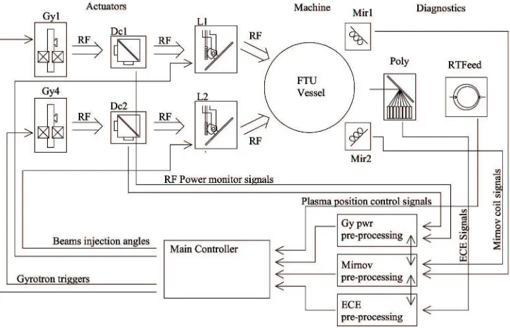
From the point of view of the control engineer, instabilities control in a tokamak machine doesn’t differ much from other control systems. Figure 1 summarizes the logical block of the whole system, process
Fig. 1.Logical block scheme of the control system
data must be acquired, a control algorithm should be run upon them and present valued for the control variables should be produced and delivered to the actuators.
Presently, the proposed instabilities control system uses these process measures, also called diag-nostics:
2. Signals from eight Mirnov coils of the machine (Mir1 and 2 in figure 1). These signals will be fed to Mirnov processing block. Sampling rate and acquisition chain for this subsystem is under development.
3. Two directional couplers on the two waveguide (Dc1 and Dc2 in figure 1). These couplers provide the control system with two synchronous measurements of the power delivered by the gyrotrons to the two symmetric antennas of the new ECRH launcher. Presently these two signals and the polychromator signals are acquired together.
As said, these diagnostics are distributed on the whole plant; on FTU the polychromator is located 70 meters away from the EC launcher controller. We chose to place a processing unit in the polychromator location in order to acquire its analog signals as close as possible to the source and to transmit these channel to the main control unit digitally. In the first experiments we chose RTNet Ethernet stack to handle this data transmission (which, obviously must be done in hard real time) since it is quite easy to use under Linux/RTAI environment. We are considering to use reflective memory technology [4] in the future.
From the point of view of actuators, referring to figure 1, the control system acts on two plant gyrotron (Gy1 and Gy4 in the figure) which deliver EC RF power to the just installed EC fast launcher. This launcher (L1 and L2 in the figure) is a two line, fast steerable, front mirror injection device [5] capable of fast steering EC beam both in poloidal and toroidal directions. The control system provides references (both poloidal and toroidal) for the steerable mirrors of the device. Gyrotron are triggered with a TTL logic signal per device which enables high voltage on the valve. The high voltage cannot be enabled instantly so a fixed ramp of 2kV/µsis automatically applied after the TTL enable signal this poses a limit on the speed of RF power turning on, and eventually on the actuator response. The nominal minimum on time is 50µsbut, for safety reasons, the normal adopted on time is 200µs. The fast launcher, on the other hand, has been thoroughly characterized in terms of step response and maximum speed. The 1 degree step response shows that the settling time is about 10ms, its nominal maximum speed is 10ms/degand its control system cycle time is 1ms. For all these reasons we adopted 1 ms cycle time for the main controller loop. This is a not optimal choice for the gyrotron trigger signal generation (which could be generated faster), but quite good for launcher references generation and available processing time.
From the hardware point of view during the first experimental implementation of this control sys-tem we had only two VME based industrial PCs. So we decided, as said before, to dedicate one of these to polychromator signal handling and the other was used to both RTFeed block [6] and main controller block of figure 1. The two machine were interconnected with a RTNet link. In the next fu-ture a further machine, a CompactPCI based industrial PC with last generation CPU (Intel i7 quad-core hyperthreading 2.1GHz CPU) which will handle the main controller tasks freeing RTFeed machine of this. Data from polychromator will arrive to this machine through a RTNet or RFM link, while data from RTFeed will arrive through a RTNet link. We chose to adopt the MARTe framework on these machines MARTe framewok is an open source multi-platform multi-threaded real time framework ex-pressly developed to implement and deploy complex control systems. Among others benefits we found it to be of great help in these aspects:
1. Fine modularity. The control system can be easily split into a great number of subtasks and the association of them is quite transparent and easy. This allowed the integration of contribution of many people into a whole working control system.
2. Hardware and operating system abstraction. The framework tries to be unlinked with the particular hardware and operating system used, this simplify the initial development of the control system which can be done in a friendly environment, such as a plain Linux os, like we did.
3. Performance monitor. A basic but very functional performance monitor has been introduced into the framework which allows the performance measurement and the profiling of real time code at design time, allowing to split real time tasks among different machines.
3 Control loop GAMs description
In the MARTe framework the control loop blocks, seen as computational blocks which take data from one or more input interfaces and provide elaborated data to one or more output interfaces, are called GAMs (Generic Application Modules). These GAMs can be combined quickly to modify the control algorithm also during the experimental phase. In this work a number of these blocks have been written and tested, they are described in the following:
1. FTUDataLoadGAM. This GAM is for simulation purposes: it takes real data from a formatted file and gives them to the other requesting GAMs.
2. ECEPreprocessGAM. This GAM is used for calibrating ECE signals, it takes bare ECE signals from the polychromator ADCs and performs an offset evaluation and subtraction just and a scale factor to provide signals from the ADC value in physical units (eV here). Offsets are evaluated just before the beginning of the plasma shot and kept equal for the shot duration. Calibration coef-ficients must be manually provided to the GAM by Michelson interferometer and polychromator signal offline comparison.
3. ECEAutoCrossCorrelationGAM. This GAM performs a number of auto and cross correlations be-tween ECE signals and other plant signals. In particular it performs ECE-ECE auto and cross cor-relation which are useful for instabilities detection, ECE-gyrotron power cross corcor-relation which gives, under certain working conditions, the deposition location of EC power and finally ECE-Mirnov cross correlation, which again are helpful as instability markers. [7]
4. RPolychromatorGAM. This GAM computes from the machine toroidal current measure and poly-chromator grating orientation the spatial position of the polypoly-chromator channels in the machine. The computation takes into account corrections of magnetic field ripple caused by machine poloidal coils.
5. ECEGyRdepGAM. From output of the two previous GAMs this block computes the actual depo-sition point of EC power on the machine major axis.
6. EquifastRaytraceGAM. This is a quite complex GAM. It receives input from almost all others GAMs and need some experiment data also from RTFeed machine. It is able to quickly provide an equilibrium reconstruction of the plasma in the machine (in term of equiflux surfaces). The equilibrium is evaluated by interpolation on pre-registered machine equilibria starting from some real machine measurements, so it comes from a statistical analysis. Even though this is not the most accurate manner to evaluate the equilibrium, it is a very fast way and so very suitable for our purposes. Besides this, the GAM has a EC beam raytracing engine which can compute the real wave path of teh EC wave in plasma starting from launch angles. Wave propagation is computed taking into account real plasma density measurement and the raytraced power deposition point is evaluated.
7. MirnovSVDGAM. This GAM perform a SVD (single value decomposition) algorithm on a matrix composed of Mirnov channel samples. The decomposition is able to give an estimate of n and/or m periodicity of a possible instability and some instability markers
8. ECRHLauncherControlGAM. This is the main control GAM, it must receive outputs from all others control GAMs and provide references for actuators. Its present behavior will be discussed better in next section.
As seen we have implemented a suite of control blocks into MARTe framework in order to have all foreseen elements to build a ECRH instabilities control loop once in experimental session. Next session will show an example of control loop testing.
4 R-pointing open loop example
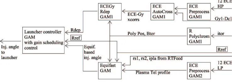
Fig. 2.GAM block interconnection for R pointing experiment
passed ECE are first preprocessed by one instance of the ECEPreprocessGAM which subtract the initial offset and convert them into physical units. Then the ECEAutoCrossCorrelationGAM1 cross correlates the high-passed ECE channels with the power signal measured by the directional coupler on the waveguide. The crosscorrelation results are fed to the ECEGyRdepGAM1 which computes the experimental power deposition point, Rdep. Note that we are assuming a modulated power coming from gyrotron, see [7]. RPolychromatorGAM takes the measurement of toroidal coils current and evaluates the corresponding value of toroidal magnetic field (at a given conventional radius) and the position of polychromator channels in the plasma, data which are necessary to ECEGyRdepGAM and EquifastGAM. EquifastGAM, taking engineered slow polychromator data from a second histance of ECEPreprocessGAM and other plasma runtime data from RTFeed computes a runtime equilibrium. Having the equilibrium and knowing the resonance (absorption) radial position, EquifastGAM is also able to compute an injection angle (geometric or raytraced, here we consider only the former) to reach the desired reference radius Rref.
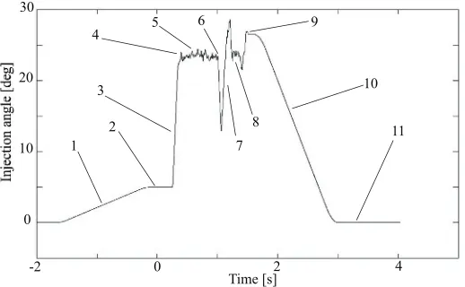
Equifast-based injection angle and deposition radius based on ECE-Gy crosscorrelation are fed to the final GAM, the launcher controller GAM. This GAM is responsible of the whole experiment outcome. Its behavior is articulated in phases and it can be better understood analyzing its output, the launcher injection angle itself. An example is presented, for FTU shot no. 34905 with Rref equal to 1.012 m, in figure 3. To understand the output it should be noted that shot no. 34905 was a launcher test shot in which the launcher performed apreprogrammed poloidal scanwith modulated gyrotron power. So we are analyzing anopen loop outputwith plasma data coming from a poloidal scan with modulated EC power. In figure plasma starts (in simulation) att=0s. Phases of the launcher position reference explained as follows:
1. Approach phase: the launcher steering mirror is brought to a preprogrammed guess position for a guess injection angle.
2. Idle phase: the launcher is kept in guess position in plasma startup phases in order to let all control block to stabilize.
3. Control engaged: the launcher is moved to the equifast-based injection angle (which is not equal to the guess angle) at its fastest speed. In this case the control GAM limits the reference speed to be equal to the designed maximum.
4. Equifast-based injection angle reached. 5. Equifast-based injection angle tracking.
6. Gyrotron modulated power turns on: at this point we have gyrotron power into plasma, so the Rdep algorithm can compute Rdep in a reliable manner.For this experimentwe superimpose a correction on the equifast-based injection angle proportional to the error Rref - Rdep in order to (once loop is closed on real plasma) make Rdep to follow Rref.
Fig. 3.Upper beam poloidal injection angle computed by the described system
8. Gyrotron modulated power turns off: launcher controller returns to purely equifast-based injection angle.
9. Control disengaged: the final position is kept until plasma is over. 10. Home phase: launcher is brought to home position.
As one can see, a whole experiment has been simulated and is ready to be tested on a real FTU plasma.
5 Conclusions
In this paper, the specifications of the control system for the tracking of MHD instabilities and their suppression with ECRH waves are given and the possible ways for its implementation have been explained, starting from a high-level view of the system and introducing the main design issues en-countered during the control algorithm synthesis.
An example of an open-loop power deposition tracking starting from real FTU data has been presented. The system is ready to be tested in the next experimental campaign of FTU.
References
1. A.Bruschi, W.Bin, S.Cirant, G.Granucci, S.Mantovani, A.Moro, S.Nowak, ”A new launcher for real-time ECRH experiments on FTU”, Fusion Science and Technology 55, N.1 (2009), pp.94-107. 2. Sozzi et al., this conference.
3. A.C. Neto, F. Sartori, F. Piccolo, R. Vitelli, G. De Tommasi, L. Zabeo, A. Barbalace, H. Fernandes, D.F. Valcarcel, and A.J.N. Batista. ”Marte: A multiplatform real-time framework” Nuclear Science, IEEE Transactions on, 57(2): 479-486, 2010.
4. http://www.ge-ip.com/products/family/reflective-memory
5. A. Moro, E. Alessi, G. Artaserse, W. Bin, L. Boncagni, A. Bruschi, S. Cirant, G. D’Antona, O. D’Arcangelo, D. Farina, R. Ferrero, L. Figini, C. Galperti, S. Garavaglia, G. Granucci, G. Grosso, V. Mellera, D. Minelli, V. Muzzini, A. Nardone, S. Nowak, G. Ramogida, A. Simonetto, C. Sozzi, ”In vessel characterization and first power tests on plasma of the Real-Time controllable EC launcher on FTU Tokamak”, this conference.
6. L. Boncagni, Y. Sadeghi, C. Centioli, S. Sinibaldi, V. Vitale, L. Zaccarian, G. Zamborlini Progress in the migration towards the real time framework MARTe at the FTU tokamak 26th Symposium on Fusion Technology (SOFT) Porto (Portugal) September 27 - October 1, 2010