© 2017, IJCSMC All Rights Reserved 326 Available Online at www.ijcsmc.com
International Journal of Computer Science and Mobile Computing
A Monthly Journal of Computer Science and Information Technology
ISSN 2320–088X
IMPACT FACTOR: 6.017IJCSMC, Vol. 6, Issue. 4, April 2017, pg.326 – 331
Implement Intrusion Detection System
in Ad-hoc Wireless Network
Swapnil Warade
1, Prof. Shyam Dubey
21
Research Scholar, 2Associate Professor
Department of Computer Science, Nuva College of Engineering & Technology-Nagpur, INDIA
Abstract – In wireless sensor networks, the power resource of each sensor node is limited. Minimizing energy dissipation and maximizing network lifetime are important issue in the design of routing protocols for sensor networks. This paper proposes a new improved cluster algorithm of LEACH protocol which is intended to balance the energy consumption of the entire network and extend the lifetime of the network.
Keywords: Cluster Head, Hierarchical routing, Wireless Sensor Network.
I. INTRODUCTION
A Wireless Sensor Networks (WSN) form a subset of Ad-hoc networks . Wireless Sensor Networks have many restriction compared to Ad-hoc networks in terms of its sensor nodes capability of memory storage, processing and the available energy source. Wireless Sensor Networks are generally assumed to be energy restrained because sensor nodes operate with small capacity DC source or may be placed such that replacement of its energy source is not possible [1].
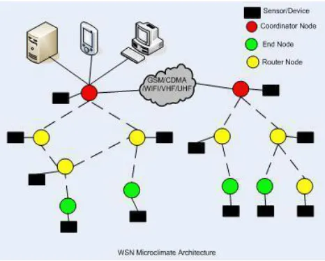
A wireless sensor network (WSN) consists of spatially distributed autonomous sensors to cooperatively monitor physical or environmental conditions, such as temperature, so und, vibration, pressure, motion or pollutant fig.1. They are now used in many industrial and civilian application area, including industrial process monitoring and control, machine health monitor environment and habitat monitoring, healthcare applications, home automation, and traffic control.
Fig. 1 Wireless Sensor Network
© 2017, IJCSMC All Rights Reserved 327
II. DESCRIPTION OF CURRENT LEACH PROTOCOL
LEACH protocol is a typically representation of hierarchical routing protocol. It is a self adaptive and self organised. Leach protocol uses round as unit ,each round is made up of cluster set-up stage and steady state storage for the purpose of reducing unnecessary energy costs[2] .
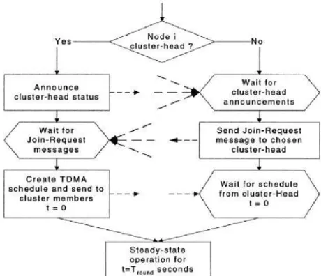
The steady-state phase duration is usually much longer than set-up phase duration. However, the first phase is more important, in which sensor nodes are allowed to elect themselves as cluster-heads randomly, and then divided into clusters. Each node that becomes the cluster head (CH) will create a TDMA schedule for the sensor nodes within the cluster. That allows the radio components of each non-CH-node to be turned off all times except during their transmit time. Fig. 2 shows the cluster formation algorithm of LEACH.
Fig. .2 Timeline Showing Operation of LEACH
Fig.3 Cluster Formation of LEACH Protocol
III.RELATED WORK ON LEACH PROTOCOL
The LEACH Network is made up of nodes, some of which are called cluster-heads .The job of the cluster-head is to collect data from their surrounding nodes and pass it on to the base station. LEACH is dynamic because the job of cluster-head rotates.
Cluster-heads can be chosen stochastically (randomly based) on this algorithm:
If n < T(n), then that node becomes a head . The algorithm is designed so that each node becomes a cluster-head at least once.
Cluster Head selection Algorithm
Pi(t) is the probability with which node I elects itself to be Cluster Head at the beginning of the round r+1 (which starts at time t) such that expected number of cluster-head nodes for this round is k.
(1)
© 2017, IJCSMC All Rights Reserved 328
Each node will be Cluster Head once in N/k rounds (Round #1,2,3 … Round #N/K, then Round #1, #2, …). – N/K also means cluster size. In each cluster, each sensor has equal chance to become CH.
Probability for each node I to be a cluster-head at time
(2)
Ci(t) = it determines whether node I has been a Cluster Head in current round cycle (Total: r rounds; every N/K rounds we form a “cycle”; In each cycle each node should become CH ONLY ONCE).
(3)
total no. of nodes eligible to be a cluster-head at time t This ensures energy at each node to be 2pprox.. equal after every N/k rounds.
Using (2) and (3), expected no of Cluster Heads per round is,
Cluster Formation Algorithm:
1. Cluster Heads broadcasts an advertisement message (ADV) using CSMA MAC protocol. ADV = node’s ID + distinguishable header.
2. Based on the received signal strength of ADV message, each non-Cluster Head node determines its Cluster Head for this round (random selection with obstacle).
3. Each non-Cluster Head transmits a join-request message (Join-REQ) back to its chosen Cluster Head using a CSMA MAC protocol.
Join-REQ = node’s ID + cluster-head ID + header.
4. Cluster Head node sets up a TDMA schedule for data transmission coordination within the cluster.
5. TDMA Schedule prevents collision among data messages and energy conservation in non cluster-head nodes.
IV. SIMULATIONSETUPANDSCENARIOS
With the nodes being deployed, some assumptions were made concerning the node features and these are as follows:
All nodes are homogeneous in nature; All nodes starts with the same initial energy;
The base station is situated at the centre of the area space; Clusters and nodes are static;
Normal nodes transmit directly to their respective cluster heads within a particular cluster; Cluster heads use multi-hop routing to relay data to the data sink;
The parameters used in the simulation are listed in Table 1 TABLE 1
The sensor nodes in the network are formed into clusters of different sizes of one, two, three, four and five. Tround = 0.08 seconds * (Estart / 9 mJ)
Estart : initial energy of the nodes.
Tround : time after which cluster-heads andassociated clusters should be rotated .
© 2017, IJCSMC All Rights Reserved 329 Fig. 4
Fig 4: Non Hierarchical formations of 100 nodes randomly tested in a geographical location of X and Y coordinates measured in meters
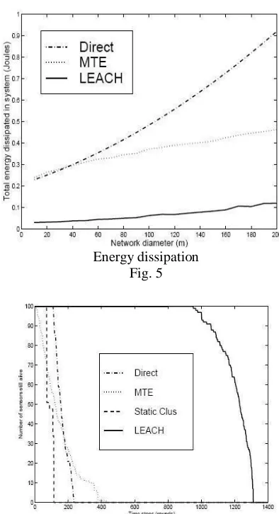
LEACH is able to distribute energy dissipation evenly throughout the sensors, doubling the useful system lifetime for the networks we simulated.
V. SIMULATIONRESULT
Energy dissipation Fig. 5
© 2017, IJCSMC All Rights Reserved 330 Fig. 7
Live nodes (circled) Show the live network node. Dead nodes (dotted) show the dead node in the network.
Total amount of data received at the BS over time. Fig 8
Fig. 9
The cluster head(s) of m-th cluster formed aggregates the data received from other sensor nodes with its own data and transmits it to the next hop cluster head closer to the base station or to the base station depending on the cluster formation and the shortest distance between the cluster head and the BS. At every transmission or reception made, energy reduction occurs for every node, thereby cluster head rotation was utilized to help prolong the lifetime of the WSN.
© 2017, IJCSMC All Rights Reserved 331
VI. CONCLUSION
It is proved that the proposed clustered routing technique offers when compared to the non-clustered routing. We investigated the advantage of the proposed technique by comparing the time in which the first node dies during the 100 rounds of simulation (network lifetime) to that of the non-hierarchical routing technique.
REFERENCES
[1] W. Heinzelman, “Application-specific protocol architectures for wireless networks,” Ph.D. dissertstion, Mass. Inst. Technol., Cambridge, 2000.
[2] Gowrishankar , S. , Basavaraju,T.G, Manjaiah , Handy. M. J, Haase. M, Timmermann. D. Low Energy Adaptive Clustering Hierarchy with Deterministic Cluster-Head Selection. IEEE International Conference on Mobile and Wireless Communications Networks, 2002, Stockholm.
[3] Yrjölä Juhana. Summary of Energy-Efficient Communication Protocol for Wireless Microsensor Networks, 13th March 2005.