AZR-LEACH: An Energy Efficient Routing Protocol
for Wireless Sensor Networks
Zahoor A. Khan, Srinivas Sampalli
Faculty of Computer Science, Dalhousie University, Halifax, Canada Email: [email protected]
Received September 3, 2012; revised October 8, 2012; accepted October 18, 2012
ABSTRACT
Reducing the energy consumption of available resources is still a problem to be solved in Wireless Sensor Networks (WSNs). Many types of existing routing protocols are developed to save power consumption. In these protocols, clus- ter-based routing protocols are found to be more energy efficient. A cluster head is selected to aggregate the data re- ceived from root nodes and forwards these data to the base station in cluster-based routing. The selection of cluster heads should be efficient to save energy. In our proposed protocol, we use static clustering for the efficient selection of cluster heads. The proposed routing protocol works efficiently in large as well as small areas. For an optimal number of cluster head selection we divide a large sensor field into rectangular clusters. Then these rectangular clusters are further grouped into zones for efficient communication between cluster heads and a base station. We perform MATLAB simu- lations to observe the network stability, throughput, energy consumption, network lifetime and the number of cluster heads. Our proposed routing protocol outperforms in large areas in comparison with the LEACH, MH-LEACH, and SEP routing protocols.
Keywords: Routing Protocol; Wireless Sensor Networks; LEACH; AZR LEACH
1. Introduction
In recent years, researchers have been attracted by Wire- less Sensor Networks (WSNs) due to their potential use in a wide variety of applications. A WSN contains dif- ferent types of autonomous sensor nodes that are used to sense and transfer the data wirelessly to the Base Station (BS) or the next receiver node. Typically hundreds or thousands of low cost sensors are used in WSNs [1]. Routing is an issue for these sensor nodes where the re- sources are limited. These wireless sensor nodes have limited energy, processing capabilities, and sensing abili- ties. Initially WSNs were used only in the battlefields for military purposes but now their use is extended for moni- toring and controlling the different processes in many other civilian areas. A wide range of sensors are avail- able to monitor the different ambient conditions such as temperature, pressure, humidity, movement, and lighten- ing conditions [2]. In a healthcare system, the implant and wearable sensors connected with a human body send the data to the coordinator node, which transfer these data towards the communication tier 2 devices. The tier 2 devices then route these data to the central database server for further processing [3]. The sensed information and aggregated data delivery is necessary for efficient communication between sensor nodes.
The information is routed from the root node to the BS
either directly or through other sensor nodes. The BS is either a fixed or a mobile node which is capable of con- necting the network to the internet where user can access and process the data. Routing in WSN is very challeng-ing due to the inherent characteristics that distchalleng-inguish this network from other wireless networks or cellular net- works. The most important constraint on WSN is the lim- ited battery power or sensor nodes. The required lower energy consumption restricts the sensor to use the limited resources such as less memory capacity, low transmit power, and less processing computations.
works. Our proposed algorithm aims to provide a higher throughput, a fewer number of dead nodes, and overall lower energy consumption compared to other protocols.
The remaining part of the paper is organized as fol- lows. Related work is discussed in Section 2. The pro- posed Routing protocol is presented in Sections 3. Per- formance evaluation for throughput, network stability and cluster head selection are discussed in Section 4. Fi- nally the conclusion is given in Section 5.
2. Related Work
Many routing protocols have been proposed for WSNs in the last few years. Main aim of these routing protocols is to reduce the energy consumption due to long haul trans- mission by arrangement of these scattered nodes into dif- ferent small areas which is referred to as clusters. In clus- tering method, sensor nodes of network organize them- selves in hierarchical structures. In a cluster, data collec- tion and aggregation are performed by cluster head in order to reduce the amount of energy consume by nodes to transmit data at long distance to the base station. Clus- ter head selection is usually based on probability. Non cluster head nodes select their cluster head on the basis of RSSI. Non-cluster head nodes then transmit their data to their cluster head. The role of cluster head is to data collect from non-cluster head nodes, aggregates and for- wards this data and its own data to the Base Station. One of the first hierarchical routing protocols in WSNs is Low Energy Adaptive Clustering Hierarchy (LEACH) [7]. In LEACH [7] protocol, the dynamic clustering mechanism is adopted in which a node elects itself to become a cluster head by some probability and broad- casts its status to the entire network. All the nodes are assumed to be homogeneous in terms of their energy. A cluster head consumes more energy than a non-cluster head node as the cluster head receives data from all clus- ter member nodes and then transmits their data to the base station directly by using single hop communication. Each node in the network has a chance to become a clus- ter head during network lifetime. A greater number of nodes may elect themselves as cluster heads than the desired number of cluster heads. This increased number may cause huge energy consumption due to performing the additional functions. The main drawbacks of LEACH protocol are uneven distribution of cluster heads, high transmission power required in the case of large areas, and lower stability region due to the early death of its nodes. To overcome these drawbacks LEACHCentral- ized (LEACH-C) [10], Multi-Hop LEACH (MH-LEACH) [11], and Stable Election Protocol (SEP) [12] provide the methods to solve uneven distribution of cluster heads, single hop communication, and lower stability respec- tively.
LEACH-C [10] uses a centralized cluster head selec- tion mechanism in which cluster heads are selected by the base station. In each round, the base station receives the current location and remaining energy information from all nodes in the network. Using the remaining en- ergy information, the base station determines a set of nodes for the cluster head selection. The base station computes the average node energy of the network. If the remaining energy of a node is greater or equal to the av- erage node energy, the node will be selected in the can- didate set for the cluster head. After determining the can- didate set, the base station finds the optimal number of cluster heads and clusters by using an approximation algorithm such as simulated annealing [9]. The simulated annealing algorithm runs on the candidate cluster head set to find the best cluster head node and clusters. Once the optimal cluster head and clusters are determined, the base station broadcasts the cluster heads IDs, cluster member node IDs, and transmission schedule for each cluster to all nodes in the network. Each node compares its ID with the cluster head ID, and if it matches, then it acts as the cluster head. Otherwise the node determines its slot in the transmission schedule and transmits data to the cluster head in its slot. One of the main drawbacks in LEACH-C [10] is repeated cluster formation overhead. There is also information and energy wastage because of fixed round time.
MH-LEACH [11] selects an efficient path from the cluster head to the base station. The sensor nodes send the data to their cluster head. The cluster head then ag- gregates the data and forwards it to the base station. Unlike LEACH which uses a single hop communication, MH-LEACH sends the data from the cluster head to an- other one, if available, closer to the base station. That cluster head forwards the data to the base station. The benefit of MH-LEACH is to save the transmission power for cluster heads that are farther away. However, the bat-tery of cluster head closer to the base station runs out due to forwarding the data from all farther cluster heads.
SEP [12] introduces the concept of advanced nodes. The advanced nodes are equipped with higher energy resources. SEP uses the weighted elected probabilities for normal nodes to select advanced nodes as well as normal nodes for cluster heads. The method used in SEP increases the stability region but reduces the network lifetime and throughput.
In order to overcome the drawbacks of LEACH, LEACH-C, MH-LEACH, and SEP; we proposed a new routing protocol AZR-LEACH which is discussed in next section.
3. Advanced Zonal Rectangular LEACH
(AZR-LEACH) protocol is based on LEACH protocol. In order to overcome the shortcomings of LEACH [7], LEACH-C [10], MH-LEACH [11], and SEP [12] proto- cols, a static clustering technique is used to optimize cluster head selection in our enhanced protocol. The logi- cal partitions of sensor deployment area into rectangular clusters, advanced clusters, and zones help to improve the efficient communication between cluster heads and the base station.
3.1. Architecture
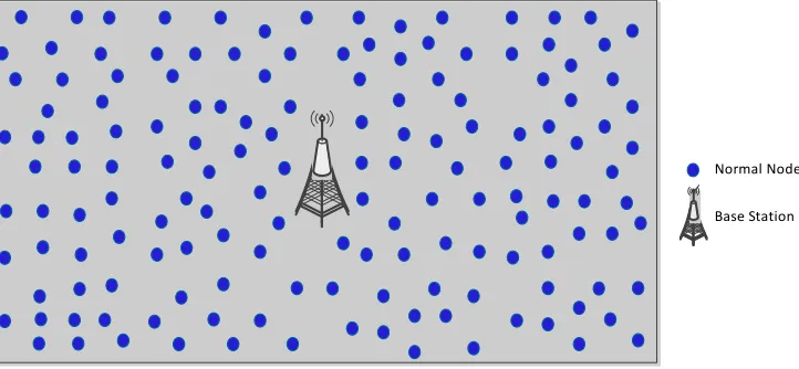
The basic architecture of Wireless Sensor Networks used in our protocol is shown in Figure 1.
We assume that the sensor nodes are deployed ran- domly and uniformly, are not movable, and are homoge- nous initially with respect to their antenna gain. It is also assumed that the dimensions of the sensor field are given and the coordinates of the base station are known. The base station is capable of receiving, aggregating, and then forwarding the data from the cluster heads to the desired destinations.
3.2. Procedure
The LEACH protocol uses dynamic clustering technique. The proposed AZR-LEACH protocol opts for static clus- tering. The working procedure of AZR-LEACH is very simple. It is a round based protocol like LEACH, and every round consists of two phases: setup phase and steady state phase. Unlike LEACH, our proposed proto- col introduces three additional concepts which are logical formations of rectangular clusters, selection of advanced clusters, and a combined group of rectangular clusters to form zones. The details of these additional concepts and phases used in AZR-LEACH are discussed below.
3.2.1. Rectangular Clusters
The entire network is divided into fixed rectangular clus-
ters. These rectangular clusters are heterogeneous; that is each cluster may have a different number of nodes. Usu- ally the base station is placed in the canter of the deploy- ment area. The formation of rectangular clusters requires the dimensions of the deployment area. As mentioned earlier, it is assumed that the dimensions of the deploy- ment area and position of the base station is known. The subdivision of sensor area starts from the center and the area covered by each rectangular cluster is the same. For example if the total area is 500 m × 500 m and the base station is in the canter then 16 rectangular clusters with area 125 m × 125 m each will be formed as shown in Figure 2.
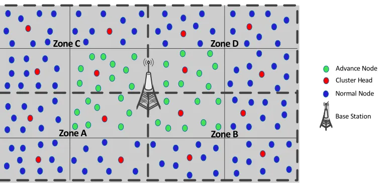
3.2.2. Selection of Advanced Clusters
The clusters which are directly connected to the base sta- tion are selected as advanced clusters and the nodes in those clusters are known as advanced nodes. The ad- vanced nodes are shown in Figure 3 in green. An ad- vanced cluster head is capable of receiving the data from its own cluster member nodes as well as the other cluster heads and forwarding it to the base station. The use of advanced clusters and nodes helps to provide an energy- efficient support of Multi-Hop communication. The ad- vanced cluster heads use lower transmission power than other cluster heads due to their closest location to the base station. Generally the base station is placed in an accessible location so the advanced nodes have easier access to it. The advanced nodes are also equipped with higher energy resources. In our experiments, we used 1.5 times more energy than the other nodes. Like SEP [12], using more energy in the advanced nodes helps to in- crease the stability region.
3.2.3. Formation of Zones
The group of rectangular clusters forms a zone. Each zone must contain at least one advanced cluster. The dot- ted lines in Figure 4 show the boundaries of the zones.
Normal Node
[image:3.595.120.481.554.721.2]Base Station
Normal Node
Base Station
0 125m 250m 375m 500m
125m 250m 375m
500m0 125m 250m 375m 500m
125m 250m 375m 500m
0 0
Figure 2. Rectangular clusters formation.
Normal Node Base Station
0 125m 250m 375m 500m
125m 250m 375m
500m0 125m 250m 375m 500m
125m 250m 375m 500m
0 0
Advance Node
Figure 3. Advanced clusters and nodes.
Normal Node
Base Station
0 125m 250m 375m 500m
125m 250m 375m
500m0 125m 250m 375m 500m
125m 250m 375m 500m
0 0
Advance Node
Zone A
Zone B
[image:4.595.104.490.78.727.2]Zone C Zone D
Figure 4. Formation of zones.
T n
T nThe advanced cluster nodes participate in the selection of the advanced cluster head by using the same method as followed by other clusters. The idea of zone is to man-age and balance the network traffic coming from the far-ther cluster nodes. The cluster heads from ofar-ther zonal areas send their traffic to the cluster head of the advanced cluster which forwards it to the base station. The ad- vanced cluster head communicates with only those clus- ter heads that belong to its zone.
cluster heads, so there will be an inappropriate cluster head selection. Unlike LEACH [7], our proposed proto- col follows a different approach for cluster head selection. From each rectangular cluster, the node with the highest remaining energy will be selected as the cluster head. The current cluster head will decide the next cluster head for the next round in its cluster. All the nodes send their remaining energy information along with data packets to the cluster head. From this information, the current clus- ter head elects the node with the highest remaining en- ergy as the cluster head for the next round. The rotation of CHs can be seen in Figures 5 and 6. After every round, a different CH is chosen. Every node will become a CH after 1/p rounds.
In short, the nodes in a cluster can send the data only to their cluster head, and that cluster head can only send the data to the advanced cluster head of its own zone.
3.2.4. Setup Phase
In the setup phase, every node decides to become a clus-ter head or not. In LEACH [7] protocol, each node elects itself as a cluster head on the basis of the desired per- centage of the cluster heads for the network and number of times a node has been a cluster head. Each node chooses a random number from zero to one and then cal- culates the threshold . The node then compares the random number with T n . If the random number is less than or equal to , the node becomes a cluster head for the current round. The threshold for cluster head selection is calculated by using Equation (1).
Using CSMA/CA protocol, the new cluster heads broadcast their status in their intra cluster range. Because the network is divided into fixed rectangular clusters, cluster heads do not have to broadcast their status to the whole network. Remaining non-cluster head nodes, which receive a broadcast message from the cluster head in their rectangular cluster, transmit a response message back to the cluster head in their rectangular cluster. The cluster head assigns TDMA slots to each node in its cluster and broadcasts this TDMA schedule to all the nodes.
if
Otherwise nA 1
1 * mod
0 d d d P P r T n P
(1) 3.2.5. Steady State Phase After cluster heads selection and TDMA slots allocation,
the steady state phase starts. The steady state phase of AZR-LEACH is almost similar to LEACH. Based on TDMA protocol, the communication starts between the cluster head and their respective CHs in their allocated time slots. The cluster node can only communicate with its respective CH in a predefined time slot. All cluster nodes remain in sleep mode during unallocated time slots. This leads to better energy efficiency of the protocol. where Pd is the desired percentage of cluster heads, A is
the group of nodes which are not selected as cluster heads in previous 1/p rounds and r is the current round. After several rounds, the energy of nodes in the network will become uneven, and nodes with high energy and low energy will have the same probability of becoming the
Normal Node
Base Station Cluster Head
Zone C Zone D
Zone A Zone B
[image:5.595.111.490.536.722.2]Advance Node
Zone C Zone D
Zone A Zone B
Normal Node
[image:6.595.114.483.79.266.2]Base Station Cluster Head Advance Node
Figure 6. Rotation of cluster heads in AZR-LEACH.
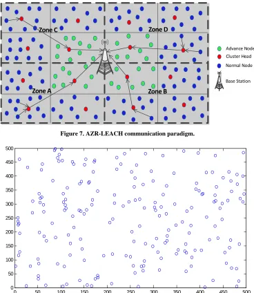
Non-cluster head nodes transmit their data to their as- sociated cluster head in their rectangular cluster which aggregates the data of all non-cluster head nodes. Then this cluster head forwards the aggregated data to the ad- vance cluster head node of its zone, which is directly connected to the base station. The advance cluster head node aggregates and compresses all data received from its zone cluster head nodes in addition to the non-cluster head nodes of the advanced cluster. After receiving all of the data, the advance cluster head node forwards this ag- gregated data to the base station as depicted in Figure 7.
3.3. Advantages
The main advantages of AZR-LEACH over LEACH, LEACH-C, MH-LEACH, and SEP protocols are given below.
Simple Implementation: The implementation of AZR- LEACH is very simple. Like LEACH, the cluster forma- tion process is not required in the setup phase of every round.
Static rectangular clusters: The static rectangular cluster formation proves to be more energy efficient than dynamic cluster formation. In dynamic cluster formation, the clusters are formed in the setup phase of every round which causes more energy consumption.
Balanced Cluster Head: Each rectangular cluster contains one cluster head. The number of cluster heads, like the number of rectangular clusters, is fixed through- out the simulation until a complete cluster is dead.
Equally distributed network: The division of whole deployment area in equally distributed sub-areas helps to balance the network traffic.
Energy efficient: By dividing the network in rectan- gular clusters and zones reduces the traffic load. All nodes from a cluster send data to their own cluster head, and the cluster heads in a zone transfer that data to the advance cluster head. The multi-hop communication due
to advanced cluster head nodes reduces the energy con- sumption.
4. Performance Evaluations
Extensive simulations have been conducted by using the MATLAB simulation environment to compare the per- formance of our proposed Advanced Zonal Rectangular- LEACH (AZR-LEACH) protocol with the Low Energy Adaptive Clustering Hierarchy (LEACH), Multi-Hop LEACH (MH-LEACH), and Stable Election Protocol (SEP). The results show that the AZR-LEACH extends the network lifetime, increases the overall throughput, reduces the energy consumption, and optimizes the num- ber of cluster heads. In this section, simulation parame- ters used for our experiments are given in Section 4.1. The simulation results are discussed in Section 4.2.
4.1. Simulation Parameters
The nodes are randomly deployed within the area of 500 m × 500 m. The base station is located at the center of the deployment area with coordinates 250 m × 250 m. The population of nodes for this simulation is 200 (i.e. n = 200). A sample of randomly deployed nodes for our experiments is shown in Figure 8. The different samples of randomly deployed nodes are used for each simulation and the results discussed in the next sections are the av- erage values of 30 simulations.
We simulate LEACH [7], MH-LEACH [11], SEP [12], and AZR-LEACH protocols by using the parameters defined in Table 1.
The following terms are used to evaluate the perform- ance of clustering protocols [12]:
Stability Period: The time interval between the start of the network operation and the death of the first sensor node is called stability period or stable region.
Normal Node
Base Station Cluster Head
Zone C Zone D
Zone A Zone B
[image:7.595.113.481.84.508.2]Advance Node
Figure 7. AZR-LEACH communication paradigm.
0 50 100 150 200 250 300 350 400 450 500
0 50 100 150 200 250 300 350 400 450 500
[image:7.595.117.483.84.270.2]Figure 8. Random deployment of nodes.
Table 1. Simulation parameters.
Parameters Values Network size 500 m × 500 m
Initial energy 500 mJ
Pd 100 mJ
Data aggregation energy cost 50 pj/bit j Number of nodes 200
Packet size 4000 bit Transmitter electronics 50 nJ/bit Receiver electronics 50 nJ/bit Transmit amplifier 100 pJ/bit/m2
interval between the death of first node and the death of the last sensor node.
Network Lifetime: The time interval between the start of the network operation and the death of the last sensor node is called network lifetime.
Number of Cluster Heads per round: The total number of nodes selected as cluster heads from the whole network in each round. These cluster heads are response- ble to receive the data from member nodes and then send these data, after aggregation, to the sink.
Number of Alive Nodes: The total number of sensor nodes that have not yet depleted all of their energy.
Number of Dead Nodes: The total number of sensor nodes that have consumed all of their energy and are not able to do any kind of functionality.
[image:7.595.58.286.555.733.2]heads to the sink is called the throughput. The rate of data sent from member nodes to their respective cluster heads is also called throughput.
Reliability: It depends upon the measurement of the stable region and the unstable region. The larger stable region and smaller unstable region means better reliabil- ity.
There is a trade-off between reliability and network lifetime. Network lifetime includes both stable and un- stable regions. For the same stable region, a smaller un- stable region means more reliability but a shorter net- work lifetime.
4.2. Simulation Results
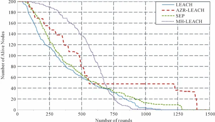
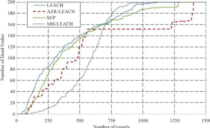
[image:8.595.113.482.507.717.2]MATLAB tool is used to get the simulation results. As mentioned earlier, AZR-LEACH works in rounds. The total number of rounds used for our experiments is 1500. Simulations of AZR-LEACH in comparison with LEACH [7], MH-LEACH [11], and SEP [12] are performed to observe the frequency of dead and alive nodes per round, number of Cluster Head (CH) nodes per round, network lifetime, and overall throughput.
Figure 9 shows that AZR-LEACH has greater stability time as compared to LEACH [7] and SEP [12] but lower stability time than the MH-LEACH [11]. The first node of AZR-LEACH is dead after approximately 80 rounds whereas the first node of LEACH, MH-LEACH, and SEP is dead after approximately 39, 107, and 62 rounds respectively. By considering the total 1500 rounds, the stability period of LEACH, MH-LEACH, SEP, and AZR-LEACH are 2.6%, 7.1%, 4.13%, and 5.33% re- spectively. The MH-LEACH provides the better stability time but its overall network lifetime shown in Figure 10
is shorter than our protocol.
The last node of LEACH [7], MH-LEACH [11], SEP [12], and AZR-LEACH is dead after approximately 1079, 1113, 1284, and 1401 rounds respectively. The network lifetime of AZR-LEACH is 23%, 20.56%, and 8.35% greater than LEACH, MH-LEACH, and SEP respec- tively as depicted in Figure 10.
Figure 11 shows that throughput of AZR-LEACH is significantly greater as compared to LEACH [7], MH- LEACH [11], and SEP [12] in stable and unstable re- gions. From this graph we see that AZR-LEACH guar- antees about 23.39%, 31.51%, and 47.42% more packets to the base station in comparison with LEACH [7], MH- LEACH [11], and SEP [12] respectively. The throughput of AZR-LEACH is more than the other three protocols because of static clustering and the efficient number of cluster head selection. Thus, it proves that AZR-LEACH has higher throughput as compared to LEACH, MH- LEACH, and SEP.
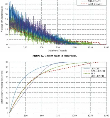
AZR-LEACH has an efficient number of cluster heads due to static clustering. LEACH [7], MH-LEACH [11], and SEP [12] select the number of cluster heads using distributed algorithms whereas a fixed number of cluster heads is selected during each round in AZR-LEACH. There is uncertainty in the selection of cluster heads in LEACH, MH-LEACH, and SEP. The numbers of cluster heads selected in each round by using these protocols are shown in Figure 12.
A lower number of selected cluster heads means each cluster head needs to forward more member nodes data, which results in the early depletion of the cluster head battery.
After becoming a cluster head, the node needs to per-form the additional functions of cluster heads. A higher
Figure 10. Total number of dead nodes in each round.
Figure 11. Comparative throughput.
number of cluster heads causes more network energy consumption.
Figure 13 shows the energy consumption comparison of LEACH [7], MH-LEACH [11], SEP [12], and AZR- LEACH.
The AZR-LEACH protocol reaches the threshold level of 100 joules in 1400 rounds, while LEACH, MH- LEACH, and SEP consumes 100 joules of energy in 1078, 1112, and 1282 rounds respectively. This shows that our proposed protocol is about 23%, 20.57%, and 8.42% better in energy consumption than LEACH, MH-
LEACH, and SEP respectively.
5. Conclusion
Figure 12. Cluster heads in each round.
Figure 13. Network energy consumption per round.
strategy, the stability period of network and network life- time have been optimized. Simulation results show that there is significant improvement in all these parameters when compared with existing routing protocols LEACH, MH-LEACH, and SEP.
REFERENCES
[1] J. Yick, B. Mukherjee and D. Ghosal, “Wireless Sensor Network Survey,” Computer Networks,Vol. 52, No. 12, 2008, pp. 2292-2330. doi:10.1016/j.comnet.2008.04.002
[2] I. F. Akyildiz, W. Su, Y. Sankarasubramaniam and E. Cayirci, “A Survey on Sensor Networks,” IEEE Commu-nications Magazine,Vol. 40, No. 8, 2002, pp. 102-114. doi:10.1109/MCOM.2002.1024422
[3] Z. Khan, N. Aslam, S. Sivakumar and W. Phillips,
“En-ergy-Aware Peering Routing Protocol for Indoor Hospital Body Area Network Communication,” Procedia Com-puter Science,Vol. 10, 2012, pp. 188-196.
doi:10.1016/j.procs.2012.06.027
[4] Y.-M. Lu and V. W. S. Wong, “An Energy-Efficient Mul-tipath Routing Protocol for Wireless Sensor Networks,” International Journal of Communication Systems,Vol. 20, No. 7, 2007, pp. 747-766. doi:10.1002/dac.843
[5] W. Heinzelman, J. Kulik and H. Balakrishnan, “Adaptive Protocols for Information Dissemination in Wireless Sensor Networks,” Proceedings of the 5th International Conference on Mobile Computing and Networking, Seat-tle, 15-19 August 1999.
Net-working, Boston, 6-11 August 2000.
[7] W. Heinzelman, A. Chandrakasan and H. Balakrishnan, “Energy-Efficient Routing Protocols for Wireless Mi-crosensor Networks,” Proceedings of 33rd Hawaii Inter-national Conference System Sciences, Maui, 4-7 January 2000. doi:10.1109/HICSS.2000.926982
[8] Y. Xu, J. Heidemann and D. Estrin, “Geography-In- formed Energy Conservation for Ad-Hoc Routing,” Pro-ceedings ACM/IEEE MobiCom’01, Rome, 16-21 July 2001.
[9] T. Murata and H. Ishibuchi, “Performance Evaluation of Genetic Algorithms for Flowshop Scheduling Problems,” Proceedings of 1st IEEE Conference Evolutionary Com-putation, Orlando, 27-29 June 1994.
[10] X. H. Wu and S. Wang, “Performance Comparison of LEACH and LEACHC Protocols by NS2,” Proceedings of 9th International Symposium on Distributed Comput-ing and Applications to Business, Engineering and Sci-ence, Hong Kong, 10-12 August 2010.
[11] R. V. Biradar, D. S. R. Sawant, D. R. R. Mudholkar and D. V. C. Patil, “Multi-Hop Routing In Self-Organizing Wireless Sensor Networks,” IJCSI International Journal of Computer Science,Vol. 8, No. 1, 2011, pp. 154-164.