Miniaturization of Compact Quadrifilar Helix Antennas for
Telemetry, Tracking and Command Applications
Alexandru Takacs1, 2, *, Herv´e Aubert1, 3, Daniel Belot4, and Hubert Diez4
Abstract—This paper addresses the miniaturization of Quadrifilar Helix Antennas (QHAs) for space applications (VHF Telemetry, Tracking and Command). Several shape miniaturization techniques were presented, and the impact of height reduction is quantified in terms of radiation pattern, gain and phase center. Simulated and experimental results demonstrate that Compact Quadrifilar Helix Antennas (CQHAs) with a height reduced up to 70% reported to the reference QHA can be designed. By using an appropriate optimization method, the impact of the miniaturization on CQHA performances in terms of radiation pattern and polarization purity can be minimized. Moreover, the impact on the gain is quantified, and design rules are reported. Finally a closed-form expression for estimating the gain of CQHAs from the height reduction factor is found.
1. INTRODUCTION
Quadrifilar Helical Antenna (QHA) is formed by four helical antennas wound around the same longitudinal axis [1]. Each helical antenna is rotated 90◦ with respect to one another. This 60-years old antenna is naturally convenient for radiating circularly-polarized waves with a large variety of radiation patterns and radiation modes. Compared with the (monofilar) helical antenna QHAs are a new class of antennas allowing better performances mainly in terms of maximum gain, (circular) polarization purity and phase center stability. Most of QHA designs require a ground plane perpendicular on the longitudinal axis of the helical antennas. The input ports can be located on the ground side (bottom side of the QHA) or at the opposite ends (top side of the QHA). Open-ended or short-circuited QHA can be designed if the unfed ends are open-ended or short-circuited. The input ports can be fed with equal amplitude, clockwise or counterclockwise, in phase quadrature with a phase progression of +90◦ (direct) or−90◦ (reverse) between two consecutive ports. Thus forward or backward wave can be generated by properly controlling the wounding sense of the helical antennas and the phase progression of the input signals.
QHAs are resonant structures, and the length of each constitutive helical antenna is multiple of the quarter wavelength. QHAs can be manufactured using wires or by using printed techniques. The wire is more suitable for low-frequency applications (VHF band) while the printed techniques are widely used for high-frequency applications (UHF or upper bands). The inherent properties of the QHAs (purity of the circular polarization, easy shaping of the radiation pattern and circularly-polarized radiated fields over a wide beamwidth) qualified QHA as an ideal candidate for satellite applications especially for Telemetry, Tracking and Command (TTC) applications. VHF QHAs are quite long antennas and, as other traditional antennas (e.g., parabolic antennas) QHAs face today to accommodation issues in the modern cost-effective satellite launch configuration. Consequently the miniaturization without significant degradation of radiation characteristics is the major challenge for any modern QHA design. QHAs are composed by four monofilar helical antennas.
Received 26 July 2015, Accepted 19 November 2015, Scheduled 16 December 2015
* Corresponding author: Alexandru Takacs ([email protected]).
1 CNRS, LAAS, 7 avenue du colonel Roche, F-31400, Toulouse, France. 2 Univ. de Toulouse, UPS, LAAS, F-31400, Toulouse,
The compact QHAs reported in this paper are planned to be used for a telemetry link in VHF band on board of the satellite Space-based Multi-band Variable Object Monitor (SVOM), a science satellite project developed in bilateral cooperation between the French Space Agency (CNES) and Chinese Space Agency. Several CQHA designs compatible with TTC requirements are presented here in order to analyze the impact of the miniaturization technique on antenna key parameters such as radiation patterns, antenna gain and phase center stability. Measurement results are reported for experimental validation purposes. The design of standard QHA is summarized in Section 2. The adopted miniaturization technique and CQHA design are presented in Section 3. The obtained experimental and simulated results of CQHAs are discussed in Section 4 with a focus on the impact of the miniaturization technique on the antenna gain.
2. QHA DESIGN
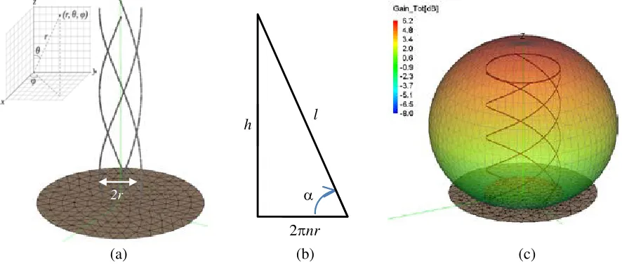
VHF QHAs are mainly used for low data rate telemetry link in the satellite communication systems. The key descriptors of QHA are the radius r of the helix (the radius of the supporting cylindrical structure), pitch angle α (or alternatively the number nof the turns can be used) and height h of the antenna (the height of the supporting cylindrical structure if it is used). The combination between the pitch angle, antenna height and antenna radius determines the antenna radiation characteristics. Fig. 1 shows a 3D simulation model of an open-ended QHA forn <1, the geometrical descriptors and relationship between n,α, r,h and l, where l denotes the total length of a single helical wire and, the simulated 3D radiation patterns (gain) of a short-circuited QHA. The length of the helical wire typically sets the resonant frequencies and is approximately an integer multiple of the quarter wavelength. λ/4 or 3λ/4 configurations are generally used for the open-ended QHA while λ/2 or λ configurations are often used for short-circuited QHA. Other key parameters impacting QHA design and performances are the diameterdg of the ground plane and the wire radius for wire-supported QHA (or the strip width for printed QHA). Wire-supported QHA designs were reported in [2–9] while printed QHA were studied in [10–15].
QHAs are mainly implemented on cylindrical surfaces (helical wires or strip lines are rolled up on cylindrical surfaces). However, QHAs can be conformed on conical [16], spherical [17] or square [18] surfaces.
Compact design is required for space application in order to fit the launch constraints. Thus
2r
h l
(a) (b) (c)
2πnr α
quarter/half wavelength configurations are preferred in spite of their well-known poor input matching (especially for the quarter wavelength design). The poor input matching can be compensated by the feeding network that operates, in most of cases, as a matching network. The feeding/matching network is not discussed in this paper.
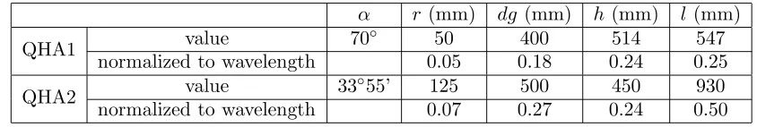
Two designs for TTC space applications, called here QHA1 and QHA2, were selected as reference QHAs. These antennas are planned to be used for a telemetry link in VHF band on board of the SVOM satellite [19]. QHA1 is an open-ended quarter-wavelength QHA designed for operating at 137 MHz while QHA2 is a short-ended half-wavelength QHA operating at 162 MHz. Both of them radiate circularly-polarized electromagnetic fields in the so-called axial mode (the maximum power is radiated along the positive Ozdirection). The main descriptors of these two reference QHAs are reported in Table 1.
Table 1. Geometrical descriptors of reference antennas QHA1 and QHA2.
α r (mm) dg (mm) h (mm) l(mm)
QHA1 value 70◦ 50 400 514 547
normalized to wavelength 0.05 0.18 0.24 0.25
QHA2 value 33◦55’ 125 500 450 930
normalized to wavelength 0.07 0.27 0.24 0.50
3. MINIATURIZATION TECHNIQUES AND CQHA DESIGN 3.1. Miniaturization Techniques
Several miniaturization techniques were proposed in order to implement CQHA. Those techniques can be classified as follows:
(i) shaping-based technique: the helical wires are shaped in order to reduce the axial height of the helix while keeping the total length of the wires almost unchanged and consequently, the operating frequency;
(ii) dielectric-loading technique: a dielectric with medium/high dielectric constant is used as a cylindrical support for the CQHA, and consequently, shorter wires (and smaller axial height) are used to operate at the desired frequency.
These two techniques can obviously be combined. The dielectric-loading technique facilitates the manufacturing process, but the radiation efficiency can be drastically degraded because of the dielectric loss. For this reason, the shaping-based technique is preferred here for miniaturizing the reference antennas QHA1 and QHA2 while keeping the radiation properties unchanged.
3.2. Quadrifilar Helix Antenna with Arbitrary Shape
In the past years, the shapes of constitutive wires in CQHAs were described by sinusoidal [6, 12, 15], periodic triangular [20], periodic trapezoidal [20], rectangular [12, 21], meandered [13, 14], pre-fractal [22], non-linear functions [23] and more recently, by the combination of pre-fractal and sine functions [24] (a review of the patents on CQHAs can be found in [25]). The axial height of the QHA can be also reduced by modifying the geometry/the shape at the center of the helical section [7, 8].
CQHA with an arbitrary wire shape can be modeled by the following system of parametric
equations: ⎧
⎨ ⎩
x(ti+1) =rcos (θi)
y(ti+1) =rsin(θi) i≥1
z(ti+1) =ti+1sin(α) +f(ti+1) cos(α)
, (1)
⎧ ⎪ ⎪ ⎪ ⎨ ⎪ ⎪ ⎪ ⎩ θi=
i−1
j=1
[g(tj+1)−g(tj)]
R =
g(ti)−g(t1)
R , i≥1
g(t) =tcos(α)−f(t) sin(α), t∈ , t∈[0, tmax]
wheretis a positive real number, tmaxthe solution of the equation h=z(tmax), andf(t) designates an
arbitrary function called the shaping function. Eq. (1) allows numerically computing each point of the CQHA as function of the angular coordinate θi. By choosing the real-valued numbersti it is possible to adjust the number of points that controls the shape of helical wires of CQHA. A standard Cartesian coordinate system is adopted here with the origin sets at the center of the ground plane. The first point (θi = 0◦) of the helical wire is positioned at x(0) =r, y(0) = 0 and z(0) = 0. A helical wire for QHA/CQHA is generated by using Eqs. (1) and (2). The three other constitutive helical wires of the QHA or CQHA are derived from a standard rotation over thez-axis with 90◦, 180◦ and 270◦ of the first helical wire. The shaping function of the reference QHA is given by:
f(t) =t (3)
while CQHAs with a sinusoidal profile (i.e., with wires mathematically described by a linear combination of nsine functions) are such that:
f(t) =
n−1
j=0
Ajsin (ωjt) (4)
where Aj et ωj denote the geometrical descriptors of the sinusoidal profile and can be viewed as amplitude and pulsation coefficients, respectively. Fractal shapes are generally not defined from closed-form expressions but are the result of an iterative process which can be further implemented inside most electromagnetic software. In order to obtain smaller structures the so-called modified fractal profiles (e.g., modified Von Koch or Peano) may be advantageously used. The procedure for modifying standard fractal shapes is detailed in [24] and [27]. These modified fractal profiles can be combined with a sine function as reported in [24] and [27] in so-called Sine-Modulated Modified Fractal (SMMF) profiles.
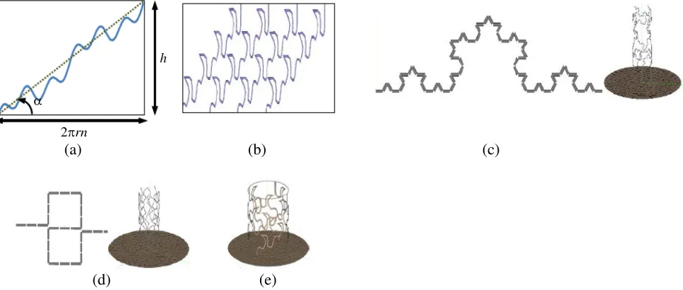
From a manufacturing point of view it can be convenient to print the shape of the helical wire (antenna) in a 2D plane and then to roll-up the printed 2D shape around a cylindrical supporting structure to form the CQHA. Fig. 2 illustrates 2D printed surfaces using various profiles and the corresponding 3D simulation models (FEKO) for CQHA. A periodicity is added into the design by
h
2πrn
α
(a) (b) (c)
(d) (e)
duplicating the elementary cell along each constitutive helical antenna. For example the cell appears twice in Fig. 2(a) while in Fig. 2(b) it is repeated four times. This periodicity (or number of cells) is an additional design parameter and is advantageously used during the optimization process.
3.3. Optimization Methodology
Miniaturizing QHA may impact the intrinsic antenna radiation performances. For TTC space applications it is mandatory to keep unchanged the radiation pattern and polarization purity. As the height of QHA becomes smaller, the antenna gain decreases. Depending on the application and overall power budget link lower gain can be increased by adding power amplifiers. However, the modification of the radiation pattern due to the antenna miniaturization cannot be easily compensated.
A good trade-off among compactness, directivity, input matching, antenna gain and efficiency can be obtained by using an adequate optimization methodology.
In order to find the best fitted CQHA, an optimization process has been implemented using the optimization module of FEKO software. The following objective (goal) functionGF has been defined in CADFEKO (OPTFEKO):
GF =w1·GF1+w2·GF2+w3·GF3+w4·GF4;
GF1 : S11<0.3
GF2 : LHC(D)>0 dB for −60◦ ≤θ≤60◦, ∀
GF3 : RHC(D)<−10 dB for −180◦ ≤θ≤180◦, ∀
GF4 : Gmax>0 dB
(5)
where w1, w2, w3 and w4 are weight coefficients (positive real numbers); LHC and RHC designate
respectively the left-handed and right-handed circular components of the directivity; S11 denotes the
magnitude of the reflection coefficient at each port of the CQHA;Gmaxis the maximum gain of CQHA.
The goal functionGF is computed at the desired operating frequency, that is, (i) at 137 MHz for QHA1 and CQHAs derived from QHA1 and, (ii) at 162 MHz for QHA2 and CQHAs derived from QHA2. The TTC technical specifications in VHF band require main polarization (LHC) of the reference QHA to be positive for−60◦ ≤θ≤60◦ while the cross-polarization (RHC) level is required to be lower than−10 dB for−180◦ ≤θ≤180◦. Consequently the goal functionGF intends to maintain the impedance matching (GF1), radiation pattern and polarization purity (GF2 and GF3) at the same level than the reference antenna. This allows facilitating the comparisons between radiation performances of optimized CQHAs and will force the best-fitted CQHAs to fulfill the typical technical requirements for TTC applications. In Eq. (5) a fourth goal is targeted for classifying the designed CQHA in terms of maximum gain criteria. For TTC application it is not convenient to use antennas with negative gain (in dBi) and consequently, Gmax > 0 dBi is required as an additional goal GF4. The optimization process uses the Grid Search
Method implemented in FEKO and is based on the methodology described in [6] and [26]. Thousands of CQHAs based on sinusoidal, standard or modified prefractal and, SMMF [24, 27] profiles were chosen for optimization purposes. The obtained results are summarized and discussed in the next section.
4. CQHA: RESULTS AND DISCUSSION
QHA1 CQHA1b CQHA1a
CQHA1c
CQHA1d CQHA1e
Figure 3. Manufactured wire-supported CQHAs derived from QHA1 using as shaping function various combinations of sine functions (CQHA1a, CQHA1b, CQHA1c and CQHA1d) and prefractal (Von Koch) profile combined with a sine function (CQHA1e).
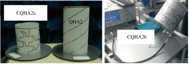
CQHA2b CQHA2a
QHA2
Figure 4. Manufactured printed CQHAs derived from QHA2 using a Von Koch-based SMMF as shaping function. CQHA2a was fabricated using the quasi-printed home-made technique on paper substrate while CQHA2b was manufactured using the commercially available technology from Inkjetflex.
Taking into account the dielectric supporting structure in the simulation model, the computational time increases significantly. For instance, the air-supported CQHA (i.e., without the cylindrical dielectric supporting structure) can be simulated in less than one minute on a PC with quad-core processor Intel Q9300 and 4GB of RAM, while the PVC-supported CQHA requires at least one hour. The computational time is a critical issue in the design/optimization process because thousands of CQHAs need to be computed here for finding the best-fitted CQHAs. In order to minimize the simulation time, the optimization was performed by using air-supported CQHA. Consequently, simulation and optimization results reported in this paper concern antennas without the cylindrical supporting structure. However, in order to predict the eventual impact of such a structure on antenna performances, electromagnetic simulations have been performed by taking into account this structure only for the optimized designs selected for the manufacturing. Adding dielectric (supporting tube or thin film) decreases more or less the operating frequency and degrades the antenna efficiency and gain. This effect is found to be critical for wire-supported CQHA using thick PVC tube and to be not significant for printed CQHA printed on thin dielectric film.
4.1. Measurement Technique
4.2. Simulation and Experimental Results
As previously explained, the wire-supported antennas (QHA1 and the CQHAs derived from QHA1) have been designed/optimized without taking into account the cylindrical PVC supporting structure. Consequently, the initial operating frequency was down-shifted from 137 MHz to approximately 120 MHz depending on the specific design. Five best-fitted wire-supported CQHAs were manufactured and characterized. Their characteristics are summarized in Table 2.
Table 2. QHA1/CQHA1 measured characteristics.
Antenna name
Height (mm)
Relative height (%)
Measured S11 (dB)
Measured directivity (dBi)
Shaping functionf(t)
QHA1 514 100 −6.2 at 123 MHz 5.9 Straight line
CQHA1a 270 52.5 −8.1 at 120 MHz 5.6 Sinusoidal
CQHA1b 217 42 −8.3 at 118 MHz 5.6 Sinusoidal
CQHA1c 193 37.5 −8.6 at 115 MHz 5.4 Sinusoidal
CQHA1d 135 26.2 −7.6 at 119 MHz 5.6 Sinusoidal
CQHA1e 167 32.5 −9.5 at 125 MHz 5.2 Von Koch SMMF
In order to compare the performances of overall manufactured antennas, the operating frequency of 120 MHz was selected for measuring the radiation patterns. The electromagnetic simulations indicate that the polarization purity and shape of the radiation pattern are not significantly modified compared with the reference antenna in a 10% bandwidth centered at the resonant frequency. Table 2 experimentally demonstrates that CQHAs with a height reduced up to 70% reported to the reference QHA can be designed.
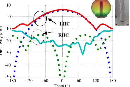
Figure 5 shows the measured and simulated LHC and RHC components of the directivity for the reference QHA1 at 120 MHz. These results demonstrate that TTC requirements given by Eq. (5) regarding the radiation pattern and the polarization purity are fulfilled by QHA1. As expected, the maximum directivity (5.9 dBi) was measured for Φ =θ= 0◦.
LHC
RHC
-180 -120 -60 0 60 120 180
Theta ( )o
10
0
-10
-20
-30
-40
-50
Directivity (dBi)
Figure 5. Experimental (continuous line) and simulated using FEKO (dashed line) results for the radiation pattern (Φ = 0◦) for the PVC-supported reference QHA1 at 120 MHz. The insets give the 3D simulated radiation pattern (directivity) and the photography of the manufactured QHA1 prototype.
-180 -150 -120 -90 -60 -30 0 30 60 90 120 150 180 Theta ( )o
0 -5 -10 -15 -20 -25 -30 -35
Normalized gain (dB)
CQHA1b CQHA1a QHA1
CQHA1d CQHA1c
Figure 6. Measured gain of the CQHA relative to the measured gain of the QHA1 (frequency: 120 MHz).
Von Koch Von Koch (modified) Sinusoidal Von Koch SMMF PEANO PEANO (modified) Fitted curve Reference antenna QHA1
30% 40% 50% 60% 70% 80% 90% 100% Relative height (%)
5.50 5.00 4.50 4.00 3.50 3.00 2.50 2.00 1.50 1.00 0.50 0.00 -0.50 Gain (dBi)
Figure 7. Gain of best-fitted CQHAs (regarding the goal function defined by Eq. (5)) as a function of the antenna relative height for various wire profiles (simulated results). The dashed curve fits all the data reported in this figure.
Figure 7 reports the simulated gain of CQHAs as a function of the antenna relative height for various wire profiles. The relative height is denotedRH and is defined as the ratio between the height of the CQHA and height of the reference QHA. Each point of the curves reported in Fig. 7 corresponds to the best-fitted CQHA obtained by using the optimization methodology described in Section 3.3.
Typically, thousands of candidates were tested in order to derive the best-fitted solution. Moreover, the optimization process based on the goal function described by Eq. (5) may not bring acceptable solutions for a given profile and a given relative height. For example, the Von Koch profile does not provide solution (fitted to the goal function) forRH <55%.
The goal function GF4 defined in Eq. (5) requires Gmax > 0 dBi. Thus the best-fitted CQHAs
reported in Fig. 7 are such that Gmax > −0.5 dBi, and consequently, the relative height compared
with the reference antenna QHA is higher than 30%. For relative height higher than 60% basically the same gain for all the analyzed profiles was found. Prefractal shapes provide no solution to Eq. (5) for relative height lower than 55% (Von Koch) or 40% (Peano). For obtaining smaller structures, the modified fractal profiles (e.g., modified Von Koch or Peano profiles) may be used. Moreover, sinusoidal profiles can be advantageously used when a relative height ranging from 40% to 90% is required, but the gain is significantly reduced when the relative height is lower than 45%. Modified fractal shape is a better choice in this case as it allows obtaining higher gain. From Fig. 7 it can be observed that the combination of modified fractal profile with a sine function allows maximizing the gain for very compact CQHAs (i.e., for relative height lower than 40%). As shown in Fig. 7, lower limits exist for the relative height. These lower limits depend on the chosen objective goal function (see Eq. (5)). For a given goal function and for a given CGHA profile, these limitations are caused by: (i) the overlapping between close wires (geometrical limitation) and (ii) the increase of the electromagnetic coupling between the constitutive helical wires of the CQHA that increases the amount of the electromagnetic energy stored by the CQHA.
Surprisingly, whatever the chosen profile or shaping function is, all the best-fitted solutions reported in Fig. 7 seem to follow a simple law described by the following closed-form expression:
GCQHA(dBi) = 10·log(RH) +GQHA(dBi) (6a)
or equivalently:
GCQHA
GQHA
= hCQHA hQHA
=RH (6b)
where GQHA and GCQHA denote respectively the gain of the reference antenna QHA and the gain of
the CQHA, and hQHA and hCQHA designate respectively the height of QHA and the height of CQHA.
Fig. 7, thousands of CQHA based on six different shapes (sinusoidal, Von Koch, Peano, Von Koch modified, Peano modified, and Von Koch SMMF profiles) and with various geometrical descriptors were numerically simulated by using the methodology described in Section 3.3. Hundreds of best fitted CQHAs were selected according to the goal function Eq. (5) and reported in Fig. 7. Eq. (6) can be very useful in practice: for a given antenna height (or RH), the designer can predict the gain achievable by a CQHA, checking if the resulting compact antenna fulfills the launch system requirement and decide if the proposed CQHA is suitable for the TTC system.
The impact of the miniaturization process on the wire supported CQHA was investigated by the authors in [26] with a focus on the phase center stability. Exact location of the phase center is crucial mainly for high resolution GPS (Global Positioning Systems) application. As expected, the phase center of QHAs/CQHAs is always located on the symmetry axis of CQHAs and positioned below the phase center of the QHA. As a general rule, the phase center approaches the antenna ground plane as the height reduction increases [26]. The position of the phase center is in the range of CQHA height for moderate reduction size factor and can slightly exceed the antenna height for very compact CQHAs.
Printed QHA/CQHA were designed and manufactured. Their characteristics are summarized in Table 3.
Table 3. QHA2/CQHA2 measured characteristics.
h (mm)
Relative height (%)
f0
(MHz)
S11
(dB)
Dmax
(dBi)
G1max (dBi)
G2max (dBi)
QHA2 450 - 162 −13 6.4 2.37 6
CQHA2a 265 58.8 161.3 −10 5.4 −1.3 2
CQHA2b 262 58.2 159.4 −14 N/A3 N/A N/A
1the insertion loss of the feeding network is included in this gain 2the insertion loss of the feeding network is de-embedded 3not available before the submission deadline of this paper
The compact structures CQHA2a and CQHA2b are based on a modified Von Koch shape combined with a sine function because this profile leads to higher gain for very compact CQHA (i.e., when the relative height is lower than 50%). As expected, the down-shift of the operating frequency is reduced in this case because a thinner dielectric substrate (0.15 mm instead of 3 mm) with lower dielectric constant (3 instead of 4) was used as a cylindrical supporting structure instead of a PVC tube. The measured operating frequencyf0 is reported in Table 3.
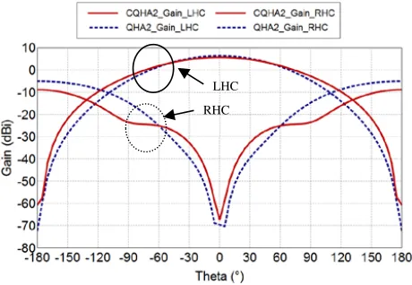
In order to perform one port radiation pattern measurement of the CQHAs, a feeding network based on commercially available couplers and phase shifters was fabricated. The average insertion loss of the feeding network was found to be 3.7 dB with a minimum reflection coefficient at the antenna terminals of −35 dB at 155 MHz. The measured phase progression between two adjacent ports at the output of the feeding network (the input of the QHA2/CQHA2) is 91.6◦ (port 1 to 2), 90.8◦ (port 2 to 3) and 89.8◦ (port 3 to 4), respectively. Fig. 8 shows the simulated co-polarization (LHC) and cross-polarization (RHC) components of the gain for QHA2 and CQHA2 at 162 MHz. As represented in Fig. 8, CQHA2 fulfills the requirements for a TTC application implemented by the goal function (Eq. (5)). The supporting thin dielectric film (paper for CQHA2a and PET for CQHA2b) was not taken into account in the simulation model.
Figure 9 shows the measured directivity (LHC and RHC components) of CQHA2a as a function of angle θfor two cut planes: φ= 0◦ and φ= 90◦.
LHC
RHC
Figure 8. Simulated co-polarization (LHC) and cross-polarization (RHC) components of the gain for the reference antenna QHA2 and the compact antenna CQHA2a.
CQHA2a RHC (0 ) QHA2 RHC (0 ) QHA2 LHC(0 ) CQHA2a LHC(0 ) QHA2 LHC(90 ) QHA2 RHC(90 ) CQHA2a LHC (90 ) CQHA2a RHC (90 )
-180 -150 -120 -90 -60 -30 0 30 60 90 120 150 180 Theta ( )o
10
0
-10
-20
-30
-40
Directivity (dBi)
o o
o o
o o o
o
Figure 9. Measured co-polarization (LHC) and cross-polarization (RHC) components of the directivity for the references antenna QHA2 and the compact antenna CQHA2a as function of theta angle (◦) for phi = 0◦ (xOy) and phi = 90◦.
5. CONCLUSION
Simulated and experimental results demonstrate that CQHAs with an axial height reduced up to 70% reported to the reference QHA can be obtained by using various shape profiles and an appropriate optimization method. The impact of the miniaturization on CQHA performances in terms of radiation pattern and polarization purity can be controlled and minimized in order to fulfil the technical requirements of a VHF TTC system. It was shown that the choice of the shape profile is not critical when relative height higher than 60% is required. Moreover, standard prefractal profiles such as Peano and Von Koch shapes cannot provide very compact structures. The impact of the shape is critical on the gain for very compact quadrifilar helix antennas (i.e., when relative height lower than 40% is required). In order to estimate the gain achievable by CQHA, a practical closed-form equation, very useful from a system design point of view, was derived from extensive numerical data. It was established that whatever the chosen profile is, the gain of CQHA normalized by the gain of the reference QHA equals the height of the CQHA normalized by the height of the QHA.
ACKNOWLEDGMENT
This work was supported in part by the CNES (French Space Agency) under the grant Ref. DCT/RF/AN — 2011.0011001 (2011) and DCT/RF/AN — 2009.0009307 (2009).
The authors acknowledge the technical support of Xavier Dollat and Antony Coustou (CNRS-LAAS), Tonio Idda (former CNRS-(CNRS-LAAS), Emanouil Koufidakis and Nelson Fonseca (former CNES), Mingtian Wang (University of Toulouse) and Mohamed Fodil (former University of Toulouse) for their contributions in the different phases of this research work.
REFERENCES
1. Balanis, C. A., Modern Antenna Handbook, John Willey & Sons, 455–457, 2008.
2. Kilgus, C. C., “Resonant quadrifilar helix,” IEEE Trans. on Antennas and Propagation, Vol. 17, No. 3, 349–351, May 1969.
4. Kilgus, C. C., “Resonant quadrifilar helix design, technical feature,” Microwave Journal, 49–54, Dec. 1970.
5. Kilgus, C. C., “Shaped-conical radiation pattern performance of the backfire quadrifilar helix,”
IEEE Trans. on Antennas and Propagation, Vol. 23, No. 3, 392–397, May 1975.
6. Takacs, A., N. J. G. Fonseca, and H. Aubert, “Height reduction of the axial-mode open-ended quadrifilar helical antenna,” IEEE Antennas and Wireless Propagation Letters, Vol. 9, 942–945, 2010.
7. Amin, M. and R. Cahil, “Compact quadrifilar helix antenna,” IET Electronics Letters, Vol. 41, No. 12, 672–674, Jun. 2005.
8. Amin, M., R. Cahil, and V. F. Fusco, “Mechanically tunable multiband compact quadrifilar helix antenna with dual mode operation,” IEEE Trans. on Antennas and Propagation, Vol. 56, No. 6, 1528–1532, Jun. 2008.
9. Amin, M. and R. Cahil, “Effect of helix turn angle on the performance of a half wavelength quadrifilar antenna,” IEEE Microwave and Wireless Propagation Letters, Vol. 16, No. 6, 384–386, Jun. 2006.
10. Auriol, A., “Helix-type antenna and its manufacturing process,” European Patent, publication number: 0320404A1, Jun. 14, 1989.
11. Adams, A., R. Greenough, R. Wallenberg, A. Mendelovicz, and C. Lumjiak, “The quadrifilar helix antenna,” IEEE Trans. on Antennas and Propagation, Vol. 22, No. 2, 173–178, Mar. 1974.
12. Ibambe, M. G., Y. Letestu, and A. Sharaiha, “Compact printed quadrifilar helical antenna,”IET Electronics Letters, Vol. 43, No. 13, 697–698, Jun. 21, 2007.
13. Chew, D. K. C. and S. R. Saunders, “Meander line technique for size reduction of quadrifilar helix antenna,” IEEE Antennas and Wireless Propagation Letters, Vol. 1, 109–111, 2002.
14. Bhandari, B., S. Gao, and T. Brown, “Meandered variable pitch angle printed quadrifilar helix antenna,” Proc. of LAPC’2009, 325–327, Loughborough, UK, Nov. 16–17, 2009.
15. Hanane, L., S. Hebib, H. Aubert, and N. J. G. Fonseca, “Antenna of the helix type having radiating strands with a sinusoidal pattern and associated manufacturing process,” Patent International Publication Number WO 2009/034125 A1, Mar. 19, 2009.
16. Back, J., J. Zackrisson, M. Ohgren, and P. Ingvarson, “A new quadrifilar helix antenna family with flexible coverage for space applications,” Proc. of EuCAP 2007, 1–6, Edinburgh, UK, Nov. 11–16, 2007.
17. Mirkamali, A., L. Akhoondzadeh, K. Keyghobad, and M. Soleimani, “A novel quadrifilar helix antenna for use in LEO satellite communications,”Proc. of International Conf. on Antenna Theory and Techniques, 509–511, Sevastopol, Ukraine, Sep. 9–12, 2003.
18. Son, W. I., W. G. Lim, M. Q. Lee, S. B. Min, and J. W. Yu, “Printed square quadrifilar helix antenna (QHA) for GPS receiver,” Proc. of EUMC’2008, 1292–1296, Amsterdam, Netherlands, Oct. 2008.
19. http://smsc.cnes.fr/SVOM/Fr/GP satellite.htm.
20. Inoue, J., “Helical antenna,” International Publication Number WO 01/24315, Apr. 4, 2001. 21. Saunders, S. R. and D. Kwan Chong Chew, “Multifilar helix antennas,” US Patent 7,142,170 B2,
Nov. 28, 2006.
22. Fonseca, N., S. Hebib, H. Aubert, and L. Hanane, “Helix antenna,” Patent International Publication Number WO 2008/142099 A1, Nov. 27, 2008.
23. Ermutlu, M. and K. K.-P. Kiesi, “Multi-filar helix antennae,” US Patent 6,232,929 B1, May 15, 2001.
24. Aubert, H., H. Diez, D. Belot, and A. Takacs, “Compact helical antenna with a sinusoidal profile modulating a fractal pattern,” Patent International Publication Number WO 2013139935 A1, 2013. 25. Fonseca, N. and H. Aubert, “Compact helical antennas — A review,”Recent Patents Electr. Eng.
J., Vol. 9, 942–945, 2010.
No. 3, 202–207, Feb. 19, 2013.
27. Takacs, A., T. Idda, H. Aubert, and H. Diez, “Compact VHF quadrifilar helix antenna,” Proc. of EUMC’2012, Amsterdam, Netherlands, Oct. 28–Nov. 2, 2012.
28. Fonseca, N. J. G., A. Takacs, and H. Aubert, “Design and experimental validation of a compact quadrifilar helix antenna in VHF band,”Proc. of APMC 2009, Singapore, Dec. 7–10, 2009. 29. Takacs, A., N. J. G. Fonseca, H. Aubert, and X. Dollat, “Miniaturization of quadrifilar helix antenna
for VHF band applications,”Proc. of LAPC’2009, 597–600, Loughborough, UK, Nov. 16–17, 2009. 30. Modern Plastics Encyclopaedia, McGraw Hill, New York, 1981–1982.
31. www.inkjetflex.com.