© 2017, IJCSMC All Rights Reserved
59
Available Online atwww.ijcsmc.comInternational Journal of Computer Science and Mobile Computing
A Monthly Journal of Computer Science and Information Technology
ISSN 2320–088X
IMPACT FACTOR: 6.017IJCSMC, Vol. 6, Issue. 10, October 2017, pg.59 – 66
Microwave Isolator
1
Mrs. Smita Desai,
2Mr. Amit Uppin,
3Miss. Shreya Desai
1
Department of Computer Science, Bharatesh College of Computer Applications, Belagavi, Karnataka, India [email protected]
2
Electronics and Communications, KLE‟s Dr. M.S. Sheshgiri, College of Engineering and Technology, Belagavi, Karnataka, India [email protected]
3
Electronics and Communications, Gogte Institute of Technology, Belagavi, Karnataka, India [email protected]
Abstract— This paper looks into different specifications of the isolator and what they mean. After knowing the specifications and the dimensions required we need to find out the type of ferrite to be used. Because our main aim in this research is not to design the isolator but to find out the type of isolator ferrite to be used by performing a literature survey of current ferrites used in isolator and find the one that best suits our needs. Important applications of ferrite materials, negative index, electro-magnetic interference suppression are discussed in this paper. Here we review the recent advancements in the processing isolator ferrites.
Keywords— Microwave Isolator, ferrite, Isolator Ferrite, microwave heating, microwave circulator.
I. INTRODUCTION
Microwave heating is an emerging field of technology in RF that is quick and efficient for materials that are difficult to heat by
conventional methods like convection or infrared. There are many important applications to microwave heating forefront of
them being food processing but on an industrial scale it is effective in many other products like Rubber- gaskets, Ceramics-
catalytic converters in cars and chinaware, Investment casting waxes. There are many other unexplored heating applications
where conventional heating methods might be less effective. The direct and efficient heat offered by microwave can have many
advantages, they include-Quicker heat penetration- Microwave energy can penetrate into the homogeneous material and heat
the complete profile more uniformly than conduction. There is no need to wait for the heat to reach the interiors of the material,
Selective heating- Since different materials respond to microwave in different ways product with many components can be
heated selectively, Increased flexibility- Complex shapes can be heated more uniformly with microwave energy, Combination
with conventional methods- Microwave heating can be done before or after conventional heating to decrease production times
by as much as 75%, High energy efficiency-As a measure of heat energy input to the material versus ac line power supplied to
© 2017, IJCSMC All Rights Reserved
60
to 30%efficient. So, although electricity is more expensive than gas or oil, the benefits of microwave heating can be realized
without any increase in energy costs. Applications of microwave heating-
Rubber-Microwave heating saves energy during batch preheating of rubber before moulding into parts such as gaskets.
It has converted rubber vulcanization, required for strength and resiliency, from a batch process to a continuous one.
Heating by hot air, autoclaves, or salt baths is slow and difficult because rubber conducts heat poorly but microwave
energy rapidly heats the rubber within its bulk, up to five times faster than hot air heating.
Investment casting-Microwave heating can help convert investment casting for precision parts such as turbine blades
from a batch process to a continuous one. Refractory moulds for the parts are formed around a wax model. Microwave
energy heats the mould, melting the wax. The wax runs out of the mould and is collected for reuse, while the shell
remains for casting. By using microwave heating instead of autoclaves for dewaxing, manufacturers have
Reduced energy requirements by90%
Reduced labour in dewaxing, firing and cleaning the moulds by 80%
Recovered wax for reuse
Improved product quality
Frozen food tempering-Tempering of frozen foods, raising the temperature from 0 F, at which foods are solidly frozen,
to 18 F to 20 F greatly facilitates their processing. Frozen food tempering represents the single largest industrial use of
microwave heating in the United States. Much of this country's processed meat, such as hamburger, sausage, canned
meat, and pet foods, contains significant amounts of ingredients that have been frozen and later tempered to permit
further processing.
Applying electromagnetic energy at microwave frequencies is an effective way to heat non conducting materials because
the energy is transferred directly to the molecules of the material. The material‟s molecules become simulated and rotate
millions of times in a second in response to the electromagnetic field. This rotation quickly generates heat within the
material in a manner similar to friction.
© 2017, IJCSMC All Rights Reserved
61
I. UNDERSTANDINGCERTAINTERMSANDPARAMETERSThe operating parameters on which to select our isolator.
A. VSWR
This parameter specifies to what degree the input signal will be reflected back toward the source. For critical applications the magnitude and phase of the reflected signal can be provided as an impedance plot recorded on a smith chard.
B. Insertion Loss
It is the ratio of the output signal strength to the input signal expressed in DB when the signal is applied in the low loss direction to the circulator and isolator.
C. Isolation Loss
When applied to the isolator is high loss direction the ratio of output signal strength to the input signal expressed in DB.
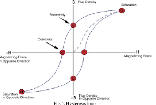
D. Magnetic Saturation
Magnetic saturation is the state reached when an increase in applied external magnetic field H cannot increase the magnetization of the material further.
So the total magnetic flux density B more or less levels off. (Increases very slowly)
µ=B/H
Ferromagnetic materials like iron are composed of microscopic regions called magnetic domains, which act like tiny permanent
magnets that can change the direction of magnetization.
When an external magnetizing field H is applied to the material it penetrates the material and aligns the domain causing tiny
magnetic fields to turn and align parallel to the external field. This causes a large magnetic field B to extend out of material this
is magnetization. Eventually at a certain point the domain walls have moved as far as they possibly can and are aligned in
crystal structure so they cannot go anywhere.
E. Coercively
Is the resistance of a magnetic material to changes in magnetization (Measured by magnetic hysteresis loop).
F. Hysteresis Loop
A hysteresis loop shows the relationship between the induced magnetic flux density (B) and the magnetizing force (H). It is often referred to as the B-H loop.
© 2017, IJCSMC All Rights Reserved
62
G. Permittivity ƐIt is a measure of resistance that is encountered when forming an electric field in a particular medium. Permittivity denotes the amount of charge needed to generate on unit of electric flux in particular medium.
H. Permeabilityµ
Ability to apply H magnetic field and how much the magnetic flux density is increased or how much electric flux is generated.
I. Curie temperature
Curie temperature (Tc) is a temperature at which certain materials lose their permanent magnetic properties to be replaced by induced magnetism.
III. UNDERSTANDINGCIRCULATORSANDISOLATORS
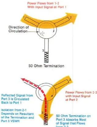
A. Microwave Circulator
Before understanding Isolators let us first understand the working of a circulator-
A circulator is a passive non reciprocal three or four port device in which a microwave or radio frequency signal entering any
port is transmitted to the next port in rotation.
Fig. 3 Symbolic expression for a Y-junction circulator
Each port is connected only to next port but not to others.
B. Microwave Isolator
© 2017, IJCSMC All Rights Reserved
63
When one port of a three port circulator is terminated in a matched load, it can be used as an isolator, since a signal can travel in only one direction between the remaining ports. An isolator is used to shield equipment on its input side from the effects of conditions on its output side; for example, to prevent a microwave source from being detuned by a mismatched load.
An isolator is a 3 port device made up of waveguides with ferrites at the junction and magnets to bias the ferrites with magnetic field. If a signal were applied at port 1 the two waves will arrive in phase at port 2 and cancel at port 3. Maximum power transfer will occur from port 1 to 2 and minimum transfer will occur from port 1 to 3, depending on the direction of the applied magnetic field. The selection of basic ferrite material and magnet material has a significant effect on the overall performance and cost of the circulators and isolators. A ferrite disk and the intersection of 3 transmission lines from the Y junction is where the actual circulation occurs. A signal applied to a ferrite disk will generate two equal, circularly polarized counter-rotating waves that will rotate at velocities Gama+ and Gama-. The velocity of a circularly polarized wave as it propagates through a magnetically biased microwave ferrite material will depend on its direction of rotation.
Without a permanent magnetic field a wave entering port 1 is split into two rotating waves with the same propagation speed, one rotating clockwise, the other anti-clockwise, which is coupled to port 2 and port 3. The incoming wave is divided and half of the power leaves port 2 and the other half port 3.
With a permanent magnetic field supplied perpendicular to the ferrite discs, the propagation speed of the two rotating waves is no longer the same. The wave rotating clockwise has now the propagation speed of gamma+, the wave rotating anti-clockwise the propagation speed gamma+. This results in a rotation of the standing wave pattern. By increasing the magnetic field the standing wave pattern rotates anti-clockwise. If the angle of rotation is 30 degrees, the device is a circulator: Port 3 is decoupled and all the energy passes from port 1 to port 2.
After understanding what an isolator let us see how to calculate the dimensions and what the required specifications are. Now if we use a much higher magnetic field and adjust it so, that the standing wave pattern is rotated by 30 degrees clockwise, port 2 is decoupled and all energy passes from port 1 to port 3.
So for the first mode of operation we need a static magnetic field lower than for putting the ferrite into resonance, therefore this mode is called below resonance, for the second mode of operation the magnetic field is higher than for resonance, therefore we call this mode as above resonance. Circulators are made as above resonance circulators in the frequency range 150 MHz to about 2 GHz and as below resonance circulators in the frequency range 1.5 to 20 GHz. The dimension of the outer magnets is chosen based on the magnetic flux density required to saturate the ferrites, the saturation magnetic flux density is dependent on the ferrite material. Now let us understand how ferrites work on a deeper level.
When a ferrite material is magnetized the magnetic moments of the electrons energize at a frequency proportional to the biasing magnetic field. Ferromagnetic resonance occurs when a rotating RF magnetic field has the same direction and frequency as the processing electrons in the ferrite material. Maximum coupling of the energy from the RF signal to the ferrite material will occur at ferromagnetic resonance if the direction of rotation or the frequency of the RF signal is changed. Minimum coupling will occur.
Fig.5 Ferromagnetic resonance
Biasing the junction circulator at ferromagnetic resonance is not desirable since the circulator would be extremely lossy. Since it has low field it is not biased enough hence loss.
IV. UNDERSTANDINGFERRITES
© 2017, IJCSMC All Rights Reserved
64
A. Hard ferritesHard ferrites have high coercively, hence they are difficult to demagnetize. They are used to make magnets for devices such
as magnets, loud speakers and small electric motors.
B. Soft ferrites
Soft ferrites have low coercively.
They are used in electronic industry to make ferrite cores of inductors and transformers and importantly microwave components.
Ferrites that are used in transformers or electromagnetic cores contain nickel, zinc or manganese compounds.
They have low coercively meaning the material‟s magnetization can be easily be reversed direction without dissipating much energy.
They have high retentively which prevents eddy currents.
They have comparably lower losses at high frequencies hence used in isolators. Some examples are Manganese- Zinc ferrite (MnZn), NiZn (Nickel-Zinc ferrite) For below 5MHz MnZn ferrites are used.
NiZn they exhibit more resistivity than MnZn and are more suitable for frequencies greater than 1MHz.
C. Design specifications
WR340 or WR430:
The numbers denote length and the breadth in inches. Converted from being 340 to 3.4 inches as one side and half this number as the other side of the rectangular waveguide. For 340 it is 3.4 inches and for 430 it is 4.3 inches. Required frequency of operation- 2.45 GHz.
Basically ferrites are ceramic materials dark grey or black in appearance and very hard and bitter. They are materials containing ferric ions as the main constituent. Ferrites can be divided into 3 important classes with each one having specific crystal structure.
1. Soft ferrites with garnet structure. E.g.-Microwave ferrites (YIG)
2. Soft ferrites with cubic spinel structure such as NiZn, MnZn and MgMnZn ferrites. 3. Hard ferrites with magnetoplumbite (Hexagonal) structure such as Ba or Sr ferrites.
On the basis of the crystal structure ferrites can be classified into- 1. Spinel Ferrite
2. Hexagonal ferrite. 3. Garnet ferrites.
V. LITERATURESURVEY
As the ferrite will be operating at Microwave (high) frequency ranges and at high frequency ranges the magnets tend to get easily saturated and if that happens it would fail to function as a proper isolator in its full capacity [1].
We also need to find out the relationship between magnetic saturation and maximum temperature of operation. For our current research we have concentrated on magnetic saturation and the link between maximum temperatures.
A good microwave ferrite isolator needs to have high magnetic saturation, so the ferrites that have high magnetic saturation for our application is Garnet ferrite structure.
© 2017, IJCSMC All Rights Reserved
65
TABLEIYTTRIUM
-
ALUMINUMType Magnetic saturation (Gauss) Max Temperature (C)
Y31 370 125
Y36 290 115
TABLE II
YTTRIUM
-
ALUMINUM-
GADOLINIUMType Magnetic saturation (Gauss) Max Temperature (C)
Y75 400 160
Y76 390 150
There have been new ranges of microwave ferrites discovered which have a magnetic saturation between 200G to 900G which exhibit higher temperature stabilities of magnetization than those of classical garnets.
These properties, obtained by a judicious balance between both substitutions, make these materials suitable for applications in the lower frequency range of the microwave spectrum when high peak and average power are needed [2].
The main take away points from this research are two things. 1. Variation of magnetic saturation with the composition.
2. Variation of magnetic saturation with respect to Curie temperature.
© 2017, IJCSMC All Rights Reserved
66
Next the saturation magnetization at room temperature versus aluminum content was observed to be-We can see that as the composition of aluminum went on increasing the Magnetic saturation went on decreasing. This research helped paved the path for better compositions which performed better as we shall see later.
VI. CONCLUSIONS
We can see that with increase in temperature the magnetic saturation kept falling and the magnetic saturation was the highest at the lowest temperature. We also observe with further proof that as magnetic saturation increases, the Curie temperature or temperature stability decreases. The variations with temperature show that this offers lower temperature stability but has lower losses
Thus we can deduce that as magnetic saturation increases the temperature stability decreases.
R
EFERENCES
1. „The Wiley Encyclopaedia of RF and Microwave Engineering *Ferrite isolators*‟ by B. Bayard, B. Sauviac & D. Vincent
2. INTERESTING MICROWAVE FERRITES OF POLYCRYSTALLINE Y Gd I G's WITH BOTH OCTAHEDRAL AND TETRAHEDRAL SUBSTITUTIONS By- R. SROUSSI and J. NICOLAS
3. J. Breckling, Ed., The Analysis of Directional Time Series: Applications to Wind Speed and Direction, ser. Lecture Notes in Statistics. Berlin, Germany: Springer, 1989, vol. 61.
4. S. Zhang, C. Zhu, J. K. O. Sin, and P. K. T. Mok, “A novel ultrathin elevated channel low-temperature poly-Si TFT,” IEEE Electron Device Lett., vol. 20, pp. 569–571, Nov. 1999.
5. M. Wegmuller, J. P. von der Weid, P. Oberson, and N. Gisin, “High resolution fiber distributed measurements with coherent OFDR,” in Proc. ECOC’00, 2000, paper 11.3.4, p. 109.
6. R. E. Sorace, V. S. Reinhardt, and S. A. Vaughn, “High-speed digital-to-RF converter,” U.S. Patent 5 668 842, Sept. 16, 1997. 7. (2002) The IEEE website. [Online]. Available: http://www.ieee.org/
8. M. Shell. (2002) IEEEtran homepage on CTAN. [Online]. Available: http://www.ctan.org/tex-archive/macros/latex/contrib/supported/IEEEtran/ 9. FLEXChip Signal Processor (MC68175/D), Motorola, 1996.
10. “PDCA12-70 data sheet,” Opto Speed SA, Mezzovico, Switzerland.
11. A. Karnik, “Performance of TCP congestion control with rate feedback: TCP/ABR and rate adaptive TCP/IP,” M. Eng. thesis, Indian Institute of Science, Bangalore, India, Jan. 1999.
12. J. Padhye, V. Firoiu, and D. Towsley, “A stochastic model of TCP Reno congestion avoidance and control,” Univ. of Massachusetts, Amherst, MA, CMPSCI Tech. Rep. 99-02, 1999.