Using Dc Resistive Fault Current Limiter to Enhancement of Dfig Based
Variable Speed Wind Generator at Symmetrical Fault Condition
P.Varshini & Dr.A.Sateesh Kumar
1m.Tech, Vaagdevi College Of Engineering, Bollikunta, Warangal. 2assistant Professor, Vaagdevi College Of Engineering, Bollikunta, Warangal.
Abstract—In this paper proposes a doubly fed induction machine transient stability is one of the important factors which we have to consider improving performance of wind generator. The symmetrical faults, the asymmetrical faults also may cause the DFIG face high mechanical stress which may lead to mechanical damage. Therefore, it is very important to investigate the fault ride through (FRT) capability of the DFIG system during the asymmetrical fault situations. In this work, in order to enhance the FRT capability of the DFIG based wind generation system, a DC resistive superconducting fault current limiter (SFCL) is proposed. In this work, in request to improve the FRT ability of the DFIG based wind generation system, a DC resistive Superconducting Fault Current Limiter (SFCL) is proposed. The performance of the proposed method is better than that of the BFCL. By using the simulation results we can analyse the proposed DC resistive SFCL improves the FRT ability of the DFIG based variable speed wind generator system during any type of asymmetrical faults in the power network.
Keywords— bridge type fault current limiter (BFCL), doubly fed induction generator (DFIG), fault ride through (FRT), superconducting fault current limiter (SFCL), wind energy conversion system (WECS)
I. INTRODUCTION
With an increase electrical power demand renewable energy resources play an important role now-adays to compete with electrical power demand to provide power quality to the end user. Amid of renewable energy resources wind energy is the fast growing and prominent to generate electrical power with less fuel cost. Due to flexible operation higher output power, higher efficiency, no fuel cost, provide power quality and low mechanical stress on turbine. Compare to variable speed wind generators having high rated full converters, DFIM wind generators are more efficient in this stator windings are directly connected to grid and rotor windings are connected to grid by rotor side converter(RSC) and grid side converter(GSC) are connected back to back through a dc link capacitor.
The DFIG system is presently a very popular technology to harness electricity from the wind energy. To operate reliably, the wind energy conversion system (WECS) should have the ability to maintain synchronism when subjected to a severe disturbance, such as a short circuit on a transmission line. The wind generator should also have the low and high voltage ride through capability, i.e., the wind generator should remain connected with the grid if the voltage is lower or higher than the rated voltage, respectively, due to any problem of the system [1]. During asymmetrical faults, negative-sequence voltages become destructive to the DFIG than the positive-sequence components, since they induce higher voltages in the rotor windings [2]. Therefore, it is very important to investigate
the fault ride through (FRT) capability of the DFIG system under the asymmetrical fault conditions. The series and shunt compensating Flexible AC Transmission System (FACTS) devices support the WECS to maintain the FRT ability [1].
Although the SFCL improves the FRT capability of the wind power system [7], [9], using the SFCL introduces significant system losses during normal operation of the system [10], and hence reduces the overall system efficiency. To overcome this problem, a novel DC resistive SFCL is analysed.
Based on the above background, this paper proposes the DC resistive SFCL to enhance the asymmetric FRT capability of a DFIG based WECS. In order to show the ability of the proposed scheme, its performance is compared with that of the BFCL.
II. POWER SYSTEM MODEL UNDER STUDY
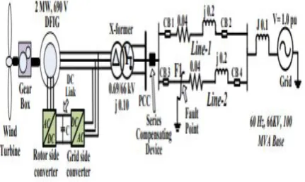
In this research, a 2 MW 690 V DFIG based WECS has been modelled to analyze the transient stability. All the considered parameters to model the DFIG are shown in Table I. The DFIG is connected with the infinite bus through a step up transformer and double circuit transmission lines, as shown in Fig. 1.
Fig. 1. Simulated power system model.
The series compensating device, i.e., the DC resistive SFCL, or the BFCL is connected in series at the terminal of the wind generator which is known as ‘point of common coupling (PCC).’ The effectiveness of the proposed methodology is tested considering temporary unbalanced faults at point F1 in the power system of Fig. 1.
III. WIND TURBINE MODELING
The mechanical power, P, captured by a horizontal axis wind turbine can be expressed as follows
𝑃 =1
2. 𝜌. 𝜋𝑅 2𝑉
𝜔3𝐶𝑝(𝜆, 𝛽) (1)
which is a function of both tip speed ratio, λ, and blade pitch angle, β. According to Betz, theoretically up to 59% power can be extracted from the wind [1]. The tip speed ratio is defined as,
𝜆 =𝑅𝜔
𝑉𝜔 (2)
Here, ω is the mechanical angular velocity of the turbine in rad/s. For the wind turbine modeling, the following Cp (λ, β) equation is considered in this work 𝐶𝑝(𝜆, 𝛽) = 𝑐1(
𝑐2
𝜆𝑖− 𝑐3𝛽 − 𝑐4) 𝑒
−𝑐5
𝜆𝑖 − 𝑐6𝜆 (3)
Where
𝜆𝑖= [
1
𝜆 + 0.08𝛽−
0.035 𝛽3+ 1]
−1
TABLE I. PARAMETERS OF THE DFIG SYSTEM
IV. DOUBLY-FED INDUCTION GENERATOR (DFIG) MODELING
The basic configuration of a DFIG based wind turbine is shown in Fig. 1, where the stator of the machine is directly connected with the grid through a transformer, and the wound rotor is also connected to the grid with the help of AC-DC and DC-AC converters. Two three-phase pulse width modulated (PWM) voltage source converters, i.e., the rotor side converter (RSC) and grid side converter (GSC) are coupled to a common DC link. In this research, the vector control method [12] has been used to control the RSC and GSC controllers of the DFIG.
A. Rotor Side Converter (RSC) Controller
The rotor side converter (RSC), shown in Fig. 2, is used to control both the active power and reactive powers of the stator’s terminal of the DFIG [12]. The RSC is a power electronic full bridge 2-level, 6-pulse converter that converts the dc voltage of the dc link into ac voltage, and connects to the rotor of the machine. The RSC controller takes the terminal active power Ps and the reactive power Qs as inputs and controls the output active and the reactive powers. The PWM generates pulses for switching the RSC.
Fig. 2. Rotor side converter (RSC) controller.
B. Grid Side Converter (GSC) Controller
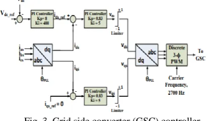
The grid side converter (GSC) controller, shown in Fig. 3, takes the DC link voltage and the rotor line reactive power as inputs to regulate the voltage of the DC link, and generates an independent reactive power that is injected into the grid [12].
Fig. 3. Grid side converter (GSC) controller. The GSC in the rotor circuit always controls the reactive power to zero. That is why, here iqs_ref is considered to be zero. The GSC ensures the energy balance on both sides of the dc-link by maintaining the fixed dc-link voltage
V. DC RESISTIVE SFCL
A. DC resistive SFCL configuration and operation
The construction of the DC resistive SFCL is a combination of rectifier and resistive type SFCL shown in Fig. 4 (a), where a low inductance superconducting coil is designed in order to quench when the current flows over the rated value.
(a)
the current (ISFCL) flowing through the superconducting coil is unidirectional. This helps reduce the AC losses in the superconductor, and hence improves the efficiency. Though there are some power losses across the rectifier diodes, using the DC resistive SFCL provides better system efficiency even considering these losses [11].
B. DC resistive SFCL Control strategy
During any disturbances of the system, the line voltage, line current, DC link voltage of the DFIG, active and reactive powers through the line are highly affected. Usually these changes are considered to control the auxiliary devices. One of the main advantages of using the SFCL is that no additional controller is required for the DC resistive SFCL. The DC resistive SFCL remains connected in series with the system all the time. During simulation, the property of the DC resistive SFCL is maintained by varying the resistor (RSC) value. During steady operation the value RSC is kept zero. Only during the fault, the value of the quenched resistance, RSC, is considered 0.63 p.u., which is determined by trial and error approach based on the machine rating.
VI. BFCL CONFIGURATION AND CONTROL
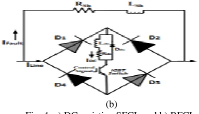
The BFCL, shown in Fig. 4 (b), consists of two parts- i) bridge part, and ii) shunt part [3], [8]. Like the bridge configuration of the DC resistive SFCL, the bridge part consists of four diodes D1-D4.
(b)
Fig. 4. a) DC resistive SFCL and b) BFCL. A small value of the dc reactor, Ldc (5 mH) is connected in series with the IGBT switch. Rdc is the inherited resistance of Ldc which is very low as 0.1mΩ. Usually the IGBT switch is designed with the freewheeling diode, which is not shown here. For the safe operation, Ldc is equipped with the freewheeling diode, Ddc. The shunt path is composed of a resistor Rsh and an inductor Lsh. During the simulation, the same value of 0.63 p.u. resistance as the SFCL is also considered for the Rsh of the BFCL to make the comparative study rational. As the impedance of the shunt path is high, current flows through the bridge fully except very small leakage current. Ddc provides the path to discharge the residual reactor current in order to avoid the high transient current for the switching of the IGBT. After the fault clearance, controller turns on the IGBT to resume the normal operation of the bridge part of the BFCL.
VII. SIMULATION RESULTS WITH DISCUSSIONS
A. Simulation considerations
The temporary asymmetrical faults, such as, (i) double-line-to-ground (2LG), (ii) line-toline (LL) and (iii) single-line-to-ground (1LG) faults are considered to occur separately at point ‘F1’ of Fig. 1 at 0.1 s. The fault persists for the duration of 0.42 s. Circuit breakers CB3 and CB4 are opened at 0.1833 s, and reclose at 1.0163 s. During simulation, three types of situations are considered- i) fault analysis without any controller, ii) fault analysis with the DC resistive SFCL, and iii) fault analysis with the BFCL.
Fig.6. LL falut
Fig.7. LLG fault
B. Asymmtrical fault analysis
The response of the DFIG terminal voltage, speed, DC link voltage, and absorbed power by the auxiliary devices during the 2LG, LL and 1LG faults for all the three aforementioned conditions are shown in Figs. 5, 6 and 7, respectively. From all the simulation results, it is clearly visualized that, both the auxiliary devices, i.e., the DC resistive SFCL and the BFCL help improve the FRT capability of the DFIG based WECS. From the fault initiation to the circuit breaker opening, the DC resistive SFCL consumes more active power than the BFCL during all the asymmetrical type faults, which assists the DC resistive SFCL to provide better compensation than the BFCL.
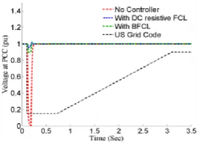
C. Low voltage ride through (LVRT) investigation at PCC
In this study, the PCC voltage for both the 2LG and LL faults falls closer to zero without any controllers. This violates
Fig. 8. PCC voltage and LVRT specification in US during 2LG fault.
the United States (US) grid code to keep the DFIG system connected with the PCC, as all the modern grid codes demand the wind farms stay connected with the power network, even during the faults [14]. In Fig. 8, only the PCC voltage during the 2LG fault along with US grid code is presented. To conform to the grid code, a larger timeframe of simulation is considered.
TABLE II. PERFORMANCE INDICES DURING THE ASYMMETRIC FAULTS
In this paper, the utilization of DC resistive SFCL to enhance the FRT capacity of a DFIG based wind control system is presented. A doubly fed induction machine transient stability is one of the important factors which we have to consider improving performance of wind generator. The application of DC resistive SFCL to improve the FRT capability of a DFIG based wind power system has been analysed and compared with the BFCL. Voltage sag and high level of fault current are significantly suppressed by the DC resistive SFCL. The DC resistive SFCL provides better performance than the BFCL. As SFCL is a very effective tool to enhance the FRT capability, its cost minimization can be an important direction of research as well. By using the simulation results we can analyze the proposed DC resistive SFCL is capable to enhance the FRT ability of the DFIG system during the asymmetrical fault conditions.
REFERENCES
[1] M. M. Hossain and M. H. Ali, “Future research directions for the wind turbine generator system,” Renew. Sustain. Energy Rev., vol. 49, pp. 481–489, 2015. [2] H. Geng, C. Liu, and G. Yang, “LVRT capability of DFIG-based WECS under asymmetrical grid fault condition,” IEEE Trans. Ind. Electron., vol. 60, no. 6, pp. 2495–2509, 2013.
[3] G. Rashid and M. H. Ali, “Bridge-Type Fault Current Limiter for Asymmetric Fault Ride-Through Capacity Enhancement of Doubly Fed Induction Machine Based Wind Generator,” in Proc. IEEE Energy Convers. Congr. Expo. (ECCE), 2014, pp. 1903 – 1910.
[4] N. G. Hingorani and L. Gyugyi, Understanding FACTS: concepts and technology of flexible AC transmission systems. 2000.
[5] H. A. Mohammadpour and E. Santi, “Sub-synchronous resonance analysis in DFIG-based wind farms: Mitigation methods — TCSC, GCSC, and DFIG controllers — Part II,” in Proc. IEEE Energy Convers. Congr. Expo. (ECCE), 2014, pp. 1550–1557.
[6] H. A. Mohammadpour and E. Santi, “Modeling and Control of GateControlled Series Capacitor Interfaced With a DFIG-Based Wind Farm,” IEEE Trans. Ind. Electron., vol. 62, no. 2, pp. 1022–1033, 2015.
[7] Y. Zhao, O. Krause, T. K. Saha, and Y. Li, “Stability enhancement in distribution systems with DFIG-based wind turbine by use of SFCL,” in Australasian Universities Power Engineering Conference, 2013. [8] G. Rashid and M. H. Ali, “Transient Stability Enhancement of Doubly Fed Induction Machine-Based Wind Generator by Bridge-Type Fault Current Limiter,” IEEE Trans. Energy Convers., vol. 25, no. 3, pp. 1–9, 2015.
[9] A. A. Hussein and M. H. Ali, “Comparison among Series Compensators for Fault Ride through Capability Enhancement of Wind Generator Systems,” Int. J. Renew. Energy Res., vol. 4, no. 3, 2014.
[10] S. Imparato, A. Morandi, L. Martini, M. Bocchi, G. Grasso, M. Fabbri, F. Negrini, and P. L. Ribani, “Experimental evaluation of AC losses of a DC restive
SFCL prototype,” IEEE Trans. Appl. Supercond., 2010, vol. 20, pp. 1199–1202.