Article
Investigating Non-Linear Dynamic Behavior of
Dual Steel Frames under the Effect of Near and
Far Fields to Fault
Hamid Reza Ashrafi 1, Soroush Dadgar 2 and Peyman Beiranvand 2,*
1 Assistant Professor, Department of Civil Engineering, Razi University of Kermanshah,
67149-67346 Kermanshah, Iran; [email protected]
2 Department of Civil Engineering, Razi University of Kermanshah, 67149-67346 Kermanshah, Iran;
* Correspondence: [email protected]; Tel.: +98-937-865-1620
Abstract: This study sought to investigate steel frames’ performance with dual lateral loader system
(Frame bending + bracings of divergent and convergent) in near and far filed to fault. In order to this, four categories of steel frame with dual system with 8, 10 and 12 story are designed with average formation based on existing seismic regulation in 2800 standard of Iran and tenth chapter of national regulations of construction (planning and performing steel construction). Time history non-linear dynamic analysis under the effect of near and far field earthquakes has been done on plan’s models. Then the maximum of floors’ dislocation, floors’ drift, roof dislocation, base shear and energy curves of frames are shown and compared with each other. All non-linear time history analyses have been accomplished using PERFORM 3D software.
Keywords: dual steel frame; far field from fault; near field to fault; time history non-linear
dynamic analysis
1. Introduction
Near-fault records are affected by various factors such as ruptured fault mechanisms, rapture protraction and path and position of record station locating relating to rapture protraction [1]. Among recent year’s earthquakes in world, Tabas earthquakes 1978, Northridge 1994, Kobe 1995, Chi-Chi 1999 and Bam earthquake 2003 have near fault records. In most of mentioned earthquakes, constructed structures near the fault which caused earthquake especially located structures in leading route along the rupture are seriously and more than expected damaged [2]. In February spectrum mapping, near fault earthquakes, spectrum range has its maximum in a small area or in another word in a particular period instead of having maximum value in a big periodic area. The existence of such these characteristics in near fault earthquakes cause that structure behavior leaves mode-like , where one or some mode of structure determine structure’s behavior, and becomes wavelike that in this model, structure’s behavior is because of collecting the effects of passing waves from structure [3]. Incidence of the pulse at the beginning of the record represents releasing significant movement energy in a short time because of fault fracture. In a short time range, big movement energy is applied to structure. This is considered as one of the most important features of earth’s moving records in near field to fault. In addition to creating intensity phenomenon in structures with long period, this case also causes that consuming materials in construction structures will be affected because of imposing power as hitting and structures shows more brittle behavior [4]. On the other hand since these pals movements are entered in short time so structure won’t have enough time to response these entered powers. Because of emerging intensity phenomenon in responses of structures with long periods and bridges with big craters, using response spectrum isn’t adequate alone to state real behaviors of these structures. Therefor in near fault areas using response spectrum isn’t enough alone
2 of 15
for structures especially those which are long and affected by entered powers because of earthquake and cannot state real behavior of structures affected by entered powers in above conditions [5].
Iran is one of the countries that has been damaged financially and affected by earthquake a lot so considering resistant systems against earthquake seems absolutely necessary. In steel buildings, bending frame system because of appropriate forming and the possibility of earthquake energy big waste is considered an ideal system. The main problem of this system is higher lateral displacement and in another word its inadequate hardness. One of most important and common methods for solving this problem is using dual systems that include steel bending frame and other resistant system that in fact is evolved form of bending frame system and removing its displacement problem. Different kinds of complementary systems of steel bending frame in dual frames are bracings of divergent and convergent. Divergent bracings generally include cross and chevron bracings (like number eight in Persian or upside down V). In this study the behavior of dual steel frames affected by near and fault earthquakes are investigated and analyzed. In order to this, the primary designing of frames have been accomplished using a static method based on 2800 standard of Iran and tenth chapter of national regulations of construction (planning and performing steel construction) and members’ sections were identified [6-7]. In order to time history non-linear dynamic analyses, mentioned frames were modeled another time in PERFORM 3D software and results have been shown in form of graphs [8].
2. Dual lateral loader systems
The idea of formation dual systems is the existence of a backup system for main system of structure. Generally speaking the first perception of this system was created based on investigating undamaged buildings after earthquake in 1906 of San Francisco. In these investigations it was seen that healthy building from earthquake had steel frames with filleting walls. First dual system used to be introduced as a primary system for hardness and a backup system for durability and resistance. This phrase can be stated more modernly as a primary system for service-accepting and a secondary system for formation. The most function of these systems for average height to high buildings. UBC regulations and following it Iran’s 2800 standard introduce these systems as a combination of bending frames and shear walls or anchored frames [9].
3. Analytical models’ characteristics
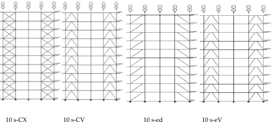
In this study, three models of 2D steel frames of 8, 10 and 12 stories have been designed with the number of craters equal with 4 with width of 5m and height of 3.2m. Mentioned frames are categorized in 4 categories of frames considering the kind of used cross brace in them. These categories include dual system frames having convergent cross and chevron bracing and having divergent diagonal and Chevron brace. Considering the resistance system duality against lateral loads, designing these frames has been done based on Iran’s 2800 standard. Based on this note, instead of distributing load to ratio of lateral loader elements’' rigidity in buildings with dual systems with braced frames, 100 percent of lateral power of earthquake can be applied to braces and eliminate comparing the rigidity of lateral loader elements only under the condition that frames be capable of 25 percent of lateral force. The primary designing of models was done using ETABS software and static analytical method. The importance coefficient of building I, is equal to 1, selected land is II and the location of building was assumed an area with relatively high earthquake risk [6-7, 10]. The weight of whole story in each one of models was determined as 400 kilo newton and the weight of roof as 300 kilo newton. For coping lateral loads, dual frame system consisting average steel bending frame + steel convergent bracing with behavior coefficient 7 were used. In figure 1 as an example, a view of 10 story frames related to each frame category has been shown. As following in tables 1 to 4 as samples, obtained sections for each 10 story model have been proposed.
3 of 15
10 s-CX 10 s-CV 10 s-ed 10 s-eV
Figure 1. A view of study frames
Preprints (www.preprints.org) | NOT PEER-REVIEWED | Posted: 15 October 2016 doi:10.20944/preprints201610.0063.v1
4 of 15
Table 1. Obtained sections for the 10s-cx model Table 2. Obtained sections for the 10s-cv model
Components sections Components sections
Floor A P
iers
AB
frame B P
iers
BC
frame C Piers CD frame D Piers DE frame E P
iers
AB
DE Floor A P
iers
AB
frame B P
iers
BC
frame C Piers CD frame D Piers DE frame E P
iers
AB DE
10 HE120 IPE240 HE100 IPE240 HE100 IPE240 HE100 IPE240 HE120
2U80 2U80
10 HE100 IPE200 HE100 IPE200 HE100 IPE200 HE100 IPE200 HE100
2U80 2U80
9 HE120 IPE270 HE120 IPE270 HE120 9 HE120 IPE240 HE120 IPE240 HE120 IPE240 HE120 IPE240 HE120 8
HE160 HE140 HE140 HE140 HE160
8 HE HE HE HE HE
7 7
HE16 HE16 HE16 HE16 HE16
6
HE180 HE180 HE180 HE180 HE180
2U100 2U100
6
HE180 HE180 HE180 HE180 HE180
5 5
2U100 2U100
4
HE200 HE200 HE200 HE200 HE200
4
HE200 HE200 HE200 HE200 HE200
3
IPE270 IPE270 3
IPE270 IPE270 IPE270 IPE270 2
HE240 HE240 HE240 HE240 HE240
2
HE240 HE240 HE240 HE240 HE240
1
HE260 HE260 HE260 HE260 HE260
1
HE260 HE260 HE260 HE260 HE260
Preprints (www.preprints.org) | NOT PEER-REVIEWED | Posted: 15 October 2016 doi:10.20944/preprints201610.0063.v1
5 of 15
Table 3. Obtained sections for the 10s-ed model Table 4. Obtained sections for the 10s-ev model
Components sections Components sections
Floor A P
iers
AB
frame B P
iers
BC
frame C Piers CD frame D Piers DE frame E P
iers
AB DE Floor
A P
iers
AB
frame B P
iers
BC
frame C Piers CD frame D Piers DE frame E P
iers
AB DE
10 HE100 IPE240 HE100 IPE240 HE100 IPE240 HE100 IPE240
HE100 2U100 2U100 10 HE100
IPE240 HE100 IPE240 HE100 IPE240 HE100 IPE240 HE100
2U80 2U80
9 HE120 IPE270 HE120 IPE270 HE120 IPE270 HE120 IPE270 HE120
2U120 2U120
9
HE120 HE120 HE120 HE120 HE120
8
HE140 HE140 HE140 HE140 HE140
8
HE140 HE140 HE140 HE140 HE140
7
HE180 HE180 HE180 HE180 HE180
7
HE180 HE180 HE180 HE180 HE180
6
2U140 2U140
6 IPE270 IPE270 5 HE20 IPE300 HE20 IPE300 HE20 IPE300 HE20 IPE300 HE20 5 IPE270 IPE270
4 HE HE HE HE HE
2U160 2U160
4 HE HE HE HE HE
3
HE24 HE24 HE22 HE24 HE24 3 HE22 HE22 HE22 HE22 HE22
2
HE26 HE26 HE24 HE26 HE26 2 HE26 HE24 HE24 HE24 HE26
2U100 2U100
1
HE280 HE280 HE280 HE280 HE280
1
6 of 15
In these frames, IPB profiles for columns, IPE profiles for beams and studs profiles have been used for bracings. It is noticeable that in order to comparison, designing trend has been assumed equal for all models. In modeling dual frame with convergent bracings, joining beam with length of 0.7 m was used that this value is smaller than . , so joining beam is capable of creating shear plastic
joint.
In order to summarize, an acronym was selected for each one of these models. From now on these names will be used for each one of them. Phrase 12s-cx is used for example for 10 story dual frame with convergent cross bracing in a way that first number represents the number of floors, first letter in second phrase represent frame’s convergent or divergent and last letter represent the kind of used bracing.
3.1 Story relative lateral displacement according to Iran’s 2800 standard regulations As an example for 8 story building with T=0.77:
∆ ≤ 0.002ℎ ↔ = 077 ≥ 0.7 , = 7
∆ = 0.7 ∆ → 0.7 ∆ ≤ 0.02ℎ → ∆ ℎ ≤
0.02
0.7 → = ∆
ℎ ≤ 0.00408 In a same way for frames of 10 and 12 story also, the rate of permitted relative movement is obtained as 0.00408. It is noticeable that these values in non-linear analysis will increase 0.7R and is respectively for frames of 8, 10 and 12 story equal to 0.02.
3.2 Non-linear behavior modeling of frame members in PERFORM 3D software
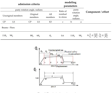
After designing in ETABS and identifying sections and doing necessary controls, models have been modeled another time in non-linear analysis software PERFORM 3D. Considering passing linear area and need to define characteristics and the way of material and member performance in non-linear area, regulations of FEMA 356 have been used [11]. In table 5 the time of obtained periodicity from linear or non-linear static analysis have been proposed. Since the values of deformations and forces of parts are calculated with controlled behavior by deformation and force from non-linear analysis, so in parts with controlled behavior by force, the obtained forces from analysis should be less than low bound of mentioned attempt resistance. In parts with controlled behavior by deformation, obtained deformations from analysis should be less than proposed permitted deformation. According to figure 3 and table 2 the coefficients of exploitation levels of CP, LS, IO for longitudinal elements that should be entered in this study to software were considered respectively equal to 2, 7 and 9. The behavior of steel material, bilinear plastic-elastic with yield stress Fy= 240 MPa and elasticity module Es=240 MPa and strain hardening effect were considered equal to 3 percent of rebound part. In modeling beams and non-elastic columns, elements of FEMA Steel Beam and FEMA Steel Column and also for bracings, Simple Bar Element have been used.
Figure 2. Beam constituents FEMA
For modeling members’ non-linear behavior, proposed model of FEMA 356 has also been used. It is obvious that beam joints to column in braced frames are joint one and in bending frames are clamp so assuming that mentioned clamp joint are utterly according to regulation and executive
7 of 15
details have been accomplished in them these connections have been assumed hard and they were eliminated as result in modeling.
Table 5. Parameters and criteria of accepting beam and column in non-linear method
Figure 3. The criteria of accepting members
After modeling in PERFORM software, for investigating the accuracy of models, frequency courses have been compared. Due to software guidance, the difference of values of frequency course is acceptable till 2 percent.
In columns, bending joint (PMM) the interaction of axial force and bending anchor and in beams joint M have been used. These joints are available as default in PERFORM software. Bracings are constituents of steel structures that usually aren’t considered as formable members and merely play the role of lateral forces loaders happened by wind and earthquake. For modeling this member in software, non-linear component item of steel bar/tie/strut has been used. As it can be seen in figure 4, circular behavior of these bracings can be obtained completely through using this item. As it is seen, the phenomenon of narrowing second quadrant of diagram can be obviously seen.
admission criteria modeling
parameters
Component / effort pasty rotation angle, radians
Ratio of residual to stress
pasty rotation
angle, radians Unoriginal members Original
members
All members
CP LS CP LS IO c b a
Beams - Piers
11 9 8 6 0.6 11 9 A: ≤ , ≤
8 of 15
Figure 4. Simulated circular behavior for bracing using Steel Structures
3.3 Near and far fault fields’ earthquake accelerograms
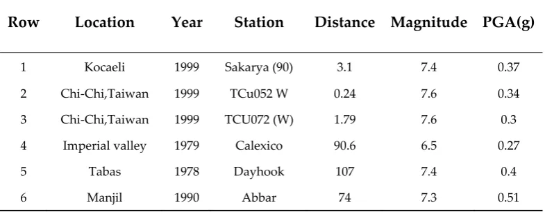
Used records in this research have been extracted from Earthquake Engineering Research Center at UC Berkeley [12]. Selected records include 6 earthquake records that three of them are related to near fault fields and the other three are related to far fault fields. These records are also recorded on soil equivalent for mentioned II soil in Iran’s 2800 standard. II soil in Iran’s 2800 standard is equivalent for soil type B from category USGS. All these accelerograms are coordinated based on maximum effective acceleration to plan basis acceleration to provide the possibility of comparing the results of analyzing frames under the effect of these recorders and the combination of these results is possible. The characteristics of select d records related to near and far fault fields are respectively shown in table 6.
Table 6. Earthquake mapping of near field and far-fault
Row Location Year Station Distance Magnitude PGA(g)
1 Kocaeli 1999 Sakarya (90) 3.1 7.4 0.37
2 Chi-Chi,Taiwan 1999 TCu052 W 0.24 7.6 0.34
3 Chi-Chi,Taiwan 1999 TCU072 (W) 1.79 7.6 0.3
4 Imperial valley 1979 Calexico 90.6 6.5 0.27
5 Tabas 1978 Dayhook 107 7.4 0.4
6 Manjil 1990 Abbar 74 7.3 0.51
As following two samples of acceleration time history graphs related to near and far fault fields are shown. The difference between near and far fault fields records can be seen in these records. Near fault field earthquake characteristics include: transmitting energy to structure in short time, the existence of pulse movement in beginning of the record and strike effect. These characteristics can be seen in figure 5- A.
9 of 15
(A)
(B)
Figure 5. Earthquake records (A) near field ChiChi052, (B) far field Imperial Valley
4. Non-linear time history dynamic analysis method
In this method, dynamic analysis of structure will be done by giving effect of the acceleration of the earth as a function of time in the base level of the structure and using structures’ dynamic common calculations. Non-linear time history dynamic analysis (moment to moment calculation of building’s reflections under the effect of earthquake real accelerograms) can be used for most of structures. Structure is analyzed in this method under the effect of several recorder accelerograms. Accelerograms should be in accordance with tectonic and geologic characteristics and their compatibility should be provided based on case, with maximum plan spectrum or earthquake spectrum. By non-linear phrases, we mean structure analysis considering its members’ non-linear behavior because of material non-linear behavior, fraction and etc.
Analysis is done by summing up or gradual integration during the time using stable average accelerates method. This case is also known as the trapezoid or Newmark method β=1/4. In this analytical method, time step of integration should be identified. The number of steps is equal to whole time divided by the time of each step unless analysis finishes before earthquake ending. In non-linear time history dynamic analysis for modeling non-linear behavior of structures, three linear non-linear joints have been used. The characteristics of these joints are based on “seismic rehabilitation of existing buildings instructions”. As following, the obtained results from non-linear time history dynamic analysis will be proposed.
4.1 Stories relative displacement graphs
In this section, graphs related to relative lateral displacement of mentioned models under the near field records are first proposed and then graphs related to far field have been shown.
10 of 15
As it can be seen in figures 6 till 8, under the effect of near fault earthquakes, the mot values of relative displacements will be obtained under the record of ChiChi052. Considering obtained relative displacements values, it is seen that assuming equal designing method, the results of all 4 mentioned
11 of 15
frames are near to each other. Among mentioned models, models of cx, cv, ev and ed have respectively the least values of relative displacements.
Among far field records also the most values refer to Imperial Valley. Under the effect of far field earthquakes, models with divergent bracings compared to other models have shown more predictable behavior. The least values of relative displacements refer to respectively models of cv, ev, cx and ed.
4.2 The graphs of stories lateral displacements
By paying attention to maximum graphs of lateral displacements , it was seen than most changes of lateral displacements are obtained under the effect of near and far fields to fault under the effect of respectively ChiChi052 and Imperial Valley. In lateral displacement graphs, models of cv, cx, ev and ed have respectively the least values under the effect of near and far fields.
12 of 15
4.3 Shear graphs
According to stories shear graphs, it is seen that under the effect of fault’s near and far fields, most shear values are created respectively in models of ed, cx, ev and cv that these most values are related to record ChiChi052.
Under the effect of far field records, difference of values of shear for model ed with other models, is more and this model continuously produces the most values of base shear values and after that models with bracings ev, cx and cv create respectively most values of base shear.
13 of 15
4.4 The results of energy graphs
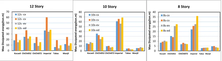
As following the rate of wasting entry energy derived from applied records in study frames will be investigated. This case is shown in figures 25 to 28. In these figures each one of colors represents a particular kind of waste energy in structure. The relationship between energy and its representing color can be seen in figure 24. As it is seen in figure 29, the most values of waste energy among near and far fields are respectively related to records Imperial Valley and ChiChi052 except 12 story models, in other models the most waste of energy happens in models with divergent bracing having joint beam.
Figure 24. Introducing the different kinds of energy waste and related colors
14 of 15
As it is seen under the effect of near field records, strain energy has allocated higher levels of waste energy to itself while under the effect of far field, waste strain energy has been reduced and viscos waste energy Alpha-M increases. In energy graphs under the effect of near fields, the effect of pulse kind strikes can be seen in beginning of record in a way that under the effect of these strikes, waste energy will reach to its most rate in structure. Among models with convergent bracings, model cv, and among models with divergent bracings model ed have wasted more values of energy through created strains in members while in models cx and ev most energy is wasted through viscose behavior Beta-K and this behavior can be seen in both near and far fields.
Figure 29. Maximum values of wasted energy in study frames
5. Conclusion
1- In dual steel frames, structures under the effect of near earthquake records to fault compared to structures under the effect of other records show different behavior. Although numerical results which have been obtained in this research depend completely on the characteristics of designed frames and records and other factors such as construction conditions but this result that structures have different behavior under the effect of these records can be generally accepted.
2- In dual steel frames the most values of relative displacement happens under the effect of near fields records in higher floors and under the effect of far field in middle floors. With increasing Tp/T in these models, the rate of participation and the effect of higher moods will
be more in structure response.
3- In dual steel frames, the values of relative displacement in models with convergent bracings are less than similar values in models with divergent ones in a stable designing process.
4- In dual steel frames, the values of base shear obtained from non-linear time history dynamic analyses are more for near field records than far field ones so it seems that in static analyses of frames near fault, shear values should be considered with higher bases.
5- In dual steel frames, share of column from floor shear in models having divergent bracing is more than models with convergent bracing. This case can be because of less lateral hardness than divergent bracings and their more formability.
6- In dual steel frames, during an equal process, obtained sections from designing for models having divergent bracing are bigger than models with convergent bracing.
0 10 20 30 40 50 60 70 M ax Dissipa te d en er gy (ton.m )
Kocaeli ChiChi052 ChiChi072 Imperial Tabas Manjil
12 Story 12s -cx 12s -cv 12s -ev 12s -ed 0 10 20 30 40 50 60 70 80 M ax Dissipa te d en er gy (ton.m )
Kocaeli ChiChi052 ChiChi072 Imperial Tabas Manjil
10 Story 10s-cx 10s-cv 10s-ev 10s-ed 0 5 10 15 20 25 30 35 40 M ax Dissipa te d en er gy (ton.m )
Kocaeli ChiChi052 ChiChi072 Imperial Tabas Manjil
8 Story
8s-cx 8s-cv 8s-ev 8s-ed
15 of 15
7- Relative lateral displacement of steel frames models having dual systems that are designed based on Iran’s 2800 standard in most situations are accepted by regulations. This case shows that this system has an appropriate performance.
8- In dual steel frames, depending on the kind of used bracing in them, the behavior of energy waste and the kind of waste energy is different. In models of cv and ev more energy through viscos process Beta-K and in models cv and ed more energy is wasted through created strains.
References
[1] Somerville PI.; "Effect of near field earthquake shaking"; Characterized of near fault ground motions; U.S.-Japan workshop; PEER and ATCI; 2000.
[2] Tirca L.D., Foti D., Diaferio M.;"Response of middle-rise steel frames with and without passive dampers to near-field ground motions"; EngineeringStructures; Vol.25, 2003, pp.169-179.
[3] Mollaioli, F. and Decanini, L. D. (2006). “Characterization of the dynamic response of structures to damaging pulse-type near-fault ground motions.” Meccanica , Vol.41, PP. 23-46.
[4] Kalkan, E. and Kunnath, S. K. (2006). “Effects of fling step and forward directivity on seismic response of buildings” Earthquake Spectra , Vol. 22, PP. 367-390.
[5] Miranda, E. and Akkar, S. (2006). “Generalized interstory drift spectrum.” J. of Structural Div., ASCE, Vol.132, No. 6, PP. 840-852.
[6]The regulation of planning buildings against earthquake (Iran’s 2800 standard), verison 3, the institution of Iran’s industrial and standard researches, 2005
[7] Tenth chapter of national regulations of construction (planning and performing steel construction), the ministry of Housing and Urban Development, 2008
[8] Graham, P. (2010). PERFORM-3D ver 5. Computer and Structure Inc.
[9] UBC 1997, Uniform Building Code, Volume 2 , Structure Engineering Design Provision.
[10] Computer and Structure Inc., ETABS. Linear and nonlinear static and dynamic analysis and design of building systems, Computer and Structure Inc., Berkeley, Calif, 2004.
[11] FEMA 356 (2000). Prestandard and Commentary for the Seismic Rehabilitation of Buildings, AmericanSociety of Civil Engineering for Federal Emergency Management Agency, Washington, DC.
[12] Pacific Earthquake Engineering Research Center (PEER), 2009, Peer New Generation of Attenuation (NGA) Records, Pacific Earthquake Engineering Research Center, University of California, Berkeley. Berkeley, CA.
© 2016 by the authors; licensee Preprints, Basel, Switzerland. This article is an open access article distributed under the terms and conditions of the Creative Commons by Attribution (CC-BY) license (http://creativecommons.org/licenses/by/4.0/).