A STUDY OF THE DESIGN OF FLUIDIZED
BED REACTORS FOR BIOMASS
GAS IFICATION
UC]L
I I
Ajmal LatifMEng.
A Thesis Submitted for the Degree of DOCTOR OF PHILOSOPHY at the University of London
November 1999
Department of Chemical Engineering Torrington Place
ABSTRACT
The present study is in two parts, the first part describes an investigation that was undertaken to determine the feasibility and hydrodynamic behaviour of a cold model circulating fluidized bed system proposed for the continuous combustion-gasification of biomass. The design is based on the principle that the char produced in the gasifier is circulated with the bed material and combusted in a separate reactor to generate the heat required for the gasification process. While high solid circulation rates are required to maintain the heat balance, product and flue gas mixing between the two units must be minimised or eliminated. The design of the circulating bed simply consists of two fluid bed units connected two together via a riser and a downcomer fitted with a non-mechanical valve. Various aspects such as solid circulation rate, gas mixing, solids mixing, and pressure component around the circulating ioop were studied.
Results show that the solid circulation and gas mixing are strongly influenced by the riser gas velocity, total solids inventory, and position of the riser from the riser gas jet. Solid circulation fluxes of up to 1 l5kg/m 2s were attained and easily controlled. The flue gas cross-flow was less than 4% over the range studied. By analysing the experimental data, a series of mathematical correlations were obtained which successfully predict the exponential relationship that exists between the solid circulation rate, gas mixing and the operating parameters. The potential of this system for its purpose is highlighted.
The second part of the study focuses on the design and development of a heated fluidized bed reactor with an on-line gas and solids sampling technique to study the steam gasification of biomass (almond shells). Experiments were conducted at temperatures of up to 800°C to investigate the gasification rates of biomass char under different operating conditions. Understanding the gasification and combustion rates of biomass char is an important step towards the proper designing of biomass gasifiers.
ii
ACKNOWLEDGEMENTS
I would like to express my most sincere gratitude to the following
Professor John G. Yates for his kind, invaluable and expert supervision and continuous encouragement during the ups and downs of this research and the write up. Although serving as head of department, his guidance and advice was always easy to find...I shall always be in debt.
Martin Town, Alan Craig, and Barry Bartram from the Mechanical Workshop and Martin Vale, Sarah Bailey and Mark Spurgeon from the Electronics Workshop for constructing the experimental apparatus.
Sam Okagbue, Julian Perfect and Dave Cheesman for their technical support. Anna Harrington, Paty Markey, and Sam Buckley for their administrative work.
My fellow research friends, Paola Lettieri, Ketan Patel, Raif Kehlenbeck, Xavier Pipen, and Damiano Rossetti, for their interest and friendship.
My mother and to name just a few of my numerous cousins, Marsilla, Zabrina, and Zia, for their love and support.
My uncle, Professsor S.S. Hashimi for his moral support.
111
7a- my ccw' nt7w cd'
Contents iv
TABLE OF CONTENTS
Abstract 1
Acknowledgements II
Dedication III
Contents Iv
List of Figures XI
List of Tables Xv
1 INTRODUCTION 1
1.1 Conclusions 6
1.2 Motivation and Objectives 7
1.3 Layout of Thesis 8
2 ENERGY FROM BIOMASS 9
2.1 What is Biomass? 11
2.2 The Main Processing Routes 12
Contents v
2.4 Thermochemical Conversion of Biomass 15
2.5 Gasification 18
2.5.1 Principles of Gasification 19
2.6 Product Gas Contaminants 19
2.7 Tar cracking 20
2.8 Catalytic Cracking 21
2.9 Thermal Cracking 22
2.10 Tar Removal 22
2.11 Char Gasification Kinetics 23
2.12 Sulphur 25
2.13 Biomass Gasification Technology 26
2.13.1 Fluid Bed Gasifier 26
2.13.1.1 Circulating Fluidized Bed 28
2.13.1.2 Pressurised Fluidized Bed 28
2.13.2 Down-Draft Gasifier 29
2.13.3 Entrained Bed Gasifier 30
2.13.4 Fixed Bed Updraft Gasifier 30
2.13.5 Choice of Gasifier 31
2.14 Biomass Feeding 31
2.15 Temperature and Pressure Effects 32
2.16 Biomass to Power Generation 32
2.17 What Are Fuel Cells? 34
Contents
2.17.2 Solid oxide fuel Cell 35
2.17.3 Solid Polymer Fuel Cells 35
2.17.4 Molten Carbonate Fuel Cells 35
2.17.5 Phosphoric Acid Fuel Cells 36
2.18 Conclusions 36
3 CIRCULATING FLU1DIZED BEDS 38
3.1 Solids Circulation Rate 42
3.2 Gas Mixing 43
3.3 Solids Residence Time 43
3.4 Conclusions 44
4 DESIGN OF EXPERIMENTAL EQUIPMENT 45
4.1 Description of the Circulating Fluidized Bed and Pilot Plant 45 4.2 Design of the Cold Model Dual Bed Circulating System 50
4.3 Windbox Design 50
4.3.1 Bed 1 And Windbox Design 51
4.3.2 Bed 2 and Windbox Design 55
4.4 Gas Distributor Plate 58
4.4.1 Design Criteria 58
4.4.2 Porous Distributor Plate Design 59
4.4.2.1 Design of bed 1 distributor 60
Contents 'ii
4.4.3 Sealing of the distributor 63
4.5 Particulate Filter 64
4.6 Non-Mechanical Valves 65
4.6.1 Aeration Tap Location 66
4.6.2 Design of L-valve Horizontal Length 67
4.7 Design of Solids Sampling Port 68
4.8 Design of the Heated Fluidized Bed Reactor System 69
4.9 Biomass Feeder Design 69
4.10 Sand Feeder 71
4.11 Feeder Probe Design 71
4.12 Fluidized Bed Cover Plate 75
4.13 Heated Windbox Design 76
4.14 Flexible High Temperature Hose 78
4.15 Gas Meter 78
4.16 Thermocouples 78
4.17 Pumps, Piping and Gas Supply 81
4.18 Cold Gas Filter 81
5 EXPERIMENTATION METHODS 82
5.1.1 Bed Inventory 84
5.1.2 Pressure Drop Experiments 84
5.1.3 Solid Circulation Rate Experiments 85
Contents viii
5.1.5 Solid Residence Time Experiments 86
5.1.6 Gasifier (bed 2) set-up 86
5.2 Heated Fluidized Bed Gasifler 88
5.2.1 Material (Biomass) Preparation 88
5.2.2 Bed Inventory 89
5.2.3 Gasification Pilot Plant Description 90
5.2.4 Gasification Procedure 93
5.2.4.1 Start-up 93
5.2.4.2 Biomass Gasification 93
5.2.5 Char/Steam Gasification and Sampling 94
5.2.5.1 Char Sampling System 95
5.2.5.2 Char Elimination 96
5.2.5.3 Char Analysis 96
5.3 Gasification Plant Photos 96
6 RESULTS AND DISCUSSION: COLD MODEL CIRCULATING FLUIDIZED
BED 100
6.1 Preliminary Results 100
6.2 Visual observations 103
6.2.1 Static 105
6.3 Solid circulation 105
6.3.1 Conclusions 115
Contents x
6.4.1 Conclusions 122
6.5 Relationship Between Solids Circulation and Gas cross-flow 122 6.6 Correlation of Solid Circulation and Gas Cross-flow 123
6.7 Solid Residence Time In Beds 129
6.8 Pressure Analysis 134
7 RESULTS AND DISCUSSION: HEATED FLUIIMZED BED GASIFIER 141
7.1 Segregation Along the Bed Axis 141
7.2 Bed Sampling Technique 143
7.3 Steady State Run Time 145
7.4 Gaseous Products and Composition 146
7.5 Carbon Conversion 149
7.6 Char Gasification Kinetics 150
7.7 Determination of the Char Gasification Rate Constant, k 156
7.8 Effect of Temperature 160
7.9 Determination of Optimum Gasifier Volume 161
7.9.1 Determination of Optimum Combustor Volume 163
7.10 Char Analysis 164
7.11 Conclusions 166
Contents x
9 FURTHER WORK 171
9.1 Scaling of Fluidized Beds 171
9.1.1 Preliminary Results 173
9.2 Circulating Fluidized Bed 175
9.3 Heated Fluidized Bed Gasifier 175
NOTATION 176
REFERENCES 180
APPENDICES
194 198 201 203 210 213 214 215 216 Appendix A:
Appendix B: Appendix C: Appendix D: Appendix E: Appendix F: Appendix G: Appendix H: Appendix I:
Sand and biomass feeder calibration Gas chromatograph calibration Water injection pump calibration
Size distribution and U,,f evaluation of experimental materials Density evaluation of experimental materials
Char density evaluation
List of Figures x
List of Figures
Fig. 1.1 Flow patterns in gas solid fluidized beds (Grace, 1986). 2
Fig. 1.2 Typical circulating fluidized bed system. 3
Fig. 2.1 Typical molecular structures of biomass and coal (Hedley and Bustani, 1989) 11
Fig. 2.2 Alternative Biomass Degradation Routes. 12
Fig. 2.3 Simplified biomass pyrolysis reaction (Diebold, 1994). 18 Fig. 2.4 Main gasifier types (Kurkela Ct al., 1993). 26 Fig. 2.5 Typical product gas composition for the steam gasification of biomass. 27 Fig. 2.6 Product gas composition as a fUnction of gasifier pressure. 29 Fig. 2.7 Biomass energy conversion using pyrolysis and gasification. 33 Fig. 3.1 Schematic diagram of the circulating fluidized bed system. 39 Fig. 3.2 Pilot plant circulating fluidized bed gasifier-combustor. 41 Fig. 3.3 Side view of the oil shale retort circulating fluidized bed (Chong et aL, 1986) 42 Fig. 4.1 Configuration of the circulating fiuidized bed system. 46 Fig. 4.2 Principle of biomass combustion-gasification process. 47 Fig. 4.3 Flow sheet of the biomass combustion - gasification plant. 49 Fig. 4.4 Schematics and dimensions of windbox for bed 1 (not to scale). 53
Fig. 4.5 Bed 1 dimensions (not to scale). 54
Fig. 4.6 Schematics and dimensions of windbox for bed 2 (not to scale). 56
Fig. 4.7 Dimensions of bed 2 (not to scale). 57
87 91
List of Figures xii
Fig. 4.15 Schematic diagram of the sand feed. 73
Fig. 4.16 Biomass feeder probe. 74
Fig. 4.17 Schematic diagram of the stainless steel bed cover. 75
Fig. 4.18 Schematics of the heated windbox. 79
Fig. 4.19 Schematics of the high temperature flexible tubing. 80 Fig. 5.1 Schematic diagram of the cold bed experimental set up. 83 Fig. 5.2 Schematic diagram of the cold model circulating fluidized bed corresponding to
Mark 1.
Fig. 5.3 Schematics of the biomass / char gasification pilot plant set-up. Fig. 6.1 Solid circulation rate versus riser superficial gas velocity for Mark 1. Fig. 6.2 Gas cross-flow versus riser superficial gas velocity for Mark 1. Fig. 6.3 Solid circulation rate versus riser gas velocity for bed for Mark 2. Fig. 6.4 Gas and solids flow in the L-valve.
Fig. 6.5 Tracer particle with metal inclusion. Fig. 6.6 Solids flow through the L-valve.
Fig. 6.7 Solid circulation flux versus riser superficial gas velocity. Fig. 6.8 Solid circulation flux versus riser superficial gas velocity. Fig. 6.9 Solid circulation flux versus riser superficial gas velocity. Fig. 6.10 Solid circulation flux versus riser superficial gas velocity. Fig. 6.11 Solid circulation flux versus riser superficial gas velocity. Fig. 6.12 Solid circulation flux versus riser superficial gas velocity. Fig. 6.13 Plot of GJU, versus riser superficial gas velocity, Ur. Fig. 6.14 Solid circulation flux versus riser superficial gas velocity. Fig. 6.15 Solid circulation flux versus riser superficial gas velocity. Fig. 6.16 Solid circulation flux versus riser superficial gas velocity.
Fig. 6.17 Solid circulation flux as a function of riser superficial gas velocity Fig. 6.18 Solid circulation flux as a function of riser superficial gas velocity Fig. 6.19 Solid circulation flux as a function of riser superficial gas velocity Fig. 6.20 Solid circulation flux as a function of riser superficial gas velocity Fig. 6.21 Critical riser superficial gas velocity, U, as a function of X1.
List of Figures xiii
Fig. 6.22 Gas cross-flow versus U1 for bed load 12kg. 117 Fig. 6.23 Gas cross-flow versus U1 for bed load 17kg. 118 Fig. 6.24 Gas cross-flow versus U1 for bed load 22kg. 118 Fig. 6.25 Gas cross-flow versus U1 for X. = 1.0cm. 119 Fig. 6.26 Gas cross-flow versus U1 for X1 = 2.5cm. 120 Fig. 6.27 Gas cross-flow versus U1 for X1 = 4.0cm. 120 Fig. 6.28 Relationship between the gas cross-flow and X1. 121
Fig. 6.29 Gas - solid flow at the riser inlet. 122
Fig. 6.30 Relationship between solid circulation and gas cross-flow. 123 Fig. 6.31 Dimensionless gas cross-flow vs. dimensionless riser gas velocity 124
Fig. 6.32 K 1 - 1(4 values as a function of. 126
List of Figures xiv
Fig. 7.2 Effect of gas velocity on the segregation of char in the bed. 143 Fig. 7.3 Effect of Oxygen leakage on the accuracy of the sampLing technique. 144 Fig. 7.4 Reproducibility of the sampling technique; weight percent of char. 145
Fig. 7.5 Steady state dry gas composition. 146
Fig. 7.6 Dry gas composition at steady state. 147
Fig. 7.7 Trace species composition in the dry gas. 147 Fig. 7.8 Total gas yield as a function of temperature. 148 Fig. 7.9 Char and tar (approx.) yield as a function of temperature. 149 Fig. 7.10 Carbon conversion as a function of temperature. 150 Fig. 7.11 Mass of char remaining in the bed as a function of gasification time. 151 Fig. 7.12 Effect of gasification temperature on char conversion. 154 Fig. 7.13 Experimental char gasification rate constant, lc. 159 Fig. 7.14 Surfaces of chars formed as function of gasification temperature and residence
time in the gasifier. 165
List of Tables xv
List of Tables
Table 1.1 Applications of fluidized bed reactors. 2
Table 2.1 Typical composition of coals a (% by weight, moisture free basis). 13 Table 2.2 Typical composition of biomass a (% by weight, moisture free basis). 14 Table 2.3 Manufactured fijels a (% by weight, moisture free basis). 14 Table 2.4 Basic reactions in gasification of carbonaceous materials. 17 Table 2.5 Contaminants present in the gasifier product gas. 20 Table 2.6 Investigation of char gasification kinetics using various methods 24 Table 2.7 Typical char gasification kinetic models and references. 24 Table 2.8 Gasification rate constants for various chars. 25 Table 2.9 Product gas composition and yield from pine wood chip gasification. 34 Table 4.1 Stream table for the fluidized bed gasifier. 48
Table 4.2 Gas meter flow rate errors. 78
Table 5.1 Physical and Flow Properties of the Silver Sand. 84
Table 5.2 Composition of the Almond Shells. 89
Table 5.3 Size Distribution of the Almond Shells. 89
Table 5.4 Physical Properties of the Silver Sand. 89
Table 7 1 Char complete conversion times at various temperatures. 154
Table 7.2 k values as function of temperature. 156
Table 7.3 Comparison of k and lc values. 158
Chapter 1 - Introduction i
Chopte4 1
1 INTRODUCTION
Chapter 1 - Introduction 2
Fig. 1.1 Flow patterns in gas solid fluidized beds (Grace, 1986).
Table 1.1 Applications of fluidized bed reactors.
Fluidized bed application Reference
Combustion and incineration (Wang and Lin, 1998)
Carbonisation and gasification (Schrader and Felgener, 1978)
Sohio Process (Acrylonitrile Production)
I
(Kunii and Levenspiel, 1991) Synthesis reactionsFischer-Tropsch (Silverman et a!., 1986)
Biofluidization
Cultivation of Micro-organisms (Schuegerl, 1989)
The ability to maintain a stable and continuous circulation of solids in a gas-solid system has led to the development of the Circulating Fluidized Bed (CFB) for a number of processes, usually large-scale operations, especially in the petroleum industry and power generation. Circulating fluidized beds work in much the same way as bubbling beds but with one major difference. The velocity of the fluid flow is much greater so that there is a more intense mixing of the fluid with the particles in the bed providing excellent gas-solid
Aeration
Chapter 1 - Introduction 3
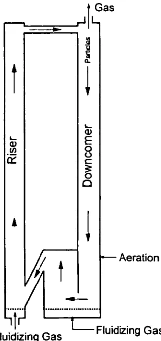
contact. Also the high relative velocity between the gas and solid particles results in very high rates of heat and mass transfer. However, the high gas velocities and the recirculation of solids may make the CFB system more expensive in terms of power requirement and investment compared with conventional fluidized bed reactors (Bridgwater, 1995). A typical configuration of a CFB is shown in Fig. 1.2. The high gas velocity in the riser (3-16 mIs) carries the particles (usually 0.05 to 0.5 mm) upwards where they are separated from the gas and returned to the bed via the downcomer. The solid circulation flux (typically 15 to
1000 kg/m2s) is controlled by the gas velocity in the riser and the aeration gas in the downcomer. The driving force for the solids circulation is the bulk density difference in different parts of the circulating system. Solids usually circulate from regions of high bulk density to region of lower bulk density.
f Gas
Fluidizing Gas Fluidizing Gas
Chapter 1 - Introduction 4
CFBs have been extensively used in the field of solid catalysed gas phase reactions in one of the following two situations. The first is where continuous regeneration of a catalyst that deactivates rapidly is required. In this situation, a steady circulation of solids is maintained where the catalyst is continuously regenerated and returned to the reactor. A second set-up is where heat must be brought into or removed from a reactor. Solids have a relatively large heat capacity as compared to gases and thus a continuous circulation of solids between two vessels can effectively transport heat from one vessel to another and control the temperatures in the units.
In recent years, much attention has been focused on the use of CFBs for the less dense forms of solid fuels such as biomass for the production of energy. The escalation of interest in this field has been partly due to the increasing price of oil and diminishing fossil fuel reserves and tighter control over the emission of greenhouse gases such as carbon dioxide. Biomass is the ecological term for organic material, both above and below the ground and both living and dead, such as trees, crops, grass, tree litter and roots. The types of biomass used in energy production include energy crops like willows and aspen poplar, wood and wood wastes, agricultural and agro-industrial wastes, sewage sludge and municipal wastes. The use of biomass for the production of energy is a carbon dioxide neutral cycle, only releasing the carbon dioxide that it has taken up during growth, since biomass is formed from photosynthesis, a process that converts carbon dioxide and water into oxygen and organic matter. Biomass accounts for nearly 15% of the world energy supplies (Wereko-Brobby and Hagen, 1996). In industrialised countries, biomass fuel supplies about 3% of the total primary energy compared to 35% in developing countries.
The thermochemical conversion of these fuels into heat and power involves one of three processes, direct combustion, pyrolysis, and gasification, for which any sufficient dry combustible material can be used. Combustion involves direct burning to produce heat, which in power generation is applied to boilers to produce steam in order to drive turbines.
Chapter 1 - Introduction 5 varying proportions of the solid char, oil and gas. Thermochemical gasification is the conversion by partial oxidation at elevated temperature of a carbonaceous feedstock such as coal or biomass into a gaseous energy carrier. This contains carbon monoxide, carbon dioxide, hydrogen, methane, trace amounts of higher hydrocarbons such as ethene and ethane, water, nitrogen (if air is used as the oxidising agent) and various contaminants such as small char particles, ash, tars, and oils. The tars constitute only a small proportion of the biogas but can cause considerable problems (e.g., equipment fouling) during the gas downstream use. The partial oxidation can be carried out using air, oxygen, steam, or a mixture of these.
Air gasification produces a poor quality gas in terms of heating values (4-7 MJm3 higher heating value) which is suitable for boiler, engine and turbine operation, but not for pipeline transportation due to its low energy density. Oxygen or steam gasification produces a better quality gas (10-18 MJm 3 higher heating value) which is suitable for limited pipeline distribution and for use as synthesis gas with the process energy supplied via the combustion of the by-product char in a separate reactor.
Biomass gasification is a highly endothermic process requiring large quantities of heat (see Table 2.4). The heat can be supplied to the gasifier via an independent and external source, so-called 'direct' heating or by circulating an inert bed material between a gasification and a combustion zone, 'indirect' heating. Although the first arrangement has the advantage of physically separating the gasifier from the source of heat and utilising spare energy from processes that might otherwise be wasted, the inevitable drawback is that it is attached to other heat generating processes and requires large surface areas for the heat transfer. Indirect heating produces a gas with consistent heating values regardless of the feedstock's moisture content, however, care must be taken in order to minimise product gas contamination.
Chapter 1 - Introduction 6
useful energy. For woody biomass resources it is the moisture content of the wood rather than the particular species, that determines the available energy. There are two important determinants of the energy value of non-woody plant biomass, one is the moisture content and the other is the ash content. While the ash content of most wood is constant at about 1%, that of crop residues can vary from about 1 % to 20%.
The use of biogas together with fuel cells for the production of electric power in rural areas has the potential for widespread development. Fuel cells are electrochemical devices that convert the energy of a chemical reaction directly into electricity and heat. Unlike primary batteries, fuel cells store the fuel and oxidant externally, allowing continuous operation. While the reaction that drives all fuel cells involves hydrogen, pure hydrogen is currently too expensive to produce and transport in bulk. The current alternative is to process fuels, such as biomass in order to produce hydrogen and to feed this, after suitable gas cleaning, directly to the fuel cell.
Fuel cells can convert up to 60% of the total energy stored in a fuel into electricity. Reusing the heat released during the process allows efficiencies of up to 85% to 90% to be achieved. This makes fuel cells much more attractive than gas turbines and internal combustion engines, which are unable to achieve electrical efficiencies much above 40% and combined electrical and thermal efficiencies much above 60%. However, at present fuel cell units are very expensive and still under development.
1.1 CoNcLusioNs
Chapter 1 - Introduction 7
As environmental concerns become increasingly important, it will no longer be just a simple case of power generation, but rather a balance between increased efficiency and reduced environmental impacts with low costs and risks. The diversity and ready availability of biomass along with existing and developing technologies make biomass a strong alternative to fossil fuels for future energy requirements around the world. This allows developing and industrialised countries the ability of producing bioenergy without significant structural changes in the industries.
1.2 MoTIvATIoN AND
OBJECTIVES
The objective of the present work was to study processes for the gasification of biomass in fluidized beds.
The first part investigates the hydrodynamic behaviour of a cold model circulating fluidized bed proposed for the continuous combustion-gasification of biomass. The design is based on the principle that the char produced in the gasifier is circulated with the bed material and combusted in a different reactor to generate the heat required for the gasification process. While high solid circulation rates are required to maintain the balance, product and flue gas mixing between the two units must be minimised or eliminated. Various aspects such as solid circulation rate, gas mixing, solid mixing, and pressure profile around the circulating loop were studied.
Chapter 1 - Introduction 8
analyser to obtain char gasification kinetics. It is hoped that the present work extends the knowledge of char gasification kinetics by examining bed samples withdrawn at operating conditions.
1.3 LAYOUT OF THESIS
Chapter 2 - Energy from Biomass 9
C1wtptev 2
2 ENERGY FROM BIOMAss
The deterioration in the supply of conventional fuels, and the problems of climatic changes, have led to a resurgence in research and development studies investigating alternative solid fuel supplies. Thus, increasing attention is given to studies of processes involving the conversion of biomass and related products to gaseous fuels. Gasification of biomass as a source of hydrogen and other valuable gases seems to be the best route for converting it to an energy vector. This can be used in a wide range of applications, for example, in fuel cells for the production of electricity.
The formation of hydrogen from biomass is a recycle process without a net increase of carbon dioxide level or depletion of natural resource, since biomass arises from the photosynthesis of carbon dioxide and water. Further more, most biomass contains less sulphur than fossil fuels, and would be expected to provide an economical advantage in the cleaning of sulphur compounds.
Experimental investigations of biomass gasification (Corella et al., 1991) have shown that the first step in this process is the pyrolysis or devolatilisation of the biomass particles, as a result of which volatile matter and char are produced. This is followed by secondary reactions, involving cracking and reforming of the evolved volatiles and gasification of char. According to this reaction scheme, when the object is the production of organic liquids, the operating temperature should be kept at relatively low values, whereas high operating temperatures and a steam atmosphere maximises the gas yield.
Chapter 2 - Energy from Biomass 10
1976; Hajaligol et al., 1980), vacuum reactor (Bradbury et a!., 1979), fluidized bed reactors (Barooah and Long, 1976; Kosstrin, 1980; Liden et al., 1988; Scott et a!., 1988; Rapagna et al., 1992), fixed bed reactor (Chatzakis et al., 1995), etc. Also a wide diversity of materials (cellulose, lignin, wood and other types of biomass), with different operating conditions are used. In recent years a considerable number of books and papers have appeared about the gasification and pyrolysis of biomass in fluidized beds. The results obtained by different authors are quite different from one another, due to the numerous factors which influence the product distribution obtained. For this reason the comparison of these results with one another is usually rather difficult. In pyrolysis and gasification in fluidized beds, the product distribution depends on at least the following factors:
1. Gasifying agent (steam, air, steam and oxygen, nitrogen, etc.) 2. Type of biomass used
3. Moisture and size of particle
4. Temperature and pressure in the gasifier 5. Gasifying agent to biomass ratio
6. Presence or not of primary catalysts 7. Amount of char in the bed
8. Superficial gas velocity of the gasifying medium 9. Type, size, and weight of bed particles
There are many more such factors that have a direct or indirect effect on the product distribution.
Chapter 2 - Energy from Biomass 11
2.1 WHAT IS BIOMASS?
Biomass is a term given to any kind of carbonaceous material (wood and agricultural) that has the potential to be converted into useful energy via the appropriate technology. It is a renewable resource occurring naturally and repeatedly in the environment. As a result, the proportions of the basic constituents and the overall morphological characteristics of any biomass are specific to its location.
Biomass occurs mainly in a solid form, which is obtainable from sources such as plant tissue, wood, urban refuse, or any other renewable form of organic material which can be produced or made available, after relatively short periods of time. A typical molecular structure of biomass and coal are shown in Fig. 2.1 and by contrast, the molecular structure of biomass is relatively simple, however, the structures of some of the major organic components in biomass are shown on the left of Fig. 2.1 (Klass, 1998). The average chemical formula for biomass has been reported as CH1.400.6N0.1
(Overend, 1998). Biomass material generally is more oxygenated, has a lower calorific value, and contains a greater amount of moisture than coal.
Chapter 2 - Energy from Biomass 12
2.2 THE MAIN PROCESSING ROUTES
When biomass is processed into a gaseous or liquid product, a degradation of its molecular structure takes place. The ability to totally convert a carbonaceous starting material depends largely on the extent of degradation that can be brought about, and in many cases complete conversion to a product gas or liquid is just impossible, at least in a single step. In general, there are five different routes available for the degradation of a solid carbonaceous material as can be seen from Fig. 2.2.
CH3
process -
tJIOJ
PhysaI______ is
Olive oil
OH
OCSS '
Coke. CH4
LJ
CH3coal or rnhemicai Tar
8 omass process - Charcoal. • Tar CO2
Biochemical
_____ -.-H-ç-OH H-C-f-OH CH4
process
H H
Alcohols or thane
.) Sl.I
H2. CH4.c02. H20
Fig. 2.2 Alternative Biomass Degradation Routes.
2.3 TYPES OF CARBONACEOUS MATERIAL AVAILABLE FOR GASIFICATION
Lists of some of the different more available types of carbonaceous material which can be gasified are presented in Table 2.1 for coals, in Table 2.2 for biomass, and in Table 2.3 for other manufactured fuels.
Chapter 2 - Energy from Biomass 13
cost of de-watering and drying operations can be prohibitive and could be the limiting factor for its economic use.
The ash content can vary widely
from type to type of coal or biomass, and from place to place of their origin.
The properties and behaviour of the ash, and its quantity, may be limiting factors in the choice of gasification system.
Table 2.1 Typical composition of coals a (% by weight, moisture free basis).
High volatile Medium
Peat Lignite coking volatile Anthracite material coking coke
Carbon 54.6 65.9 76.1 80.4 85.0
Hydrogen 5.20 4.70 4.80 4.50 2.60
Nitrogen + Sulphur 1.90 1.90 3.50 2.70 2.10
Oxygen 33.3 21.6 6.60 3.80 1.60
Ash 5.00 5.90 9.00 8.60 8.70
100 100 100 100 100
Moisture 20-60 10-50 0-20 0-20 0-15
Volatile matterb 68 53 36 25 6
Calorific valuec 12.0 17.7 26.2 27.5 30.4
(MJ/kg)
Chapter 2 - Energy from Biomass 14
Table 2.2 Typical composition of biomass a (% by weight, moisture free basis). Cellulose Wood Grass Municipal Animal Sewage
refuse Manure sludge
Carbon 44.4 51.8 45.8 41.2 35.1 43.8
Hydrogen 6.20 6.30 5.90 5.50 5.30 6.20
Nitrogen + Sulphur - 0.10 5.20 0.70 2.90 4.10
Oxygen 49.3 41.3 29.6 38.7 33.2 19.4
Ash - 0.50 13.5 13.9 23.5 26.5
100 100 100 100 100 100
Moisture - 5-50 10-70 18.4 20-70 90-97
Volatile matterb - 80 70 67 63 57
Calorific valueC
(MJ/kg) 17.5 15.4 11.2 10.4 7.40 1.30
asource: (Kirk-Othmer, 1980; Boyles, 1984), bMojsture and ash free, CGross, as received.
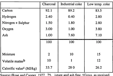
Table 2.3 Manufactured fuels a (% by weight, moisture free basis). Charcoal Industrial coke Low temp. coke
Carbon 92.1 89.2 83.5
Hydrogen 2.40 0.40 2.80
Nitrogen + Sulphur 1.50 1.80 2.80
Oxygen 3.00 1.00 3.80
Ash 1.00 7.60 7.10
100 100 100
Moisture 2 10 15
Volatile matterb 10 1 12
Chapter 2 - Energy from Biomass 15
2.4 THERMOCHEMICAL CONVERSION OF BIOMASS
Biomass is a source of non-fossil renewable fuel that can be used to replace oil and other hydrocarbon fuels. Biomass is widely considered to be a major potential fuel and renewable resource for the future. In terms of size of resource, there is the potential to produce at least 50% of Europe's total energy requirement, from purpose grown biomass using agricultural land no longer required for food, and from wastes and residues from agriculture, commerce and consumers (Grassi and Bridgwater, 1991; Grassi and Bridgwater, 1992). As produced, biomass is a solid and is difficult to use in many applications without substantial modification. Conversion to gaseous and liquid energy carriers has many advantages in handling and application. One of the major problems with biomass is that, as an energy crop, it is labour-intensive to produce, harvest and transport, as it is dispersed over large areas. When it is in the form of wastes, costs are much lower, often negative in the case of domestic solid wastes (Bridgwater and Evans, 1993), but the material usually requires extensive processing to make it compatible with the conversion process.
There are several conversion routes available such as thermal (combustion), thermochemical (gasification, pyrolysis) and biological (anaerobic digestion, fermentation to ethanol). At present thermal and thermochemical processes are more efficient and easier to operate since they result in almost complete conversion. Biomass combustion and char gasification are well understood, however, biomass pyrolysis is still not adequately known although it is the important first step in all thermal and thermochemical conversion processes.
Chapter 2 - Energy from Biomass 16
products at the expense of char and gas with vapour residence times of less than 2s. On the other hand, in fast pyrolysis extremely high heating rates (1,000 - 20,000°C/s) are used at temperatures higher than 600°C and very short vapour residence times (less than 0.5s) in order to produce gas at the expense of char and tar/oil (Graham et al., 1984). It has also been shown that the thermal properties, heat flux and pellet length interact in a non-linear way to alter the ultimate yields and instantaneous rate of gas production from a rapidly pyrolysing large pellet of biomass (Chan et al., 1985).
To further enhance the gaseous quality, steam has been used as an active medium. Steam gasification of cellulosic waste or of biomass in fluidised beds was studied in the early 1980's when it was thought this could be an alternative energy source. Nevertheless, the low price of oil and its derivatives, the disposal of cheap natural gas and healthy economies of the countries in the late 1980's meant that this process was not competitive as a source of energy. A lot of new developing technologies were stopped by the absence of continuing funds. Only a few new processes for biomass were commercialised such as the one at Studvik Energy in Sweden, but many pilot plants were dismantled without having solved all the technical problems. This was the case of steam gasification of cellulosic waste in a fluidized bed which can have a good future not only because of oil price increases, but also because it can eliminate solid waste with energy production by the generated gas.
The off-gases from the top of the gasifier at a temperature ranging from 600°C to 900°C and near atmospheric pressure typically contain water vapour, very small amounts of condensable organic oil, and non-condensable gases (Rapagna et al., 1992). The main components of the gaseous phase are hydrogen, carbon monoxide, methane, carbon dioxide, water vapour, and very small amounts of low molecular weight hydrocarbons. The volatiles, primarily produced from the biomass, then undergo reactions in the gaseous phase.
Chapter 2 - Energy from Biomass 17
temperature gasification of carbonaceous materials and these are presented in below in Table 2.4.
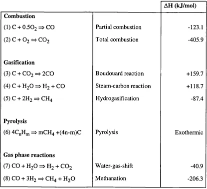
Table 2.4 Basic reactions in gasification of carbonaceous materials. H (kJ/mol) Combustion
(1) C + 0.502 = CO Partial combustion -123.1
(2) C + 02 = CO2 Total combustion -405.9
Gasification
(3) C + CO 2 = 2C0 Boudouard reaction + 159.7 (4) C + H20 H + CO Steam-carbon reaction +118.7
(5) C + 2H2 = CH4 Hydrogasification -87.4
Pyrolysis
(6) 4CnHm mCH +(4n-m)C Pyrolysis Exothermic
Gas phase reactions
(7) CO + H20 H2 + CO2 Water-gas-shift -40.9
(8) CO + 3H2 CH4 + H20 Methanation -206.3
The principal heterogeneous reactions of char with steam and volatiles are (Bungay, 1981):
C^ H 20 = CO + H2 C-i-2H 2 =CH4 Ci-0O 2 =2C0
Chapter 2 - Energy from Biomass 18
simplification of this complex reaction scheme is shown in Fig. 2.3 (Diebold, 1994). The overall process can be broadly classified into primary and secondary stages. The primary reactions are dependent only on the local solid temperature. When pyrolysis is carried out at high temperatures (above 700°C), the secondary reactions (especially tar cracking reactions) are progressively more important, involving gas-solid interactions and thus depend on the contact time distribution.
Fig. 2.3 Simplified biomass pyrolysis reaction (Diebold, 1994).
2.5
GAsIFIcATIoNThermochemical gasification involves the conversion of a carbonaceous feedstock such as biomass or coal at elevated temperature into a gaseous energy carrier. The gaseous product generally contains carbon monoxide, carbon dioxide, hydrogen, methane, trace amounts of higher hydrocarbons such as ethane and ethene, water, nitrogen (if air is used as the oxidising agent) and various contaminants such as small char particles, ash, tars and oils. The partial oxidation can be carried out in the presence of air, oxygen, steam or a mixture of these.
If air is used as the gasification medium, a poor-quality gas is produced in terms of heating value (4-7 MJm 3 higher heating value). This type of gas is suitable for boiler, engine and turbine operation, but not for pipeline transportation due to its low energy density. A better-quality gas is produced with oxygen (10-18 MJ m 3 higher heating value) which is suitable for limited pipeline distribution and for use as synthesis gas for conversion, for example, to methanol and gasoline. Gas of this quality can also be
Chapter 2 - Energy from Biomass 19
produced by steam gasification, with the process energy being supplied by combustion of by-product char in a second reactor.
2.5.1 PRINCIPLES OF GASIFICATION
Gasification occurs in different steps as listed below: • evaporation of moisture by drying,
• pyrolysis resulting in the production of gas, vaporised tars or oils and a solid char residue,
• gasification or partial oxidation of the solid char, tars and gases.
Subjecting a solid fuel to heated (35O5000C) in the absence of an oxidising agent, results in pyrolyses of the fuel to solid char, tar (condensable hydrocarbons), and gases. As mentioned before, the relative yields of gas, liquid and char depend on the rate of heating and the final temperature. Generally the pyrolysis or devolatillisation step is much more rapid than gasification, and consequently the latter is the rate-controlling step. The interaction and reaction of the gas, liquid and solid products of pyrolysis with the oxidising agent give permanent gases (CO, CO 2, H2,) and lesser quantities of hydrocarbon gases. Char gasification is the interactive combination of several gas-solid and gas-gas reactions in which solid carbon is oxidised to carbon monoxide and carbon dioxide, and hydrogen is generated through the water-gas shift reaction. The gas-solid reactions of char oxidation are the slowest and limit the overall rate of the gasification process. Many factors such as feed composition, water content, and reaction temperature influence the gas composition.
Due to the physical and geometrical limitations of the reactors and also the limitations imposed by the chemical reactions that take place, it is not possible to convert all of the liquid products generated in the pyrolysis stage. As a result, the product gas always contains contaminants in the form of tar.
2.6 PRODUCT GAS CONTAMINANTS
Chapter 2 - Energy from Biomass 20
of course on the type of gasifier and the feedstock fuel. An important step after the gasification process is the gas cleaning which is absolutely necessary in order to prevent erosion, corrosion of the downstream equipment and to minimise environmental impact. Table 2.5 gives a list of the some of the contaminants present in the product gas along with the problems associated with them and typical cleaning method.
Table 2.5 Contaminants present in the gasifier product gas (Bridgwater, 1995).
Contaminant Example Problems
Nitrogen NH3, HCN NO formation
Particulates Bed material, ash, char Erosion
Tars Aromatics, heavy deposits internally hydrocarbons, Blocks filters Alkali metals Sodium, Potassium Hot corrosion
Sulphur H2S Emissions
Chlorine HC1 Corrosion
2.7 TAR CRACKING
Cleaning method Scrubbing
Filtration, scrubbing See below Cooling, adsorption Dolomite scrubbing Wet scrubbing
Katheklakis et al. (1990) have investigated the effect of freeboard residence time (0.8 and 4.5 s) on the molecular mass distribution and yield of fluidized bed pyrolysis tars over the temperature range of 400 - 750 °C. The atmospheric pressure fluidized bed has a movable gas distributor plate which allows the variation of volatiles residence time without varying the fluidized bed conditions. The tars evolved were collected using a wire mesh screen. Significant tar loses were reported for a longer residence time at lower temperatures (500 °C) through covalent bond scission. This decrease has been accompanied with an increase in volatile production. Also the molecular mass fractions of the evolved tars were seen to decrease with increasing temperature, indicating that tar cracking to lower molecular masses becomes dominant.
Tar concentration is mainly a function of gasification temperature, the tar yield increases slightly with an increase in temperature, goes through a maximum (about
Chapter 2 - Energy from Biomass 21
temperature. Stiles and Kandiyoti (1989) have reported this maximum at much lower temperatures during the pyrolysis of lignite and several other biomass materials. The relation between temperature and tar level is a function of reactor type and processing conditions and feedstock.
Megaritis et a!., (1998) have reported that fluidized bed tar yields are lower than those obtained in a wire mesh cell over the same temperature range. They have attributed this to the longer residence time of solids (order of minutes) within the fluidized bed which allows for the completion of pyrolysis reactions. Tests have shown that tar production in wood gasification is much greater than in coal or peat gasification and that the tars tend to be heavier, more stable aromatics (Diebold et al., 1992). This may give rise to the formation of soot which can block filters, a problem common to biomass gasification. Therefore coal gasification tar cleaning technology may not be easily applied to biomass feeds. There are two basic ways of destroying tars:
• by catalytic cracking using, for example, dolomite or nickel (Narvaez et al., 1997; Olivares et al., 1997),
• by thermal cracking, for example by partial oxidation or direct thermal contact (Corella et al., 1998).
2.8 CATALYTIC CRACKING
Catalytic cracking of tars is highly effective and tar conversions in the range of 99% can be attained by using dolomite or nickel-based catalysts at temperatures of around 800-900 °C. These tests have been performed using both fossil and renewable feeds. Most investigations have made the use of a second reactor, however some work has been carried out on incorporation of the catalyst in the primary reactor (Rapagna and Foscolo, 1999), which has often been less successful than use of a second reactor (Corella et al., 1988). Elevated freeboard temperatures thermally crack tars and can reduce the load on the catalytic cracker.
Chapter 2 - Energy from Biomass 22
susceptible to contamination. Low hydrogen concentrations in the product gas reduce the catalytic activity of metal-based systems. The low sulphur content of biomass gases can reduce the activity of metal suiphide catalysts through stripping-out of the sulphur. The use of a circulating fluid bed technology offers some advantage in the regeneration of the catalyst in the combustion zone. Attempts to impregnate the catalyst on the surface of the inert bed material in a circulating bed has been promising but has failed in long run tests due to attrition problems (Rapagna and Foscolo, 1999).
2.9 THERMAL CRACKING
Tar levels can be reduced by thermal cracking at temperatures around 800-1000 °C (Diebold, 1994). However, the nature of the tars produced from biomass makes them harder to crack by thermal treatment alone as temperature increases. Although elevated freeboard temperatures in fluid bed gasifiers result in some thermal tar cracking, there are also other options available such as:
• increasing tar residence time in the fluid bed reactor freeboard.
• bringing the tars to direct contact with an independently heated hot surface, this method requires a significant energy supply and thus leads to a decrease in the overall efficiency.
• the addition of air or oxygen to partially oxidise the tars. Although this technique is very effective specially at gasification temperatures as high as 1300 °C, however, the consequences are that it increases CO2 levels, reduces efficiency and increases costs for oxygen use.
2.10 TAR REMOVAL
Chapter 2 - Energy from Biomass 23
Oil scrubbing has also been looked at, but the disadvantages are far greater than the benefits. Electrostatic precipitation is an effective but costly way of removing tars, but there is little experience on biomass-derived gasification products.
2.11 CHAR GASIFICATION KINETICS
In the case of continuous combustion-gasification of biomass in a circulating fluidized bed, the design of the gasifier should not be such as to have complete gasification of the feed material but, also to maintain efficient combustion by circulating some of carbonised material to the combustion section. To further improve the overall process efficiency and economics, gas production in the gasifier should be maximised. As a result, proper understanding of the gasification rate of char is of crucial importance in the successful design of biomass gasifiers.
As said earlier, biomass is decomposed to produce gaseous products and a residual char in the first step. The second step is the secondary reactions of the volatiles and the last step is the gasification of the residual char. The kinetics of the first step has been investigated by Koufopanos et al. (1991), however, the gasification rate of char (being the slow step) is sensed to be the most critical information required for optimum reactor design. The physical characteristics and hence the reactivity of the char have been found to vary with the history of its genesis, i.e., temperature, partial pressure of gasifying agent, rate of heating, gaseous environment, and particle size all play a part during its formation. Most kinetic measurements of char gasification has been investigated in thermo-gravimetric analysers (TGA) which are operated under conditions far from realistic and commercial equipment. The heat treatments under which the char is formed also affects the subsequent reactivity during the char gasification (Riley and Judd, 1987).
Chapter 2 - Energy from Biomass 24
result in a significant difference in reaction rate. Burnham (1979) studied the gasification rate of oil-shale using steam and carbon dioxide and found a higher reaction rate from a fluidized bed compared to that from a TGA. However, Bjerle et al. (1980) reported the TGA to give a higher rate than the fluidized bed. Thus it might be a practical concern whether the kinetic data obtained from a TGA can be successfully used for fluidized bed gasifier design. Table 2.6 gives a list of the different methods used to study char gasification and also compares the corresponding kinetics parameters obtained by the authors.
Table 2.6 Investigation of char gasification kinetics using various
methods and key references.
Gasifying Activation energy
Char origin agent Method Ea (kJ/mol) Reference
Lignite H20 Thermobalance 120-160 (Liliedahl & Sjostrom, 1997)
Black liquor H20 TGA 210 (Li and Van Heiningen, 1991)
Coal CO2 Thermobalance 79-155 (Kwon et al., 1988)
Coal-derived H20 TGA 129 (Matsui et a!., 1988)
Coal CO2 TGA 59 (Dutta and Wen, 1977)
The literature is brimful with numerous equations describing the gasification rate of char (mainly coal derived chars) in the kinetic region. The most common ones are listed below in Table 2.7.
Table 2.7 Typical char gasification kinetic models and references.
Kinetic equation Application Reference
dX/dt = k(1 —X) General Traditional
dX/dt = kexp(bX 2 )(1 - X)2"3 Bituminous coals (Johnson, 1979)
dX / dt = \/l - i ln(1 - X) (1— X) Theoretical pore (Bhatia and Perlmutter,
model 1980)
Chapter 2 - Energy from Biomass 25
gasification rate was determined by evaluation of the difference in the production rate of gaseous carbon between the conditions with and without steam divided by the weight of carbon in the bed for various reactor temperatures. The feed rate of the biomass was somewhat in the range of 9-30mg/s. The results of the gasification rate constant for various materials obtained by the above authors is listed in Table 2.8.
Table 2.8 Gasification rate constants for various chars
Material Temperature (K) k (s')
Saw dustchar 1260 6x10³
1130 1.2x10³
Coconut shell char 1060 3x10⁵
985 6x10
Straw 1205 8x10³
1100 2.2x10³
Graphite 1230 7.5xlO
1150 3.5xl0
2.12 SULPHUR
Chapter 2 — Energy from Biomass 26
2.13 BloMAss GASIFICATION TECHNOLOGY
Biomass gasification is a diverse collection of technologies, and it is becoming more diverse every year (Sarkanen and Tiliman, 1979). The main gasifier types are shown in
Fig. 2.4.
1:
Fig. 2.4 Main gasifier types (Kurkela et al., 1993).
2.13.1 FLUID BED GASIFIER
The simplicity of single fluidised beds makes them attractive for gasification of biomass. Gases produced by a fluid bed gasifier vary widely depending on several parameters. Fuel moisture, bed temperature, bed depth, gasification rate, bed particle size, char re-injection, air temperature and location of fuel inlet all affect the gas composition.
If oxygen is present, some of the solid carbon and most of the hydrocarbon vapours are oxidised. However solid particles can be satisfactorily removed and unburned carbon particles can be returned to the bed and oxidised or gasified. The gas temperature can be reduced to a manageable level. Fluid bed gasifiers can be designed to have bed temperatures lower than 500 0C or higher than 900 °C. The pyrolysis of biomass is rapid and occurs at whatever temperature the bed is maintained. Selecting the optimum bed temperature depends on what the optimum desirable product is.
Chapter 2 - Energy from Biomass 27
The fluid bed process is unique among the biomass gasifiers in one important capability, biomass fuel in any particle size range, any moisture content, and any ash or grit content can be gasified. A typical product gas composition obtained from the steam gasification of biomass (almond shells) in a fluidized bed reactor is shown in Fig. 2.5 (Rapagna and Latif, 1997). The authors have investigated the gasification of biomass in a fluidized bed reactor over the temperature range of 600 — 850 °C. They have shown that for small particle sizes, the differences in the product yield and distribution becomes negligible at high temperatures (around 850 °C). However for larger particles (dr > 1mm), although the total yield continues to increase over the temperature range studied, but quantitatively it does not reach that obtained with the smaller particles. This suggests the significance of heat transfer limitations as the particle increases in size.
The authors have also reported that char production is negligible for very small biomass particle feed size (300 jim) and high temperatures. For larger biomass feed particles (d = 1mm), the char yield decreases over the temperature range but still maintains a significant quantity.
50 dp=747pm
SampleIll
1
SIB = 0830
0
1
CO210
1
C H550 65 750
600 ioo 850
Bed Temperature 'C)
Fig. 2.5 Typical product gas composition for the steam gasification of biomass in a fluidized bed at 800 C
Chapter 2 - Energy from Biomass 28
2.13.1.1 CIRCULATING FLUIDIZED BED
The circulating fluidized bed systems were developed so that the solids entrained with the high fluidizing gas velocity are recycled back to the bed to improve carbon conversion efficiencies as compared with just a bubbling bed. The hot product gas produced in most applications has been used for as process heat or sensible heat recovery in boilers. The use of circulating fluidized bed technology for wood waste conversion has been extensively used in the pulp and paper industry for firing lime and cement kilns and also steam raising for electricity.
2.13.1.2 PRESSURISED FLUHMZED BED
Megaritis et al. (1998) have recently commissioned a bench scale pressurised fluidized bed reactor designed to study pyrolysis, gasification and combustion of coal or biomass at temperatures and pressures of up to 1000 °C and 40 bar respectively. Batchwise samples of up to 2 g can be injected into the reactor using air valves and a water cooled feeding probe. The feed sample is allowed to react over a fixed period before switching to a helium atmosphere and allowing the reactor to cool. The tar is collected using a wire mesh cooled with liquid nitrogen.
The results show that the total pyrolysis volatile yield from the pyrolysis of coal decreases slightly with increasing pressure. The same trend is reported by results obtained from a high pressure wire mesh reactor under the same expenmental conditions. The decrease in the tar yield has been suggested to be due to the physical suppression of tar evolution (Guell and Kandiyoti, 1993). Total pyrolysis tar yield also decreased with increasing temperature, however, the absolute quantity of tars from the two reactors were different. Fluidized bed tar yields were much lower than that from the wire mesh reactor due to a higher degree of tar cracking within the fluidized bed as well as the freeboard. From gasification experiments in CO 2 atmosphere, it is reported that the increasing reactor pressure increases the total volatiles yield.
0.6 o 0.5
U
04 I-.
5 0.3 0
0.2 0.1 0.0
13 6 9 12 15 18 21 24 27 30
pressure (bar) 0.8 0.7 0.8 0.7 06 05 0.4 03 02 01 0.0
Chapter 2 - Energy from Biomass 29
Fig. 2.6 Product gas composition as a function of
gasifler operating pressure (T = 800 °C).
The increasing composition of the hydrogen with pressure may be due to the longer residence times and hence longer reaction times of the higher hydrocarbons leading to an increase in the extent of thermal cracking. Operating above pressures of 5 bar does not seem to justify the costs that may be incurred since there is not much difference in the gas composition.
2.13.2 DOWN-DRAFT GASIFIER
Chapter 2 - Energy from Biomass 30
• very low moisture contents to achieve high enough temperatures in the combustion zone to crack the tars effectively.
• very low fines contents, since the fines have a tendency to increase the pressure drop of the bed, to disturb the feedstock flow, and to cause channelling in the bed.
• low ash content or high ash sintering temperatures to make it possible to use high gasification temperatures.
These requirements are seldom fulfilled by the peat and wood residues, which are available at a reasonable price.
2.13.3 ENTRAINED BED GASIFIER
The entrained flow reactor is a leading gasification alternative in large scale plants. The applicability of this reactor to air gasification of biofuels is limited by the following factors:
• biomass pretreatment to a dry pulverised feed stock is often too expensive,
• feeding of low density pulver in to a pressurised reactor is difficult, • gasification temperatures in the order of 1100-1400 °C are realistic only
in complete combustion of biomass.
The use of combustion to heat externally a tubular, entrained flow reactor was researched at the Naval Weapons Centre to pyrolyse finely ground biomass to produce gases rich in olefins. The pyrolysis gases were compressed and the olefins concentrated. The olefins were then converted to polymer gasoline in a non-catalytic process (Diebold and Smith, 1980).
2.13.4 FIXED BED UPDRAFT GASIFIER
Chapter 2 - Energy from Biomass 31
of Technology and commercialised by Techiar (Tatom et al., 1976). The pyrolysis gases were removed from the top of the unit and contained about 25% water insoluble tars with a 30% yield of char. If the air flow is reversed, the system converts to the downdraft process.
2.13.5 CHOICE OF GASIFIER
Each of the processes above has advantages and disadvantages. The comparative advantages are as follows:
• Fluid bed process: Fuel flexibility in terms of moisture, size and ash content. Stable operation.
• Fixed bed process: Gas composition in terms of high carbon monoxide, low carbon dioxide and nitrogen, lack of ash and grit, low temperature, valuable liquids, and consistent quality.
• Downdraft process: Products of pyrolysis pass through hot charcoal which results in most of the tars/oils being cracked or oxidised to gases.
Since the pyrolysis step contributes significantly to the quality and yield of gas than the char gasification step (Tyler, 1979), the high heating rates achieved in a fluidised bed (greater than 1000 °C/s for fine particles) makes this technology ideal for the maximisation of gas yield.
2.14 BIOMASS FEEDING
Chapter 2 - Energy from Biomass 32
recycled from the combustor as opposed to purchasing inert gas in bulk. Feeding systems are often a challenge for pressurised gasifiers and one disadvantage of pressurised gasification is that the cost of the feeding system can sometimes exceed that of the gasifier.
2.15 TEMPERATURE AND PRESSURE EFFECTS
Cmf increases with temperature for fine particles and is unaffected for course particles
and Umf usually decreases with an increase in temperature (Rapagna, 1985). A
potentially serious problem at high temperature is that of sintering of particles, because when this occurs the behaviour of the fluidized bed can change drastically. Therefore it is important to ensure that the melting point of the bed particles is well above the operation temperature in the bed.
For many industrial processes that use fluidized beds, operation at atmospheric pressure is adequate. But there are a small number of applications where high pressure operation gives considerable advantage. For example coal combustion. Perhaps the major advantage is the potential reduction in plant size and hence cost that can be achieved for a given heat output.
2.16 BI0MAss TO POWER GENERATION
The gas produced from the gasification of biomass can either be used as feedstock, for example, synthesis gas, or as an energy source for industrial processes such as power generation as shown in Fig. 2.7. Proven technologies are available for the conversion of biomass to synthesis gas, however it has not been possible to achieve economic feasibility except in special cases and therefore further details of this concept shall not be discussed (Hirschfelder and Vierrath, 1999).
Chapter 2 - Energy from Biomass 33
air. The addition of a heat recovery system after the turbine can increase the overall efficiency.
_______ I
B i o mass ification ______________ Oxygenates Ethanol Electricity
Chemicals Fuel Cell
Fig. 2.7 Biomass energy conversion using pyrolysis and gasification.
The production of electrical power from the gasification of biomass coupled with fuel cells is a new and developing field. Just like any developing technology, fuel cells are costly at present, but the potential is high in terms of both energy conversion efficiency and reduction of pollution. The prime requirement for a fuel cell is a gas that has a composition of about 50%v/v of hydrogen along with some stringent limits on gaseous and particulate contaminants (see section 2.17).
Chapter 2 - Energy from Biomass 34
Table 2.9 Product gas composition and yield from pine wood chip
gasification under different gasifying agents(Gil et al., 1998).
Operating conditions Air Steam Steam-02
Steam/Bio. [kg/kg dafi 0.08-0.66 0.53-1.10 0.48-1.11 T [°C] 780-830 750-780 785-830
Dry gas composition [vol%]
112 5.0-16.3 38.0-56.0 13.8-31.7 CO 9.9-22.4 17.0-32.0 42.5-52.0 CO2 9.0-19.4 13.0-17.0 14.4-36.3 CI-L 2.2-6.2 7.0-12.0 6.0-7.5 C2H 0.2-3.3 2.1-2.3 2.5-3.6
N2 41.6-61.6 -
-H20 [wet basis] 11.0-34.0 52.0-60.0 38.0-6 1.0 Yields
Gas [Nm3/kg bio dat] 1.25-2.45 1.30-1.60 0.86-1.142.
Tars [g/kg bio. dat] 3.7-6 1.9 60.0-95.0 2.2-46.0
Char [g/kg bio. dat] - 95.0-110.0 5.0-20.0
2.17 WHAT ARE FUEL CELLS?
Fuel cells are electrochemical devices which convert the energy of a chemical reaction directly into electricity and heat. Unlike primary batteries, fuel cells store the fuel and oxidant externally, allowing continuous operation as long as the reactants are supplied to it.
A single cell consists of an electrolyte between two electrodes. Fuel is oxidised at the anode, freeing electrons to flow through an external circuit to the cathode. The circuit is completed by ions flowing across the electrolyte. Cells can be assembled as stacks and connected in series or parallel to provide the necessary voltage and output. A1thou c h fuel cells can theoretically 'run forever', degradation and malfunction of the
n:-Chapter 2 - Energy from Biomass 35
2.17.1 ALKALINE FUEL CELLS
These fuel cells were the first to be developed. They are relatively simple with an alkaline electrolyte and activated nickel or precious metal electrodes. The electrolyte has excellent electrochemical properties but reacts with carbon oxides which reduce performance. They run solely on pure hydrogen and oxygen at operating temperatures of around 100 °C. The removal of carbon oxides from the fuel and air supply makes the operation expensive.
2.17.2 SOLID OXIDE FUEL CELL
This fuel cell uses a solid zirconia-based electrolyte with a porous ceramic/metal complex of nickel oxide and zirconia as its anode and a lanthanum manganite doped with strontium cathode. Natural gas is the preferred fuel for most applications. It can be reformed within the cell, externally, or a combination of the two.
2.17.3 SOLID POLYMER FUEL CELLS
These fuel cells have a sulphonic acid electrolyte which 'is incorporated into a polymer membrane forming an effectively solid electrolyte. Both the cathode and the anode use platinum based catalysts. The electrolyte must be kept hydrated at all times which effectively limits the operating temperature to around 80 °C. The cell can run directly on hydrogen or reformed methanol, however, as platinum is poisoned by carbon monoxide, this must be removed during fuel processing.
2.17.4 MOLTEN CARBONATE FUEL CELLS
Chapter 2 - Energy from Biomass 36
2.17.5 PHOSPHORIC ACID FUEL CELLS
These fuel cell have been investigated extensively and developed over the last 20 years or so. They are particularly useful for use with biomass gasifiers because of their high tolerance to reformed hydrocarbons. These fuel cells employ a phosphoric acid electrolyte and a platinum or platinum - ruthenium catalyst on carbon electrodes. The operation temperature is around 200 °C and the electrodes are intolerant to carbon monoxide levels greater than 2%v/v, so fuel processing must include a shift reaction to convert it to dioxide. Sulphur and chlorine compounds must be below 1 ppm and ammonia below 0.2 ppm. Around 1% olefins and heavy hydrocarbons can be tolerated. The principle reactions occurring in phosphoric acid fuel cell
are:-Anode:H 2 —32H+2e
Cathode : -
4
2H + 2e - H20The water leaves the fuel cell in the form of steam and also about 14%v/v of the total hydrogen fed leaves the modules unreacted.
2.18 CONCLUSIONS
There is a huge quantity of literature on the gasification of biomass in a bubbling fluidized bed reactor and the different steps leading to the completion of the gasification process are well covered. Biomass gasification seems to offer a lower environmental impact as compared with fossil fuels as far as gaseous emissions are concerned. However, the loss of fines by elutriation from bubbling beds obviously increases with an increase in the operating velocity and thus there is a need to provide a means of returning them back in order to prevent carbon loss and increase efficiency. The incentive at present is to use a circulating fluidized bed for the gasification of biomass and to take advantage of the return loop for it simultaneous combustion. The heat from the exothermic section can be transferred to the endothermic section, making the process thermally self supporting.
Chapter 2 - Energy from Biomass 37
Chapter 3 - Circulating Fluidized Beds 38
chcqter 3
3 CIRCULATING FLUIDIZED BEDS
Fluidization has come forth to be one the most important and versatile means for the contacting of gases and solids, specially in the field of catalytic cracking and combustion. A common requirement is to subject the solids to more than one process sequentially, with each process involving a different gas stream. An example of such a process is catalytic cracking, where hot activated particles catalyse the cracking of gas oil in one chamber, and the carbon produced in the cracking step is burnt in a second chamber to provide heat for the cracking step.
Similarly, a circulating fluid bed can be configured to be used as a gasifier for processing low density solids such as biomass. The fuel can be gasified in one chamber to produce gaseous products and the char formed is combusted in a separate chamber to provide the heat energy required. The heat transfer between the gasifier and the combustor is achieved by circulating hot inert solids in the combustor to the gasifier. The gas streams should not be allowed to mix so that the product gas is not diluted with nitrogen or combustion products. Such processes ideally require 'exchange of solids but not gases'. Matsen, (1988); and Basu and Frazer, (1991) give comprehensive reviews of literature on the hydrodynamics of circulating fluidized beds.
ga
Chapter 3 - Circulating Fluidized Beds 39
disadvantage of this process is that it is dependent on another heat generating process. Autothermic processes involves the generation of the heat for the endothermic reactions within the reactor. The most common way to generate heat is via the partial combustion of the fuel in a separate reactor.
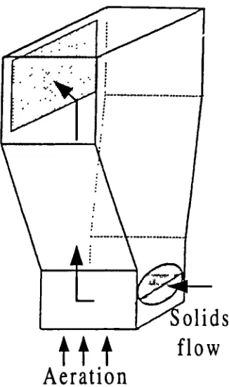
A number of different designs are reported in literature for achieving simultaneous solids circulation coupled with gas separation. Kuramoto et al. (1985) developed a system for circulating fluidized solids within a single vessel intended for biomass or solid waste gasification (see Fig. 3.1). The interior of the vessel (cold model) was divided into four sections by the insertion of two flat plates intersecting at right angles. Fluidized particles were circulated between two up-flowing bubbling and two down-flowing bubble free sections. The effect of the rate of several streams of gas injected at different stages in the bed on the circulation rate of solids, pressure distribution, and residence time of foreign particles in the bed was investigated. The circulation rate of solids was controlled by regulating the velocity of the gas supplied at various levels of the bed.
gas
mass or id waste
gas
Fig. 3.1 Schematic diagram of the circulating fluidized bed for the