Feasible Control Schemes for DSTATCOM to
Mitigate PQ Problems in a Distribution System
T.Neeraja
1, N.M.G.Kumar
2PG Student [EPS], Dept. of EEE, Sree Vidyanikethan Engineering College, Tirupati, India1
Associate Professor, Dept. of EEE, Sree Vidyanikethan Engineering College, Tirupati, India2
ABSTRACT: In the present day situation, the objective of any utility is to provide uninterrupted power with good quality. The quality of power is judged by the parameters like voltage magnitude, power factor, supply frequency and nature of the voltage waveform. The extensive usage of power converters also increases the sensitiveness of the loads. The most power quality problems today are voltage sags, voltage swell, harmonic distortion and low power factor. Hence, recent years the custom power devices are developed which are classified into three categories Dynamic voltage restorer [DVR], Distribution static compensator [DSTATCOM], Unified power quality conditioner [UPQC]. The DSTATCOM is a shunt connected device which takes care of power quality problems at the point of common coupling [PCC].The MATLAB/SIMULINK model is developed for a three phase four wire distribution system to analyse the PQ problems for balanced/unbalanced non-linear loads. The theory of instantaneous symmetrical components has been used because of simplicity in formulation and ease of circulation.
KEYWORDS: Current control mode, power quality (PQ), voltage-control mode, voltage-source inverter.
I.INTRODUCTION
In recent years, there has been an increased emphasis and concern for the quality of power delivered to factories, commercial establishments and residences. This is due to the increasing usage of harmonic creating non linear loads such as adjustable speed drives, switched mode power supplies, arc furnaces etc. Power quality loosely defined, as the study of powering and grounding electronic systems so as to maintain the integrity of the power supplied to the system. IEEE Standard 1159 defines power quality as the concept of powering and grounding sensitive equipment in a manner that is suitable for the operation of that equipment and compatible with the premise wiring system and other connected equipment. The power quality problems in the AC distribution systems are mainly due to the proliferation of different types of non-linear loads, unplanned expansion of the distribution system etc. The causes of power quality problems are generally complex and difficult to detect.
Fig.1 PowerQuality Concerns
Power quality has become an immense concern for both energy suppliers and their customers because of the increasing use of sensitive devices. It causes the poor power quality for the competitiveness of the companies or consumers. This
21st century, the need of electrical energy is every increasing with developments of digital accessories for consumers.
applications etc. for the growth of productivity and life quality are now more common place in both the industrial/commercial environment and the domestic sectors also. The focus of research has been characterization of power quality disturbances, analysis of equipment electro-magnetic compatibility, and improvement of the equipment„s tolerance.
A distribution system suffers from current as well as voltage-related power-quality (PQ) problems, which include poor power factor, distorted source current, and voltage disturbances [1], [2]. To solve PQ problems, typically filters are used which are classified as two types. They are active filters and passive filters. Active filters are special equipments that use power electronic converters to compensate for current and/or voltage harmonics originated by non-linear loads, or to avoid that harmonic voltages might be applied to sensitive loads. There are basically two types of active filters: the shunt type and the series type. It is possible to have active filters combined with passive filters as well as active filters of both types acting together. The causes of power quality problems are generally complex and difficult to detect. Technically speaking, the ideal AC line supply by the utility system should be a pure sine wave of fundamental frequency(50/60HZ). Different power quality problems, their characterisation methods and possible causes are discussed above which are responsible for the lack of quality power which affects the customer in many ways. This project demonstrates that the power electronic based power conditioning using custom power devices like DSTATCOM can be effectively utilised to improve the quality of power supplied to the customer. The prime objective of this project is to mitigate power quality problems in distribution system using DSTATCOM .A three phase four wire distribution system is considered to analyse the power quality problems for balanced/unbalanced non-linear loads.
II.SYSTEM MODEL
Consider a typical radial distribution system, as shown in Figure 2. It consists of a stiff source connected at bus 1 and three load buses. It is assumed that consumers are supplied from these buses[2]. A DSTATCOM can be connected in any of these buses, depending on whether it belongs to the utility or a particular customer. For example, if the voltage at bus 3 is distorted, it affects customers both at buses 3 and 4. The utility may then install a DSTATCOM at this bus to clean up its voltage. On the other hand, suppose that the consumer at bus 4 has loads that draw unbalanced and distorted current from the supply. In order to avoid a penalty, one option for the consumer is to install a DSTATCOM on its premises, so that the current drawn from bus 4 is a balanced sinusoid.
Fig.2 Typical radial distribution systems
(a)
(b)
Fig.3 (a) Compensator structure used where three separate VSIs are supplied from common DC storage capacitor (b) Schematic diagram of DSTATCOM
In the circuit shown in Figure 3(a), each switch represents a power semiconductor device and an anti-parallel diode combination shown in Figure 3(b). Each VSI is connected to the network though a transformer. Six output terminals of the transformer are connected in star. The purpose of including the transformers is to provide isolation between the inverters. This prevents the DC storage capacitor from being short circulated through switches in different inverters[2].
The inductance Lf in Figure 3 represents the leakage inductance of each transformer and additional external inductance,
if any. The switching losses of an inverter and the copper loss of the connecting transformer are represented by a resistance Rf.
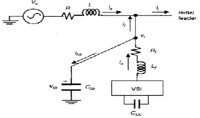
The iron losses of the transformer are neglected. For a star connected load, the neutral point of the three transformers is connected to the load neutral. There are alternative power electronic options that achieve a similar performance. The equivalent circuit of the system under study is shown in Figure 4, with point of common coupling (PCC) is the bus to
which the DSTATCOM is connected. The voltage source (Vs) is the thevenin‟s equivalent voltage looking to the left
of this bus. The thevenin‟s equivalent impedance is represented by the resistance R and inductance L. The source current is denoted by is, and the load current by il. We further define the voltage at the point of common coupling as the
terminal voltage Vt. The DSTATCOM contains a VSI, a DC capacitor (Cdc), a resistance Rf and an inductance (Lf). In
Fig.4 Equivalent circuit of shunt-compensated distribution system
III.CONTROL ALGORITHM FOR DSTATCOM
Figure 3b shows the block diagram of control algorithm of a DSTATCOM based on the correlation and cross correlation purpose for extraction of reference source currents. Fundamental active and reactive power components of load currents for each phase are derived using correlation and cross correlation coefficients and the amplitude of fundamental active and reactive component of load currents are estimated using quadrature and in phase voltage unit templates, zero crossing detector (ZCD) and sample and hold circuit (SHC). The in phase and quadrature unit templates are estimated from phase value of PCC voltages. The zero crossing rising edge of quadrature and in phase voltage templates are the sensed position for extracting the per phase amplitude of fundamental active and reactive power components of load currents with sample and hold circuit. Similarly, amplitude of other phases active and reactive power components of the load currents are also extracted. For balancing the source currents, an average value is derived by the magnitude of active power current components of three phase load currents.
The output of DC bus voltage proportional integral (PI) regulator of VSC of DSTATCOM is added in the average amplitude of active power current component of the three phase load currents and this value is multiplied with three phase in phase unit templates to compute the reference source active power components of currents. Similarly, reference source reactive power components of currents are estimated from the subtraction of an average value of fundamental reactive power components of load currents from the amplitude to output of voltage PI regulator and this value which is multiplied with three phase quadrature components of unit templates. Total reference source currents are estimated by addition of reference active and reactive power components of source currents. Basic equation for estimation of different control signals of control algorithm are given below.
A) System modelling and Generation of a voltage control law
Circuit diagram of a DSTATCOM-compensated distribution system is shown in Figure 5. It uses a three-phase, four-wire, two-level, neutral-point-clamped VSI.
Fig.6 Single phase equivalent circuit
Variable is „u‟ a switching function, and can be either +1 or -1 depending upon switching state. Filter inductance and resistance are Lf and Rf , respectively. Shunt capacitor Cfc eliminates high-switching frequency components.[1] First, discrete modelling of the system is presented to obtain a discrete voltage control law, and it is shown at the PCC voltage can be regulated to the desired value with properly chosen parameters of the VSI. Then, a procedure to design VSI parameters is presented. A proportional integral (PI) controller is used to regulate the dc capacitor voltage at a reference value. Based on instantaneous symmetrical component theory and complex Fourier transform, a reference voltage magnitude generation scheme is proposed that provides the advantages of CCM at nominal load[1].Figure shows the Single-phase equivalent circuit of DSTATCOM. This structure allows independent control to each leg of the VSI. The single-phase equivalent representation of Figure 6, in this section the control design for the DSTATCOM and equivalent circuit of the compensated system is shown in Figure 6, Let us define the following state vector for the circuit shown are given below:
Where
A = B =
B) DSTATCOM in current control mode
In this mode, it is assumed that the installation and maintenance of the DSTATCOM is the duty of an individual customer, so that the load does not disturb other customers, with its unbalance or harmonic distortion. This may be a very stringent condition on the customer, especially when the supply-side voltage is unbalanced or distorted. Nevertheless, we present some design approaches, based on which the customer can draw sinusoidal current from the feeder. We consider three different cases:
(i) When both source and load are unbalanced.
(ii) When both source and loads are unbalanced, and the load is distorted. (iii) When both source and load are unbalanced as well as distorted.
(i): Load and Source Unbalanced: The reference for the terminal voltage is obtained through the Fourier extraction of
the fundamental voltage, i.e.
v
tref=v
tfund. Once this reference is obtained, it is easy to obtain a reference for the current through the filter capacitor. To extract a reference for the injected shunt current, we note that the source currentmust be a fundamental positive sequence. Since
i =i +i
i s f, the compensator must supply the negative and zerosequence required by the load current. We can then write
f0ref 10
i
=i
,i
f2ref=i
12,i
f1ref=0
f s s f f f f L R L L R L C 0 1 0 1 0 1 0 s f dc f L L V C 1 0 0 0 0 0 1 0
tfc fi s
x= v i i
z= v i v
ft s
tload current, it supplies no real power.
(ii): Load and Source Unbalanced and Load Contains Harmonics: The reference for the terminal voltage and current through the filter capacitor is obtained in the same way as Case (i). However, to extract the reference for the injected current, we must remember that the compensator should not only supply the sequence currents, but also should supply the harmonic content of the load. To facilitate this, let us assume that we have obtained ifref from the inverse transformation of i0ref, i1ref, i2ref. We then use the following relation to modify the ifref
fref fref 1 2-und
i
= i
+ i + i
(iii): Load and Source Unbalanced and Distorted: This is the case in which we assume that both the source voltages and load currents are distorted by harmonics. This case has to be treated differently to the previous two cases as the generation of references is of a completely different nature[4]. If we want the source current to be balanced and harmonic-free, then the terminal voltage must contain exactly the same amount of harmonics as the source. However,
the reference for terminal voltage must then be
V
tref=V
tfund+V
sham, wherev
sham is the harmonic content of thesource. Typically, the source does not contain any even harmonics and for phase a is sham m
n=3,5,7...
v
=
v sin nωt
,since
V =i
t filt/c
filt, the reference for the current through the filter-capacitor is then easily obtained. C) DSTATCOM in voltage control mode:We refer to
0
k
1
0
k
c
p
fav, through which the angle of the reference terminal voltage of the DSTATCOM is computed, in order to force the real power drawn by the DSTATCOM to zero. Since the aim is to draw real power from the source, we now modify this equation. To maintain the capacitor voltage as constant, a negativefeedback of this voltage is added in the angle computation as
0
k
1
0
k
c
p
fav
c
v(
v
DCref
v
DCavl)
where C, is constant:v
re fDC is the reference value of the DC capacitor voltage; andv
av lDC is the average value of the DC capacitor voltage. To influence the control rapidly, we have chosen this average to be the running average.IV. RESULT AND DISCUSSION
In this discussions mainly we are considering the voltage sag. Initially there is a fixed inductive load is connected to the line. After 0.2s the circuit breaker is closed and there is no change in terminal voltages and source currents.
Initially inductive load and the circuit breaker with load is connected to the line. After 0.2s the circuit breaker is closed and there is a variation of voltage from 230v to 200v in terminal voltages and 8A to 6A source currents.
Fig.8 Terminal voltages and source currents at balance load with circuit breaker of voltage sag
The non-linear load is connected to the line. After 0.2s the circuit breaker is closed and there is a variation of voltage from 200v to 180v in terminal voltages and 20A to 120A source currents.
Fig.9 Terminal voltages and source currents at unbalance load of voltage sag
I had taken a case study of DSTATCOM connected to 11Kv distribution system. From that I had considered the power quality problem i.e., voltage sag under inductive load and capacitive load.
Fig.11 Terminal voltages and source currents with inductive load with DSTATCOM
Now the capacitive load is connected to the line with Dstatcom. The circuit breaker is closed at 0.2s and the voltage sag is reduced and the source currents varies.
Fig.12 Terminal voltages and source currents with capacitive load with DSTATCOM
Now the inductive load and capacitive load is connected to the line. After placing the D statcom the voltage sag gets reduced. The terminal voltages do not changes during both linear and non linear loads. The source currents remains zero after 0.2s there is increase in currents until 0.26s.
V.CONCLUSION
Custom power devices can be used, at reasonable cost, to provide high quality and improved power service. These custom power devices provide solutions to power quality at the medium voltage distribution network level. This project presents the detailed modelling of one of the custom power device, DSTATCOM is presented. DSTATCOM can provide effective solution to the power quality problems. By placing the DSTATCOM at the point of common coupling , the voltage disturbances are reduced by using different control strategies and the reactive power is also compensated. The power quality problems and harmonics are mitigated by placing the DSTATCOM in the distribution system.. In this project the detailed modelling of DSTATCOM is presented. DSTATCOM can provide efficient solution to the power quality problems. Hence, the control strategy is tested with three phase four wire distribution system.
REFERENCES
[1] Chandan Kumar, Mahesh K.Mishra, “A Voltage-Controlled DSTATCOM for Power- Quality Improvement,” IEEE Transactions on Power Delivery, vol.29, no.3, pp1499-1507, June2014.
[2] M. K. Mishra, A. Ghosh, and A. Joshi, “Operation of a DSTATCOM in voltage control mode,” IEEE Transactions on Power Delivery, vol. 18, no. 1, pp. 258–264, Jan. 2003
[3] Satyaveer Gupt, Ankit Dixit, Nikhil Mishra, S.P. Singh, “Custom Power Devices For Power Quality Improvement,” International Journal of Research in Engineering & Applied Science, Vol.2, Issue 2, February 2012.
[4] G. Ledwich and A. Ghosh, “A flexible DSTATCOM operating in voltage or current control mode”, IEE Proceedings in Generation Transmission and Distribution, Vol. 149, No. 2, March 2002
[5] T. Srikanth, “Compensating linear and non linear loads using distribution static compensator (DSTATCOM)”, Journal of Electrical and Electronics Engineering Research, Vol. 5(2), pp. 28-43, August 2013
[6] Ankush Sharma, “Power Quality Improvement for DSTATCOM in Distribution System”, International Journal of Innovative Research & Development, Vol 3, Issue 9, September, 2014.
[7] Mr.Ch. Venkata Krishna Reddy, Dr. K.Krishna Veni, Dr.G.Tulasiram Das And Dr. Sampath.Pulla, “performance analysis of DSTATCOM compensator using control techniques for load compensation”, International Journal of Electrical and Electronics Engineering Research (IJEEER), Vol.1, Issue 2 Dec 2011 149-171.
[8]M. K. Mishra, A. Ghosh, A. Joshi, and H. M. Suryawanshi, “A novel method of load compensation under unbalanced and distorted volt- ages,”
IEEE Transactions on PowerDelivery, vol.22,no.1, pp.288–295, Jan.2007.
[9] P. Bapaiah, “Power Quality Improvement by using DSTATCOM”, International Journal of Emerging Trends in Electrical and Electronics (IJETEE) Vol. 2, Issue 4, April-2013.
[10] U. Koteswara Rao, Mahesh K. Mishra, Member, and Arindam Ghosh, Fellow, “Control Strategies for Load Compensation Using Instantaneous Symmetrical Component Theory Under Different Supply Voltages”, IEEE Transactions On Power Delivery, Vol. 23, No. 4, October 2008.
[11] Ankush Sharma, “Review Paper on Applications of DSTATCOM in Distribution System”, International Journal of Science and Modern Engineering (IJISME), ISSN: 2319-6386, Volume-2, Issue-11, October 2014.
[12] R.Geetha, M.Aishwariya Devi, “Various Control Techniques For Power Quality Improvement Using DSTATCOM,” International Journal of Power Control Signal and Computation (IJPCSC), volume 4, No. 2, April- June -2012.
[13] K.R.Padiyar, “FACTS controllers in power transmission and distribution”, New Age International Publishers, First edition 2007. [14] www.ieeexplore.org.com