Article
Numerical Simulation of a Vortex Combustor Based
on Aluminum and Steam
Xianhe Chen 1, Zhixun Xia 1,*, Liya Huang 2 and Likun Ma 1
1 Science and Technology on Scramjet Laboratory, National University of Defense Technology,
Changsha 410073, China; [email protected] (L.M.)
2 Department of Aerospace Science and Engineering, National University of Defense Technology,
Changsha 410073, China; [email protected]
* Correspondence: [email protected]
Abstract: In this paper we report a new development on the numerical model for aluminum-steam combustion. This model is based on diffusion flame of continuum regime and the thermal equilibrium between the particle and the flow field, which can be used to calculate the aluminum particle combustion model for two phase calculation conditions. The model prediction is in good agreement with the experimental data. A new type of vortex combustor was proposed for the combustion of aluminum and steam, and the mathematical model of the two phase reacting flow with in this combustor was established. The turbulence effects are modeled using the Reynolds Stress Model (RSM) with Linear Pressure-Strain approach, and the Eddy-Dissipation model is used to simulate the gas phase combustion. Aluminum particles are injected into the vortex combustor and form a swirling flow around the chamber and their trajectories are traced using the Discrete Phase Model (DPM). The simulation results show that the vortex combustor can achieve high efficient combustion of aluminum and steam. The influencing factors, such as the eccentric distance of the inlet of aluminum particles, particle size and steam inlet diameter, etc., are studied. The work described in this paper represents an attempt to the design of a vortex combustor in order to increase aluminum combustion efficiency.
Keywords: aluminum particle; steam; vortex combustor; diffusion flame; numerical simulation
1. Introduction
Aluminum is an important energetic component of many solid propellants, explosives, and
pyrotechnic formulations. In addition, aluminum is used as a new energy materials since
aluminum-water reaction could produce hydrogen and to form aluminum fuel cell[1]. In recent
years, many aspects of the aluminum and water reactions are researched in the aluminum-water
ramjet and aluminum-water power systems such as HAC[2], HAC-SOFC[3,4]. At present, the
aluminum-water mixture is made into a solid grain[5-8] by using the characteristics of the slow
reaction of the aluminum-water at low temperature. For undersea vehicles, the use of external water
and its own carrying aluminum reaction can greatly improve the performance of the power system.
Besides, the water ramjet engine using similar principle of ramjet was researched. Considering the
fact that the aluminum and liquid water reaction is difficult, the water ramjet engine uses fuel rich
propellant, in general, in order to realize water aluminum combustion. However, by doing so, the
aluminum content is reduced, and therefore the engine performance is lowered. Undoubtedly, if
pure Al powder is used, the engine performance will be the highest. Therefore, a concept of vortex
combustor was proposed by T. F. Miller[9,10] and the experimental study was carried out. It is
achieved. However, there is no relevant research report on the performance optimization and
calculation of the vortex combustor.
According to the existing research, the combustion law of aluminum particles is basically based
on the combustion experiments[11-17] of single particle and particle group, and the various laws of
particle size and burning time were obtained, such as D1.8 and D1.5. At the same time, there are many
researchers from the perspective of the mathematical model theory[14,18-22], that when the particle
size of aluminum particles is large, the combustion is controlled by continuum regime, whereas, for
the nano aluminum particles, the combustion is controlled by free-molecular regime, and when the
particle size is between this two, the combustion is controlled by transition regime. In the calculation
of current flow field of aluminum particle, the burning time change law (Dn law) of aluminum
particles obtained by experiment is basically adopted, however, this law only reflects the change of
particle burning time with particle size, but cannot accurately describe the particle size change
process with time, so there are some limitations in the calculation results.
According to the previous research, this paper draws on the research ideas of the gas flame
from Salil Mohan[19], the existence of flame on the surface of aluminum particles is assumed. Under
the condition of the thermal equilibrium between the particle and the flow field, a simplified
combustion model of aluminum particles is obtained, which can be used for the calculation of the
two-phase flow of aluminum particles and can describe the particle combustion process completely.
The results for this model are verified. At the same time, the vortex combustor was designed
according to the concept of vortex combustor proposed by T. F. Miller, and the simulation
calculation was carried out. Besides, the aluminum water chamber performance under the condition
of the different aluminum particle size, steam temperature, aluminum water mass ratio and vortex
combustor configuration are obtained.
2. Physical and numerical model
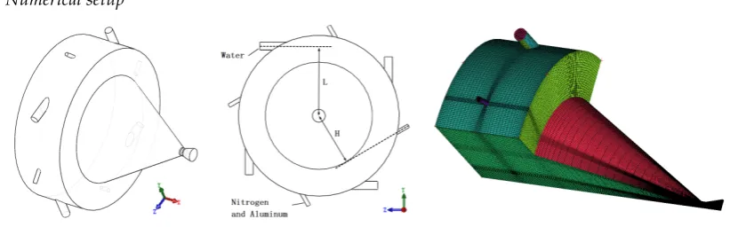
2.1. Numerical setup
Figure 1. Vortex combustor configuration diagram
A vortex combustor configuration which use four circumferential steam inlet and four
circumferential aluminum particles inlet were proposed according to the concept of vortex
combustor from T.F. Miller[9], see Figure 1. In order to ensure that the aluminum particles are fully
heated and ignited, the recessed cavity configuration is provided in the swirl chamber. In order to
facilitate the mesh generation, the model configuration doesn’t use completely tangent inlet
conditions, but take eccentric sprayed into the design. According to the calculation results, particle
as gravity, so gravity are not considered. Therefore, to reduce the computational cost, only a quarter
of the combustor was simulated with periodic boundary conditions in this paper.
2.2. Models and boundary conditions
In consideration of the existence of a strong swirl flow field in the vortex combustor, the
turbulence effects were modeled using the Reynolds-Stress Model (RSM) with Linear
Pressure-Strain approach. Meanwhile, Eddy-Dissipation model is used to simulate the gas phase
combustion and the simulations were carried out under steady state conditions.
If there is no special declaration, in all cases, the chamber diameter is equal to 150mm, length is
equal to 50mm, L=65mm, H=30mm, the steam mass flow rate is 4x5g/s [10], steam temperature is
equal to 750K, the aluminum mass flow rate is 4x4g/s, Nitrogen mass flow rate is 4x2g/s, d=10um,
D=6mm, the diameter of the Nitrogen inlet is equal to 3mm.
The wall is set to adiabatic boundary condition
,
and it is assumed that the particle will betrapped if it is in the liquid state when collide with the wall.
2.3. Models and boundary conditions
Because that the aluminum particle burning time correlations from experimental (such as the
law of D1.8) only reflects the change of particle burning time with particle size, but cannot accurately
describe the particle size change process with time. So the burning time correlation is not adopted in
here. Taking into account the use of micron aluminum particle in this paper, we adopt the diffusion
control of the continuum regime.
For diffusion-controlled conditions, the particle mass consumption rate are given by[23],
(
,)
2 ln 1
4 ox O D m iY r r ρ π = + ∞ (1)
Taking into account that the alumina cap will have a certain effect on the combustion of
particles, the relationship between the particle mass change and the effective surface area and the
particle radius can be obtained in the flow field:
(
,)
ln 1 Al ox O S D m iY r ρ ∞ = + (2)
The diffusivity of gases is given by [23]
1/ 2 3
ox 3 2
2 3
B A
k TN T
D
MW p
π σ
=
(3)
The oxide caps of the aluminum droplets grow as the droplets collide and agglomerate with the
oxide particles. This collision process is driven by the relative velocity between the particle and the
surrounding alumina. The model of alumina deposition is given by[24]:
2 16
dep
p g s c
dm
r C
dt
π η
= u −u
(4)
Most of the aluminum particle ignition theory [16,17,25,26] is that the particle ignites success
when particle temperature reach to the rupture temperature of the oxide layer and the ignition
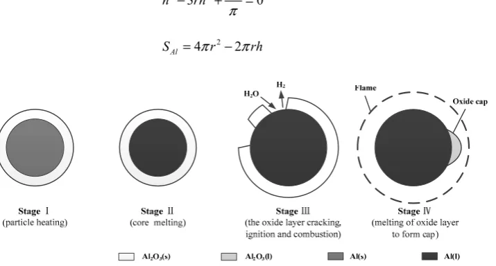
The combustion of aluminum particles can be divided into four stages: the particle heating, the
particle melting, the particle ignited to the alumina cap form, and the particles burning (see Figure 3). Due to the fact thatBi hD= p/kp<0.01, it is assumed that the particle temperature is uniform but time
varying. The heat exchange between the particle and the environment is through convection heat
transfer, radiation heat transfer, chemical reaction heat, latent heat of vaporization and condensation
heat and so on.
A model for SAl was proposed in Melcher [21], as illustrated in Figure 2.
Figure 2. Model of oxide deposition on the aluminum particle surface
3 3 2 3V 0
h rh
π
− + =
(5)
2
4 2
Al
S = πr − πrh
(6)
Figure 3. Configuration showing an Al particle ignition and combustion procedure
Stage Ⅰ: particle heating. This stage finished before the melting of aluminum particles, aluminum surface initial covering a layer of oxide layer. According to the conclusion of the literature, the
thickness of the oxide layer is generally in between 2 to 4 nm[28], and the 4 nm thickness is used in
this paper. Assuming that the heating process is quick, no chemical reactions take place, the heat exchange of particle includes the convection heat Qconv, radiation heat Qrad and condensation heat
cond Q .
p
p p conv rad cond
dT
m c Q Q Q
dt = + + (7)
Where
(
)
g
g P
conv p g p p
g
C
Q A T T Nu
Pr
ν ρ
= −
(8)
(
4 4)
rad p B p g p
Q =ε k A T −T
( ) ( )
(
)
cond dep p g
Q =m h T −h T
(10)
Stage Ⅱ: from aluminum particles melting to the particle ignition. The phase of aluminum is liquid,
alumina is solid and particle size is unchanged. Assuming that there is no chemical reactions take place too. Qphase Al, is the aluminum heat of phase transformation.
,
p
p p conv rad phase Al cond
dT
m c Q Q Q Q
dt = + + + (11)
Stage Ⅲ: from ignition of aluminum particles to alumina melts. At this stage, the expansion of the
liquid aluminum enlarges the particle size, resulting in the oxide layer rupture, and the aluminum
particles start to ignite and burn; The thermal characteristics of this stage show that the exposed
aluminum oxidation reaction with water, resulting in the heat used for heating the aluminum core
and alumina. The oxide layer grows until the fully melting of aluminum oxide, which indicates the end of this stage. Qphase Al, 2 3O
is the alumina melting heat. The exposed aluminum particle surface area
Al
S is equal to the surface area of the aluminum particle surface area S minus the internal surface
area of initial oxidation layer Sinit. When the temperature reaches the melting point of aluminum
oxide, SAl is equal to the greater one between this value and the area from equation(6). In this stage,
when SAl≤0, the aluminum particle extinguish.
2 3
,
p
p p conv rad comb phase Al O cond
dT
m c Q Q Q Q Q
dt = + + + + (12)
init
Al
S = −S S (13)
Stage Ⅳ: alumina melt completely and formed alumina cap on the surface of the particle, and
aluminum particles produce gas phase combustion flame. This stage can be divided into two states.
1. Gas phase flame exist on the particle surface. When the particle temperature is lower than the
boiling point of aluminum, if the reaction heat release is greater than the heat released by the
particles to the surrounding environment, the gas phase flame exists on the surface of the
particle. Suppose that the reaction mass fraction of aluminum that reacts at the particle surface
isα, When the particle temperature reaches the boiling point of aluminum, assuming that
combustion is pure gas phase combustion andα=0. Due to the presence of a flame on the
surface of the particles, the heat exchange between the particles and the surrounding
environment is considered as a heat exchange between the flame and the environment, and in
the calculation, this part of the energy is not taken into account in the calculation of the temperature change of the particle itself. SAl is calculated by equation(6).
p
p p comb cond
dT
m c Q Q
dt =α + (14)
2. There is no gas phase flame on the particle surface. If the reaction heat release is lower than the
particles to the surrounding environment, then α =1, which means that only the particle
surface oxidation reaction happens, and not flame exists on particle surface. The heat exchange
between the particle and the environment has to be considered in this situation.
p
p p conv rad comb cond
dT
m c Q Q Q Q
Besides, when the oxidant concentration is 0, and the external environment temperature is
greater than the particle temperature then the particles combustion are controlled by evaporation
mechanism, at this time the particle temperature is maintained at the boiling point.
2.4 Particle motion
The aluminum particles are tracked in a Lagrangian way. The trajectory of aluminum particles
in the flow field is traced by a stochastic trajectory model. Under the plane rectangular Descartes
coordinate system, the influence of the random velocity of the gas phase on motion of particles is not
considered, the governing equations for the particle are
p p
d dt =u
x
(16)
p p
d
dt = +
u F F (17)
(
)
3 4 Dp g p g p
p C d ρ ρ = − −
F u u u u
18)
The drag coefficient of particles CD[29] is
(
2/3)
24 1 / 6 / 1000
0.424 1000
p p p
D
p
Re Re for Re
C for Re + ≤ = >
(19)
g p p g d Re ν −
= u u
(20)
3. Results and discussion
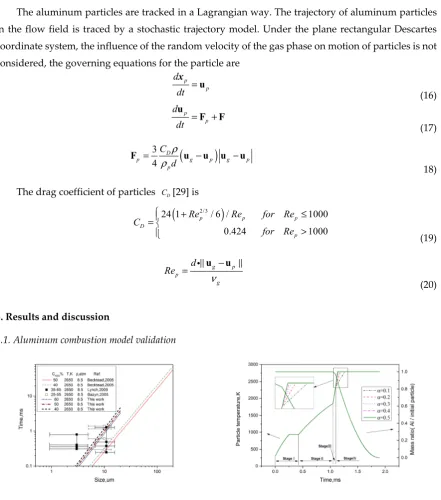
3.1. Aluminum combustion model validation
Figure 4. Combustion time as a function of particle
size for Al particle
Figure 5. Particle temperature and mass ratio as a
function of combustion time for Al particle
The calculated results using the aforementioned model as well as some of the earlier results [30]
and correlations are shown in Figure 4. And the large error bars account for the width of the size
distributions for the sieved powders. According to Figure 4, the burning time was slightly larger
than the results of Becktead, between the results of Lynch and bazyn, so that this model can better
response out the combustion variation law of aluminum particles. In addition, the model has good
alumina cap, meanwhile, the real aluminum particle surface area was replaced by effective area
when calculate the particle mass change, there has a certain deviation between calculated values and
the experimental values. For particles smaller than 5um, the diffusion control of continuum regime
may not be applicable, thus this model is not useable for it.
Figure 5 shows the change of the temperature and the particle mass ratio of 10 micron
aluminum particles in ambient temperature 2650K, pressure 8.5atm, water mole fraction of 0.5.
According to the calculation results, the change of temperature is consistent with the model. In
StageⅠ, particle was heated up to the melting point, then aluminum melts completely; In StageⅡ,
particle was continuously heatedup to the aluminum ignition temperature. In StageⅢ, after the
success of ignition, under the condition of reaction heat and ambient heat exchange, particle
temperature quickly climbs to alumina melting point. Due to the release of a large amount of heat,
alumina melts rapidly. In StageⅣ, with surface reaction and gas phase combustion, particle
temperature arrived at the boiling point, and gas-phase flame was formed ultimately. The value of
α affects the process of the particle temperature change from alumina melts to the final gas phase
flame. The smaller of the α , the smaller of the surface reaction heat, and the slower of the
temperature rise rate. But the temperature rise rate is almost constant after α >0.3. Similarly, after
αmore than 0.3, the combustion time remained essentially unchanged. It can be known that when
α is greater than 0.3, it can get a relatively stable particle combustion variation law, so the
following calculation and the previous value verify takes α=0.3.
3.2 Flow field analysis
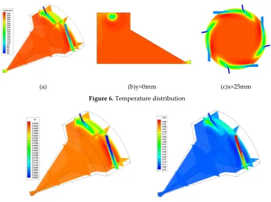
Figure 6 shows the temperature field distribution. The final temperature is about 3170K, this
value are in agreement with the thermodynamic calculation results (3175K). Figure 6(a), Figure 7
and Figure 8 show that the low temperature area are mainly distributed in the configuration of
peripheral and near of the steam and aluminum particle inlet. However, the high temperature area is
mainly located in inside the cavity structure, which means the region of the cavity is the main
combustion zone (Figure 7). According to the configuration, the steam is approximately tangential to
enter the combustion chamber to form a swirl flow firstly, and then moving from outside to inside,
and finally flows out of the combustion chamber. So steam mainly exists in the cavity region (Figure
8). When the aluminum particles enter into the combustion chamber, also with the airflow for swirl
flow, so that the residence time of aluminum particles in the combustion chamber is longer, and this
facilitates the combustion of aluminum particles. Figure 6(b) shows the high temperature region
tends to burn in the front-end, indicating that most of the aluminum particles tend to rotate in the
front-end of the combustion chamber. Figure 6(c) shows the x=25mm section complete temperature
distribution. According to the ignition temperature of aluminum particles, the ignition temperature
of 10 micron aluminum particles is about 1846K, while the figure shows that the temperature in most
parts of the combustion chamber is greater than 2050K, which is convenient for the ignition of
(a) (b)y=0mm (c)x=25mm
Figure 6. Temperature distribution
Figure 7. Hydrogen mass fraction distribution Figure 8. Water mass fraction distribution
Figure 9 and Figure 10 show the distribution of Al particle ignition delay time and burning
time. In this case, aluminum particles average ignition delay time is equal to 2.678ms and average
burning time is equal to 1.726ms, longer than the burning of single aluminum particle combustion,
but most of the particles combustion time is within 2ms, and ignition delay time is less than 3.5ms.
The main reason is that in the combustion chamber, with the burning of aluminum particles, the H2O
is gradually consumed and the H2O mass fraction is distributed inhomogeneous, so the burning
time of aluminum particles are distributed differently. Particle residence time in the chamber is
equal to the ignition delay time plus the burning time, which shows that the residence time of most
of the aluminum particles is less than 5.5ms.
The trap ratio ηtrap is defined as the percentage of aluminum particle trapped by the
combustion chamber wall before combust completely.
/
trap Ntrap Ntotal
η = (21)
The combustion efficiency can be calculated as such:
2 2 2
2 2
,in ,out
2 2 ( )
3 3
Al H O Al H O H O
Al
Al H O Al H O Al
M m M m m
m
m M m M m
η=Δ = Δ = −
(22)
According to the statistics of this case, the trapped rate of aluminum particles is about 5.72%,
and the total combustion efficiency is about 97.87%. It can be found that, in a given initial conditions,
aluminum particles have a relatively high combustion efficiency in the configuration of this vortex
Figure 9. Ignition delay time distribution of Al particles Figure 10. Burning time distribution of Al particles
3.3 Effects of eccentric distance of the inlet of aluminum
According to the combustion chamber configurations, when eccentric distance H different,
aluminum particles into combustion chamber location is not the same, may be made of aluminum
particle combustion effect is not the same, so this section of H were taken 70mm, 50mm, 30 mm and
0mm effect on combustion process of aluminum particles research. In order to facilitate the data
analysis, the parameters of the x=25mm cross section and the circumferential 45°line were taken as
the representation.
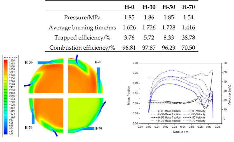
Table 1. Calculation result parameter distribution
H-0 H-30 H-50 H-70
Pressure/MPa 1.85 1.86 1.85 1.54
Average burning time/ms 1.626 1.726 1.728 1.416
Trapped efficiency/% 3.76 5.72 8.33 38.78
Combustion efficiency/% 96.81 97.87 96.29 70.50
Figure 11. Temperature distribution Figure 12. Velocity and H2O mass fraction distribution
Table 1 shows that with the increase of H, the combustion efficiency, chamber pressure and
particle burning time increases first and then decreases, however, particle trapped efficiency
increases gradually. On one hand, in the case of the same primary particle size, the gas velocity
increases(see Figure 12) with the increase of H, thus the greater the centrifugal force which may
cause the particles tend to move toward the periphery of the combustion chamber, which causes he
particles to be trapped in the wall, and the combustion efficiency is reduced. On the other hand, with
the increase of H, the particle are closer to the wall when they enter combustion chamber, which
efficiency decreased. In addition, the particle average burning time are increased first and then
decreased with the increase of H. This is because the combustion efficiency are increased first and
then decreased with the increase of H, and the concentration of steam are decreased first and then
increased(see Figure 12), which leads to the particle burning rate decreased first and then increased,
therefore, the particle average burning time are increased first and then decreased.
Figure 11 shows that, temperature distribution was consistent basically in H-0, H-30 and H-50,
the difference among them is: the highest temperature was decreased with the H increased.
Meanwhile, the temperature was decreased rapidly in H-70. This is because the combustion
efficiency are consistent basically in H-0, H-30 and H-50, and the combustion efficiency only 70.5%
in H-70. From the velocity curve in Figure 12, it can be known that the velocity increases with the
increase of H in most regions.
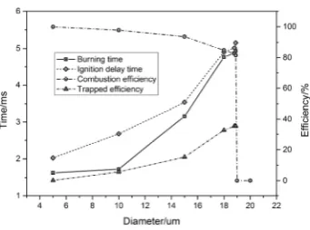
3.4 Effects of particle sizes
The diameters of the particles d were 5um, 10um, 15um, 18um, 19um and 20um respectively. As
is shown in Figure 13, with the particle size increased, combustion efficiency decreases gradually,
and the reduction rate increases gradually; finally in the particle size 18.5um to 19um appeared a
step, which means when the particle sizes larger than 19um, aluminum particles will not be able to
maintain combustion. That is to say when the particle size is large enough, the combustion efficiency
reaches the critical value, and when the combustion efficiency is lower than the value, the aluminum
particles will not be able to sustain combustion under this configuration. According to the burning
time curve, the burning time increases with the increase of particle size; The variation of burning
time with particle size was obtained by curve fitting: t=1.46948 2.2709+ E−4d3.28751. According to the
configuration of the combustion chamber, the aluminum particles enter into the combustion
chamber at an angle to rotate with the gas flow, similar to the principle of the cyclone separator, the
particles with gas from outside to inside rotates and finally exhausted from the combustion
chamber. When the particle size is smaller, the aluminum particles are easily ignited successfully
because of the high temperature of the combustion chamber, and the majority of the particles are
burned before the collision between the particle and the wall, and the combustion efficiency is high;
When the particle size is large, the particle ignition delay time increased. Under the influence of
centrifugal force and resistance factors, successful ignition particles are trapped before burning
completely or even most of them were not completed, so that the combustion efficiency decreases,
leading to combustion chamber temperature is further reduced, and ignition delay time continues to
increase, the combustion efficiency continues to decline, ultimately makes the aluminum particles
Figure 13. Distribution of combustion efficiency, ignition delay time , burning time and trapped efficiency under the different particle sizes
3.5 Effects of steam inlet diameter
This section takes different steam inlet diameter D=4mm, 5mm, 6mm,and 7mm respectively.
Table 2. Calculation result parameter distribution
D-4 D-5 D-6 D-7
Pressure/MPa 1.57 1.76 1.86 1.88
Average burning time/ms 1.369 1.679 1.726 1.895
Trapped efficiency/% 38.23 10.54 5.72 3.196
Combustion efficiency/% 71.62 95.55 97.87 98.84
According to the results of Table 2, with the increase of D, the combustion chamber pressure,
burning time and combustion efficiency are increased, however, the trapped efficiency is decreased.
It can be known that the larger inlet steam diameter can improve the combustion efficiency of
aluminum particles. According to Figure 14, with the increase of D, the gas velocity in the chamber is
decreased; Under the condition of the same particle size of aluminum particles, the lower gas
velocity makes the aluminum particles speed is lower, Therefore, in the same displacement
conditions, the larger of D corresponding to a long running time for aluminum particles, then before
the aluminum particles collide or flow out of the combustion chamber, there is sufficient time to
achieve particle combustion. In addition, with the increase of combustion efficiency, the mass
fraction of H2O in the flow field is decreased, and the combustion time of aluminum particles is
shortened according to the law of the combustion of aluminum particles.
4. Conclusions
An aluminum particle combustion model is established based on the diffusion flame of
continuum regime and the thermal equilibrium between the particle and the flow field. This model
can be used in the simulation of the aluminum particle combustion model in two-phase flow. At the
same time, the influence of intial oxidation layer, alumina cap and the alumina deposition on
combustion are considered. The model results are in good agreement with the experimental results.
A vortex combustor is designed and simulated, and the flow field structure parameters under
the configuration condition are obtained. The results show that the configuration can achieve a
relatively high efficiency of combustion.
The influences of different eccentric distance of the inlet of aluminum particles, aluminum
particle size and the steam inlet diameter on the performance of the combustion chamber are
analyzed. With the increase of the eccentric distance of the inlet of aluminum, the combustion
efficiency, chamber pressure and particle burning time are increased first and then decrease,
however, particle trapped efficiency increased gradually. With particle size increased, combustion
efficiency decreases gradually, and the reduction rate increases gradually. When the particle size is
large enough, the combustion efficiency reaches a critical value, and when the combustion efficiency
is lower than the value, the aluminum particles will not be able to sustain combustion. With the
increase of the steam inlet diameter, the pressure of the combustion chamber is increased, the flow
velocity of the combustion chamber is reduced, the average combustion time of the aluminum
particles is increased and the combustion efficiency is increased.
Nomenclature
p
A =particle surface area(m2)
s
C =the local concentration of oxide
p
c =particle specific heat(J/(kg·K))
g
P
c =gas specific heat(J/(kg·K))
D
C =drag coefficient
d = particle diameter(um)
D = the diameter of the steam inlet(mm) ox
D = the diffusivity of oxidizer(m2/s)
trap
η =trap ratio
η= combustion efficiency
c
η =collision efficiency, 0.25
p
ε =radiation coefficient
p
F =drag force per unit particle mass(N/kg)
F=additional force such as Stefan force(N/kg)
H = the eccentric distance of the aluminum particle inlet(mm)
h =the height of oxide deposition(m)
( )
ph T =alumina enthalpy at Tp (W/kg)
( )
ch T =alumina enthalpy at Tg (W/kg)
B
k = Boltzmann constant
L = the eccentric distance of the steam inlet(mm) m=mass consumption rate of particle (kg/s)
dep
m =oxide deposition mass(kg)
Al
m
Δ =aluminum consumption(kg)
Al
m = inlet aluminum mass(kg)
Al
M = Aluminum molecular weight(kg/mole)
2
H O
M
= H2O molecular weight(kg/mole)
2 H O m
Δ =the consumption of H2O(kg)
2 ,in H O
m = inlet H2O mass(kg)
2 ,out H O
m = outlet H2O mass(kg)
MW =molecular weight of oxidizer(kg/mole)
A
N =Avogadro number
trap
N =trapped particle number
total
N = total particle number
p = pressure(Pa) g
Pr =Prandtl number
conv
Q =convection heat(W)
rad
Q =radiation heat(W)
cond
Q =condensation heat(W)
ρ=gas density(kg/m3)
r =particle radius(um) p
Re =particle Reynolds number
Al
S =aluminum surface area exposed in the environment(m2)
σ =molecular diameter(m)
p
T =particle temperature(K)
g
T =gas temperature(K)
p
u =particle velocity(m/s)
g
u =gas velocity(m/s)
V =the volume of the oxide cap(m3) g
ν =kinematic viscosity(Pa·s)
p
x =particle location
,
O
References
1. Mercati S, Milani M, Montorsi L, Paltrinieri F.. Design of the steam generator in an energy conversion system based on the aluminum combustion with water. J. Applied Energy . 2012, 97(0), 686-694.
2. Daniel F. W. , Christopher P.C. , W. Ethan Eagle. Quantifying Unmanned Undersea Vehicle Range Improvement Enabled by Aluminum-Water Power System. J. Journal of propulsion and power. 2013, 29(3), 675-685.
3. Daniel F. W. ,Christopher P. C. . Modeling a hybrid Rankine-cycle/fuel-cell underwater propulsion system based on aluminum water combustion. J. Journal of Power Sources. 2013,221, 272-283.
4. Daniel F. W. ,Christopher P. C. . Estimating the neutrally buoyant energy density of a
Rankine-cycle/fuel-cell underwater propulsion system. J. Journal of Power Sources. 2014, 248, 714-720. 5. Dilip Srinivas Sundaram, Vigor Yang, Ying Huang, Grant A. Risha, Richard A. Yetter. Effects of particle
size and pressure on combustion of nano-aluminum particles and liquid water. Combustion and Flame. 2013, 160, 2251–2259.
6. Terrence L. Connell Jr., Grant A. Risha, Richard A. Yetter, Gregory Young, Dilip S. Sundaram, Vigor Yang. Combustion of alane and aluminum with water for hydrogen and thermal energy generation. Proceedings of the Combustion Institute, doi:10.1016/j.proci.2010.07.088.
7. J.L. Sabourina, G.A.Risha, R.A.Yetter, S.F.Son, B.C. Tappan. Combustion characteristics of nanoaluminum, liquid water, and hydrogen peroxide mixtures. Combustion and Flame. 2008,154, 587–600.
8. David Greatrix. Numerical Evaluation of the Use of Aluminum Particles for Enhancing Solid Rocket Motor combustion Stability. Energies. 2015, 8, 1195-1215; doi:10.3390/en8021195.
9. T.F.Miller, J.L.Walter, D.H.Kiely. A next-generation AUV energy system based on aluminum-seawater combustion. Proceedings of 2002 Workshop on Autonomous Underwater Vehicles. San Antonio, 2002. 10. Timothy F. Miller, John D. Herr. Green Rocket Propulsion by Reaction of Al and Mg Powders and Water.
40th AIAA/ASME/SAE/ASEE Joint Propulsion Conference and Exhibit, American Institute of Aeronautics and Astronautics, 2004, doi: http://dx.doi.org/10.2514/6.2004-4037.
11. Amy Corcoran, Stefano Mercati, Hongqi Nie, Massimo Milani, Luca Montorsi, Edward L. Dreizin. Combustion of fine aluminum and magnesium powders in water. Combustion and Flame. 2013, 160(10): 2242-2250.
12. M. W. Beckstead. Correlating Aluminum Burning Times[J[. Combustion, Explosion, and Shock Waves. 2005, 41 (5) , 533–546.
13. Dilip Srinivas Sundaram, Vigor Yang. Combustion of micron-sized aluminum particle, liquid water, and hydrogen peroxide mixtures. Combustion and Flame.2014, 161, 2469–2478.
14. D. S. Sundaram, V.Yang, V.E.Zarko. Combustion of Nano Aluminum Particles (Review). Combustion, Explosion, and Shock Waves. 2015, 51(2): 173–196.
15. Robert J. Gill, Carlo Badiola, Edward L. Dreizin. Combustion times and emission profiles of micron-sized aluminum particles burning in different environments. Combustion and Flame. 2010, 157, 2015–2023. 16. Jihwan Lim, Heesung Yang, Woongsup Yoon. Burning and Ignition Characteristics of Single Aluminum
and Magnesium Particle. 46th AIAA/ASME/SAE/ASEE Joint Propulsion Conference & Exhibit. DOI: 10.2514/6.2010-6676.
17. Mirko Schoenitz, Salil Mohan, Chi-Mon Chen, and Edward L. Dreizin. Oxidation and Ignition of Aluminum Particles in the Presence of Water Vapor. 44th AIAA/ASME/SAE/ASEE Joint Propulsion Conference & Exhibit. DOI: 10.2514/6.2008-4719.
18. Alexandre Ermoline, Deniz Yildiz, Edward L. Dreizin. Model of heterogeneous combustion of small particles[J]. Combustion and Flame. 160 (2013): 2982–2989.
19. Salil Mohan, Mikhaylo A. Trunov, Edward L. Dreizin. On possibility of vapor-phase combustion for fine aluminum particles. Combustion and Flame. 2009, 156, 2213–2216.
20. Bojko B T, DesJardin P E, Washburn E B. Modeling Transitional Burning Modes of Aluminum Particles. 8th US National Combustion Meeting, Paper # 070HE-0397, 2013.
21. E. B. Washburn, J. N. Trivedi , L. Catoire, M. W. Beckstead. The Simulation of the Combustion of Micrometer-Sized Aluminum Particles with Steam. Combustion Science and Technology, 180:8, 1502-1517, doi: 10.1080/00102200802125594.
23. Richard A. Yetter, Grant A. Risha, Steven F. Son. Metal particle combustion and nanotechnology[J]. Proceedings of the Combustion Institute, 32 (2009): 1819–1838.
24. F.M.Najjar, J.P.Ferry, A.Haselbacher, and S. Balachander. Simulations of Solid-Propellant Rockets: Effects of Aluminum Droplet Size Distribution. Journal of Spacecraft And Rockets. 2006,43,1258-1270.
25. Eric Boyd, Ryan Houim, Kenneth K. Kuo. Ignition and Combustion of Nickel Coated and Uncoated Aluminum Particles in Hot Post-Flame Environment. 45th AIAA/ASME/SAE/ASEE Joint Propulsion Conference & Exhibit, 2009, Denver, Colorado.
26. V. Rosenband. Thermo-mechanical aspects of the heterogeneous ignition of metals. Combustion and Flame. 2004,137, 366–375.
27. Ying Huang, Grant A. Risha, Vigor Yang, Richard A. Yetter. Flame Propagation in Bimodal
Nano/Micro-Sized Aluminum Particles/Air Mixtures. 44th AIAA Aerospace Sciences Meeting and Exhibit, 2006, Reno, Nevada. doi: http://arc.aiaa.org / DOI: 10.2514/6.2006-1155.
28. Norbert Eisenreich, Harald Fietzek, et al. On the Mechanism of Low Temperature Oxidation for Aluminum Particles down to the Nano-Scale. Propellants, Explosives, Pyrotechnics. 2004,29,137-145. 29. Prasanth George, Paul E. DesJardin. Effects of Heterogenous of surface reactions on the ignition of
aluminum particles. 42nd AIAA Aerospace Sciences Meeting and Exhibit. AIAA 2004-790.
30. Amy Corcoran, Stefano Mercati, et al. Combustion of fine aluminum and magnesium powders in water. Combustion and Flame. 2013,160, 2242-2250.