Surveillance Drone
Pranit Barhate, Nakul Bhandare, Akshay Barve
Department of Computer Engineering, MCOERC, Nasik, Maharashtra, India ABSTRACT
A large majority of the Quad-copters were originally built by hobbyists who understood the simplicity of the vehicle. By adding four motors and four propellers to a lightweight frame constructed of light wood, carbon fiber, or fiber glass then connecting it to a remote control transmitter via a small control board fitted with a gyroscopic stabilization system and connected to a LiPo battery these craft were relatively simple to construct. Experimentation has led to the configuration of variations of the Quad-copter by using different amounts of arms we have seen Tricopters, Hex copters and Octocopters (with eight arms). Other configurations include a Vtail and an H frame variation.
Keywords : LiPo, H Frame, Quadro-Copters, Aerial Vehicles
I.
INTRODUCTIONOver the last few years we have seen a massive growth in the manufacture and sales of remote control airborne vehicles known as Quad-copters. These Unmanned Aerial Vehicles have four arms and fixed pitch propellers which are set in an X or + configuration with X being the preferred configuration. They are sometimes referred to as Drones, Quad-rotors or Quadro-copters.
In the standard format two propellers will spin in a clockwise direction with the other two spinning in an anticlockwise direction allowing the craft to vertically ascend, hover in the air and fly in a designated direction. The Quad-copter is a simple format with very few moving parts and has rapidly become a favorite vehicle for remote control enthusiasts and is widely being used as an effective Aerial photographic platform.
Quad-copter, also known as quadrotor helicopter or quadrotor, is a multirotor helicopter that is lifted and propelled by four rotors. Quad-copters are classified as rotorcraft, as opposed to fixed-wing aircraft,
because their lift is generated by a set of rotors. In a Quad-copter, two of the propellers spin in one direction (clockwise) and the other two spin the opposite direction (counterclockwise) and this enables the machine to hover in a stable formation.
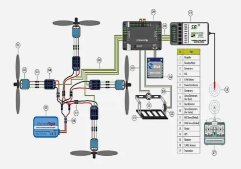
Figure 1 : Block Diagram of System
II.
LITERATURE SURVEYVolume 3, Issue 7, September-October-2018 | http:// ijsrcseit.com
Pranit Barhate et al. Int J S Res CSE & IT. 2018 September-October-2018; 3(7) : 236-238
576
research papers from various quadrotor groups were used as guides in the early development of the
dynamics and control theory.
No Author name Publis-hed Year
Proposed work Result Link
1. MAHEN M.A, carrying out surveillance from 25 meters height for a duration of 15 minutes
Drone\Importa variety of directions since the platform seems to be as flexible as we initially
It implement a control loop for agricultural applications
where UAVs are
responsible for spraying chemicals on crops
III.
METHODS AND MATERIALSYSTEM ARCHITECTURE
CONTROLS :
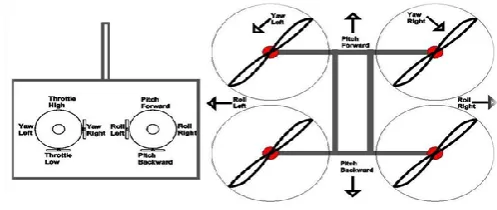
Roll – Done by pushing the right stick to the left or right. Literally rolls the Quad-copter, which maneuvers the Quad-copter left or right.
Pitch – Done by pushing the right stick forwards or backwards. Tilts the Quad-copter, which maneuvers the Quad-copter forwards or backwards.
Yaw – Done by pushing the left stick to the left or to the right. Rotates the Quad-copter left or right. Points the front of the copter different directions and helps with changing directions while flying. Throttle – Engaged by pushing the left stick forwards. Disengaged by pulling the left stick backwards. This adjusts the altitude, or height, of the Quad-copter.
Trim – Buttons on the remote control that help you adjust roll, pitch, yaw, and throttle if they are off balance.
The Rudder – You might hear this term thrown around, but it’s the same as the left stick. However, it relates directly to controlling yaw (as opposed to the throttle).
Aileron – Same as the right stick. However, it relates directly to controlling roll (left and right movement).
The Elevator – Same as the right stick. However, it relates directly to controlling pitch (forwards and backwards movement).
Bank turn – A consistent circular turn in either the clockwise or counterclockwise direction.
Hovering – Staying in the same position while airborne. Done by controlling the throttle
Figure 1 : Simple sketch of roll, pitch, yaw, and throttle on a transmitter and Quad-copter
Figure 2 : Simple sketch of roll, pitch, yaw, and throttle on a transmitter and Quad-copter
Frame principle : Frame is the structure that holds all the components together. The Frame should be rigid, and be able to minimize the vibrations coming from the motors. Quad-copter frame consists of two to three parts which don’t necessarily have to be of the same material:
The center plate where the electronics are mounted
Four arms mounted to the center plate
Four motor brackets connecting the motors to the end of the arms
Most available materials for the frame are:
Carbon Fiber, Aluminum
Volume 3, Issue 7, September-October-2018 | http:// ijsrcseit.com
Pranit Barhate et al. Int J S Res CSE & IT. 2018 September-October-2018; 3(7) : 236-238
237
TAKE OFF MOTION
LANDING MOTION
IV.
RESULTS AND DISCUSSIONResult Analysis –
After configuring all the parts, assembling as required, configuring Software, finally we obtained our Quad-copter which is shown below. We need to test the Acceleration Calibration every time when we change the ground surface area.
V.
CONCLUSIONAs per the design specifications, the quad copter self stabilizes using the array of sensors integrated on it. It attains an appropriate lift and provides surveillance of the terrain through the camera mounted on it. It acts appropriately to the user specified commands given via a remote controller .Its purpose is to provide real time audio/video transmission from areas which are physically in-accessible by humans.
Thus, its functionality is monitored under human supervision, henceforth being beneficial towards military applications. It is easy to manoeuvre, thereby providing flexibility in its movement. It can be used to provide surveillance at night through the usage of infrared cameras. The system can further be enhanced for future prospects. The GPS data logger on the Quad-copter stores its current latitude, longitude, and altitude in a comma separated value file format and can be used for mapping purposes.
VI.
FUTURE SCOPEFuture of a quad-copter is quite vast based on various application fields it can be applied to. Quad-copter can be used for conducting rescue operations where it’s humanly impossible to reach. In terms of its military applications it can be more widely used for surveillance purposes, without risking a human life.
VII.
REFERENCES[1]. Hoffmann, G.M.; Rajnarayan, D.G., Waslander, S.L., Dostal, D., Jang, J.S., and Tomlin, C.J. (November 2004). "The Stanford Test bed of Autonomous Rotorcraft for Multi Agent Control (STARMAC)"
[2]. Leishman, J.G. (2000). Principles of Helicopter Aerodynamics. New York, NY: Cambridge University Press. Technology .NASA
[3]. Anderson, S.B. (1997). "Historical Overview of V/STOL Aircraft Technical Memorandum 81280. Quad-
[4]. Pounds, P.; Mahony, R., Corke, P. (December 2006). "Modelling and Control of a Rotor Robot".