Western University Western University
Scholarship@Western
Scholarship@Western
Electronic Thesis and Dissertation Repository
12-6-2012 12:00 AM
Development and Evaluation of a Real-Time Framework for a
Development and Evaluation of a Real-Time Framework for a
Portable Assistive Hearing Device
Portable Assistive Hearing Device
Aleksandar Dimitrov Mihaylov
The University of Western Ontario
Supervisor Vijay Parsa
The University of Western Ontario
Graduate Program in Electrical and Computer Engineering
A thesis submitted in partial fulfillment of the requirements for the degree in Master of Engineering Science
© Aleksandar Dimitrov Mihaylov 2012
Follow this and additional works at: https://ir.lib.uwo.ca/etd
Part of the Signal Processing Commons
Recommended Citation Recommended Citation
Mihaylov, Aleksandar Dimitrov, "Development and Evaluation of a Real-Time Framework for a Portable Assistive Hearing Device" (2012). Electronic Thesis and Dissertation Repository. 980.
https://ir.lib.uwo.ca/etd/980
This Dissertation/Thesis is brought to you for free and open access by Scholarship@Western. It has been accepted for inclusion in Electronic Thesis and Dissertation Repository by an authorized administrator of
(Thesis format: Monograph)
by
Aleksandar Mihaylov
Graduate Program in
Enginering Science
Electrical And Computer Engineering
A thesis submitted in partial fulfillment
of the requirements for the degree of
Masters of Engineering Science
The School of Graduate and Postdoctoral Studies
The University of Western Ontario
London, Ontario, Canada
c
THE UNIVERSITY OF WESTERN ONTARIO
School of Graduate and Postdoctoral Studies
CERTIFICATE OF EXAMINATION
Supervisor:
. . . . Dr. Vijay Parsa
Examiners:
. . . . Dr. E. Macpherson
. . . . Dr. I. Polushin
. . . . Dr. R. K. Rao
The thesis by
Aleksandar Dimitrov Mihaylov
entitled:
DEVELOPMENT AND EVALUATION OF A REAL-TIME FRAMEWORK FOR A PORTABLE ASSISTIVE HEARING DEVICE
is accepted in partial fulfillment of the requirements for the degree of Masters of Engineering Science
. . . . Date
. . . .
Chair of the Thesis Examination Board
First and foremost I would like thank my supervisor, Dr. Vijay Parsa for allowing me to take
part in this project, for providing crucial guidance and for his endless patience during the work
described herein and for being a great teacher.
I would like to thank my thesis examination panel: Dr. Raveendra Rao, Dr Ewan
Machper-son and Dr Ilia Polushin for taking the time to read and evaluate my work.
Special thanks to Maggie Sazio for all the endless nights spent on this thesis and many
aspects of it. Thank you for your support.
Many thanks to Steve Beulac, who made it possible for me to realize my dream of learning
Linux inside and out. For all of his suggestions and help during development and for all the
random chats we had.
Thanks to my father Dimitar Mihaylov, for all of the relevant talks we have had, thank you
also for the all the other irrelevant and amusing conversation that helped to keep me sane.
Thanks to Tobias Hertzke from Horetech, Germany for all his help with the MHA platform.
Finally thank you to all of my engineering friends and colleagues: Nazanin Pourmand,
Julie Ledges, Ben Morgan, John Pietrobon, Arvind Venkatasubramanian, Filip Aleksanderek,
Gregory Kish and many others. They have helped shape: me, my knowledge and my skills to
what they are today.
Abstract
Testing and verification of digital hearing aid devices, and the embedded software and
algorithms can prove to be a challenging task especially taking into account time-to-market
considerations. This thesis describes a PC based, real-time, highly configurable framework for
the evaluation of audio algorithms. Implementation of audio processing algorithms on such
a platform can provide hearing aid designers and manufacturers the ability to test new and
existing processing techniques and collect data about their performance in real-life situations,
and without the need to develop a prototype device.
The platform is based on the Eurotech Catalyst development kit and the Fedora Linux OS,
and it utilizes the JACK audio engine to facilitate reliable real-time performance
Additionally, we demonstrate the capabilities of this platform by implementing an audio
processing chain targeted at improving speech intelligibility for people suffering from auditory
neuropathy. Evaluation is performed for both noisy and noise-free environments. Subjective
evaluation of the results, using normal hearing listeners and an auditory neuropathy simulator,
demonstrates improvement in some conditions.
Keywords: Intel high definition audio (Intel HDA), audio hardware design, Linux, JACK, Real-time processing, digital signal processing, envelope enhancement, noise reduction, voice activity detection.
Certificate of Examination ii
Abstract iv
List of Figures viii
List of Tables x
List of Appendices xi
Nomenclature xii
1 Introduction 1
1.1 Human Hearing . . . 1
1.2 Auditory Neuropathy . . . 3
1.3 Portable Hearing Aid Systems . . . 5
1.4 Thesis Scope and Problem Statement . . . 7
1.5 Proposed Solution . . . 8
1.6 Thesis Organization . . . 9
2 Literature Review and Background Information 11 2.1 Introduction . . . 11
2.2 Portable DSP systems . . . 11
2.3 Master Hearing Aid (MHA) . . . 14
2.4 Eurotech Catalyst . . . 16
2.4.1 Description of the CPU Module and Development Kit . . . 16
2.4.2 Audio Interface Alternatives . . . 18
2.4.3 Audio Interface . . . 19
2.5 Intel High Definition Audio - Azalia . . . 20
2.5.1 Introduction . . . 20
2.5.2 Controller and Bus/Link Description . . . 21
2.5.3 Codecs, Nodes and Widgets . . . 22
2.6 ALSA - Advanced Linux Sound Architecture . . . 24
2.7 Real-Time Engine . . . 24
2.7.1 JACK Audio Connection Kit . . . 25
2.7.2 MHA and JACK . . . 25
2.8 Considerations for Real-Time Algorithm Design . . . 26
2.8.1 Interrupt and processing Latency . . . 27
2.8.2 Frame Based DSP . . . 28
2.8.3 Execution Time and Memory Limitations . . . 28
2.9 Real-Time Considerations and Hardware Summary . . . 29
2.10 Envelope Enhancement . . . 30
2.10.1 Principles . . . 30
Hilbert Envelope Detection . . . 31
Full-Wave Rectification . . . 32
Enhancing the Envelope . . . 32
2.10.2 Real-Time Implementations of Envelope Enhancement . . . 34
2.11 logMMSE Noise Cancellation . . . 35
2.11.1 Principles . . . 35
2.11.2 Real-Time Implementations of logMMSE . . . 38
2.12 Auditory Neuropathy Simulator . . . 38
2.13 Summary . . . 39
3 Design and Implementation of a Custom Audio Interface 40 3.1 Introduction . . . 40
3.2 Design and Implementation . . . 40
3.2.1 Bandwidth Requirements . . . 41
3.2.2 Power Consumption . . . 41
3.3 Circuit Complexity based on Audio Bus Selection . . . 42
3.3.1 HDA Codec Selection . . . 43
3.3.2 PCB considerations and supporting hardware: Grounding, Motherboard Interface and Power Supply Stabilization . . . 44
3.3.3 Input/Output Stages . . . 45
3.4 Final PCB implementation . . . 45
3.5 Driver Design . . . 47
3.5.1 Intel HDA ALSA driver add-on . . . 47
3.5.2 Widget Configuration and Initialization . . . 48
3.5.3 Audio Widget and Stream Controls . . . 48
3.6 DMA Limitations of the Eurotech Kit . . . 50
3.7 Summary . . . 51
4 Real-Time Framework and Algorithms 52 4.1 Operating system . . . 52
4.1.1 Basic Real-Time Scheduling . . . 53
4.1.2 RTOS kernel and configuration . . . 53
4.1.3 Required Libraries . . . 54
4.1.4 JACK server setup . . . 55
4.1.5 JACK client Description . . . 56
4.2 RT Implementation Considerations . . . 56
4.2.1 Memory and Computational Limitations . . . 57
4.2.2 Automatic Gain Control (AGC) . . . 58
4.2.3 Filtering Objects . . . 59
4.3.1 Envelope Enhancement . . . 61
Pre-Processing . . . 62
Envelope Extraction . . . 63
Envelope Expansion/Compression . . . 65
Output Reconstruction . . . 65
4.3.2 logMMSE . . . 66
Pre-Processing . . . 67
Applying LogMMSE . . . 67
Output Reconstruction . . . 68
4.3.3 Algorithm Tester . . . 69
4.4 Real-Time framework . . . 70
4.5 Summary . . . 70
5 Hardware, Framework and Algorithm Evaluation 72 5.1 Audio Interface Parameters . . . 72
5.2 Framework Performance and Requirements Verification . . . 73
5.3 Speech Shaped Noise . . . 75
5.4 Subjective Validation . . . 77
5.4.1 Stimuli, Pre-processing and Test Set Composition . . . 78
5.4.2 Methodology . . . 78
5.4.3 Results and Discussion . . . 80
5.5 Summary . . . 81
6 Conclusions and Future Work 83 6.1 Summary . . . 83
6.2 Major Contributions . . . 84
6.3 Future Work . . . 85
Bibliography 86 A SVM Classification 91 B HDA Pin Configuration and Verb Table 98 B.1 Pin/Port Configuration . . . 98
B.2 Initialization Verb table . . . 99
C Software Libraries 100 C.1 Intel Performance Primitives(IPP) . . . 100
C.1.1 Introduction . . . 100
C.1.2 Hardware and Software Requirements . . . 101
C.2 GTK and Glade . . . 101
C.2.1 Provided GUI Widgets . . . 101
Curriculum Vitae 103
List of Figures
1.1 Anatomy of the human ear . . . 1
1.2 Generic PDA based algorithm platform . . . 6
2.1 Layered structure of the master hearing aid . . . 14
2.2 PHS prototype based on the Asus Eee PC . . . 16
2.3 Catalyst Module . . . 17
2.4 Catalyst Development Kit . . . 17
2.5 Intel HD Audio Components . . . 20
2.6 Intel HDA controller DMA engines . . . 21
2.7 Intel HDA bus signals . . . 22
2.8 Intel HDA Codec node/widget hierarchy . . . 23
2.9 JACK, ALSA and Kernel Interaction Diagram . . . 26
3.1 Power Supply Stabilization . . . 45
3.2 Headphone/Speaker Interface . . . 45
3.3 Microphone Interface . . . 46
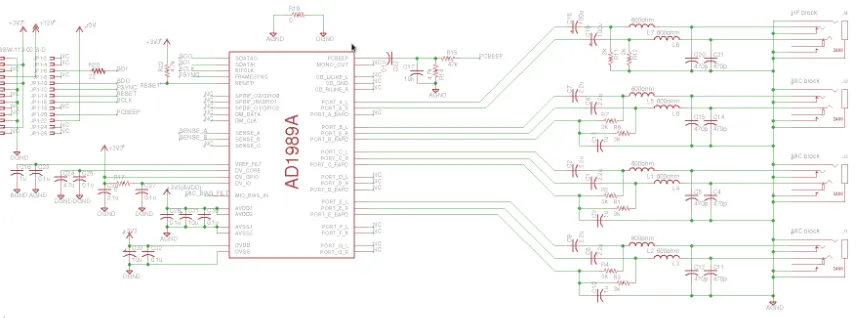
3.4 Circuit Schematic for the AD1989a codec, including supporting hardware . . . 46
3.5 PCB layout bottom copper layer . . . 46
3.6 PCB layout bottom copper layer . . . 46
3.7 Complete AD1989a prototype . . . 47
3.8 Widget Diagram. Red lines show the active signal paths . . . 49
3.9 Alsamixer TUI displaying the exposed audio stream controls for the AD1989 codec . . . 50
4.1 Generic JACK client structure . . . 56
4.2 AGC topology using arbitrary length memory buffers. . . 59
4.3 Envelope Enhancement algorithm flow. Note buffer alignment trick allowing us to simulate non-causal filtering. Short buffers act as a unit frame delay. . . . 62
4.4 Band and envelope waveforms for the sentence ’A boy fell from the window’. . 64
4.5 Envelope Enhancement: Input(top) and Output(bottom) waveforms for the sen-tence ’A boy fell from the window’ . . . 65
4.6 logMMSE algorithm, data flow diagram. . . 66
4.7 Input and Output waveforms for the MMSE algorithm for the sentence ’The birch canoe slid on the smooth planks’ at 5dB SNR. Left: input; Right: output . 68 4.8 GUI for the MMSE client . . . 68
4.9 GUI for the EE client . . . 68
4.10 Block Diagram for the Algorithm tester . . . 69
4.13 Sample algorithm chain including the MMSE and EE clients . . . 71
5.1 Sample speech-shaped noise spectrum . . . 76 5.2 Processing of the sentence ’Smoke poured out of every crack’ . . . 77 5.3 Envelope Enhancement Subjective Results for clean speech at two strengths of
the EE algorithms . . . 80 5.4 Envelope Enhancement Subjective Results for noisy speech at 5dB SNR . . . . 81 5.5 Envelope Enhancement Subjective Results for noisy speech at 10dB SNR . . . 82
A.1 Scatter plot forΛ6andΛ7 . . . 95 A.2 VAD decisions for a single speech segment from the training set. SNR=5dB . . 97 A.3 VAD decisions for a single speech segment from the training set. SNR=20dB . 97
List of Tables
2.1 Parameter values used to simulate various AN conditions . . . 39
3.1 Bandwidth requirements for common stream formats, given in bytes . . . 41
3.2 Audio interfaces power consumption . . . 41
4.1 Library and software versions used in the framework . . . 55
4.2 I/O Latency for various JACK server setups . . . 55
5.1 Measured audio interface parameters . . . 73
5.2 Measured Latency for Various Processing Schemes . . . 74
A.1 Error rates of GM and SVM based VAD for various SNR conditons, compared to values reported in original study . . . 96
B.1 Port Configurations . . . 98
B.2 Verb Sequence Configuring the AD1989 to the required specifications . . . 99
Appendix A: SVM Classification . . . 91 Appendix B: HDA Pin Configuration and Verb Table . . . 98 Appendix C: Software Libraries . . . 100
Nomenclature
ABR Auditory Brainstem Response
ADC Analog to Digital Converter
ALSA Advanced Linux Sound Architecture
AN Auditory Neuropathy
API Application Programming Interface
BAHA Bone Anchored Hearing Aid
BPF Band-Pass Filter
CASLPA Canadian Association of Speech Language Pathologists
and Audiologists
CPU Central Processing Unit
DAC Digital to Analog Converter
dBFS dB level relative to maximum output before clipping
dBu RMS Voltage level relative to
√
6VRMS
DSP Digital Signal Processor/Processing
EE Envelope enhancement
FFT Fast Fourier Transform
FIR Finite Impulse Response
GPP General Purpose Processor
GUI Graphical User Interface
HPF High-Pass Filter
I/O Input/Output
IC Integrated Circuit
IIR Infinite Impulse Response
IPP Intel Performance Primitives
IRQ Interrupt Request
ISR Interupt Service Routine
LDO Low Drop-Out
LPF Low-Pass Filter
MHA Master Hearing Aid
MMU Memory Management Unit
MSI Message-Signaled Interrupt
OAE Otoacoustic Emission
OO Object-oriented programming paradigm
OS Operating System
PC Personal Computer/Desktop Computer
PCB Printed Circuit Board
PDA Personal Digital Assistant
PHS Personal Hearing System
RT Real-Time
RTE Real-Time Engine
RTOS Real-Time Operating System
SVM Support-Vector Machine
TUI Text-based User Interface
VAD Voice-Activity Detector
Chapter 1
Introduction
1.1
Human Hearing
Human hearing involves the perception of acoustic vibrations through the auditory system.
Figure 1.1 illustrates the structure of human ear, which is composed of outer, middle and inner
ears, as well as the central auditory nervous system.
Figure 1.1: Anatomy of the human ear [1]
The outer ear consists of the pinna and the external auditory canal which terminates at the
tympanic membrane. The acoustic signals channel through the auditory canal and impinge on
the tympanic membrane, setting it in vibration. The tympanic membrane is connected to three
bones that constitute the middle ear: malleus, incus and stapes. This arrangement of the middle
ear bones enables efficient transfer of acoustic energy to the inner ear. The inner ear can be
divided into three parts: the semicircular canals, the vestibule and the cochlea. The cochlea
is a spiral-shaped structure filled with fluid. The fluid is set in motion by the vibration of the
stapes, which in turn excites the hair cells contained within the cochlea. The resulting electrical
signals are combined in the auditory nerve and transmitted to the auditory cortex through the
brainstem, where it is interpreted.
A number of factors can lead to abnormalities in the auditory system which in turn can
lead to hearing loss or deafness. According to the Canadian Association of Speech Language
Pathologists and Audiologists (CASLPA), hearing loss is the third most common chronic
dis-ability among older adults, after arthritis and hypertension [2]. The incidence rate of hearing
loss increases with age; approximately 10% of the general population are estimated to suffer
from some form of hearing loss, but this statistic increases to 20% for the part of the population
over 65, and 40% for those over 75[2]. Comprehensive assessment of auditory function and
appropriate prescription and fitting of a hearing device are crucial for enhancing the
commu-nicative ability and restoring good quality of life for the affected persons.
Hearing loss has traditionally been classified into conductive and sensorineural types:
• Conductive hearing loss occurs when sound is not transmitted properly due to abnormal
functioning of the outer or middle ear [3]. A treatment approach to compensate
conduc-tive hearing loss is the utilization of bone anchored hearing aids (BAHAs). A BAHA
includes a titanium implant that is surgically inserted into the temporal bone and
con-nected to a sound processor through an external abutment. The sound processor converts
the acoustic signal inputs into mechanical vibrations of the implant, which travel through
the temporal bone and directly excite the cochlea.
• Sensorineural hearing loss is the most common form of hearing loss, which occurs when
1.2. AN 3
abnormally [3]. Persons with sensorineural hearing loss can be rehabilitated through the
use of properly tuned and fitted hearing aids.
In addition to the hearing loss caused by malfunctioning peripheral auditory system,
dis-orders in central auditory processing can also cause abnormal hearing. Auditory neuropathy
is one such disorder, which is characterized by normal or near-normal cochlear function, but
abnormal auditory nerve responses [4].
1.2
Auditory Neuropathy
Auditory neuropathy (AN) is a hearing disorder that affects the timing of neural activity in
the auditory pathway and therefore disrupts temporal aspects of auditory perception [5]. As
alluded to earlier, the most common type of hearing loss, sensorineural hearing loss, is caused
by damage to the outer hair cells. In contrast, AN can result from damage to the inner hair
cells, the synapse between the inner hair cells and the auditory nerve, and/or the auditory
nerve or brainstem pathways. Individuals afflicted with AN typically exhibit the following
characteristics: elevated thresholds on pure-tone audiogram by air and bone conduction, poor
understanding of speech in noisy surroundings, absence of the acoustic reflex response in any
configuration for any stimuli, and no auditory brainstem response (ABR) to acoustic stimuli
above their detection threshold [4].
Few options exist for rehabilitating patients suffering from AN. Conflicting results are
re-ported over the use of conventional hearing aids for people with AN. Although some studies
have shown that 50% of affected children benefit from conventional amplification hearing aids,
others have shown detrimental effects, including loss of otoacoustic emissions (OAEs) (some
without any change in pure-tone sensitivity) and permanent threshold shifts [6].
Cochlear implants include surgically implanted array of electrodes into the cochlea, which
directly stimulate the auditory nerve. As such, this device circumvents improper functioning
impaired people, it does have its own set of drawbacks including high cost, standard surgical
risks, and potential loss of residual hearing due to surgical implantation. Moreover, evidence
is mixed on the effectiveness of cochlear implants as a rehabilitation option for AN patients.
Some studies have shown considerable speech perception improvement, while others did not
[7].
Evidence does exist that alternative signal processing algorithms can be effective in
im-proving speech perception by AN patients. For example, temporal envelope enhancement
al-gorithms, which exaggerate the temporal peaks and valleys of a speech signal, have shown
promising results in AN patients [5, 8, 9]. However, these algorithms are not currently
imple-mented in hearing aids, nor are they tested for their real-time (RT) performance.
The algorithms developed for this thesis were focused on this particular group, as current
treatment methods are limited to conventional amplification or cochlear implantation. In either
case the exact effect of treatment is not well understood. Development of custom
process-ing chain for the condition can therefore greatly benefit patient that suffer from it, either by
modeling the disease’s effect on speech and correcting for it or providing further insight for
clinicians.
In summary, hearing loss afflicts a significant proportion of the human population. To
im-prove communication for these affected people, much research and effort has been put toward
assistive listening devices. These devices range from ear and body-worn hearing aids to bone
anchored hearing aids and cochlear implants, and have achieved significant results for many
different types and severities of hearing disorders. However, the algorithms required to assist
patients with certain disorders (such as AN) are not available in commercial hearing aids, and
in other cases such algorithms have requirements that are too high for the computational and
memory abilities of current hearing aids. This necessitates the development of new assistive
1.3. PHAS 5
1.3
Portable Hearing Aid Systems
Digital signal processing (DSP) finds application in many devices such as: telephones, recorders,
equalizers, hearing aids, etc. Digital signal processors as well as general purpose processors
(GPP) nowadays provide much more processing power than their predecessors. Specialized
hardware solutions are as attractive as ever, and provide functionality as well as superior
per-formance. However, GPPs have also improved in performance, and combined with highly
customizable operating systems (OS) allow for the development of a real-time embedded DSP
framework for audio processing among other things.
Custom hardware solutions provide many advantages such as: high processing speed,
min-imized power consumption, and low costs in mass production. However, every re-design of
a custom-made integrated circuit (IC) or printed circuit board (PCB) is a very cost and time
consuming undertaking. That is, the algorithm to be realized ought to be tested thoroughly
in computer simulations prior to implementing it on a specific custom solution. Additionally
GPP implementations are capable of providing comparable performance with significantly less
effort related to the design and implementation of a complete system. The drawback of GPP
implementations is the trade-offbetween speed of development and power consumption and
efficiency, as well as limited scalability of the finished product/prototype.
Real-time implementation of audio processing algorithms on GPP systems can provide
hearing aid designers and manufacturers the ability to test new processing techniques in-vivo.
Testing and verification of such techniques will thus require less system design effort and
in-volvement from the algorithm designer, and produce a product that can be easily transferred to
other similar systems/platforms. Generally speaking, testing and verification of digital hearing
aid devices and the embedded software and algorithms requires the production of a
proto-type deice. Such devices are often limited in their ability to control various parameters of the
recording/playback process: sample rate, data bit-depth and latency limits, as well as the
pa-rameters of the embedded DSP algorithms. In this study, the focus is on developing and testing
deployment of highly flexible audio DSP algorithms.
Finalized, such a platform will be similar to body-worn hearing aids. However, thanks to
the advancement in processor and memory technology, such a platform can be designed to
be faster and capable of handling wider design constraints (computational complexity limits,
memory footprint bounds, etc). To further improve the usability of this platform in real-life
situations and facilitate flexibility in the embedded algorithms, the system should provide an
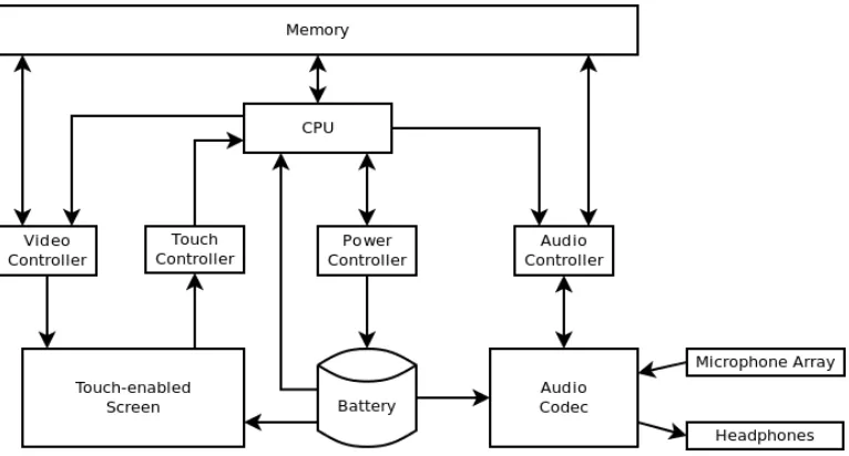
intuitive user interface while maintaining a small form factor. A simplified block diagram
of the required components is given in Figure 1.2. It must be noted that this thesis is solely
concerned with the development, testing and verification of the audio subsystem as well as the
real-time implementation of audio processing algorithms targeted to the AN population. The
rest of the required components are provided by the development kit used in this thesis, details
of which are given in the next section.
Figure 1.2: Generic PDA based algorithm platform
Many acoustical signal processing algorithms can be reliably judged only by critical
sub-jective evaluation by human subjects. Thus, the simulations should be run in real-time, with
realistic input signals. Moreover, it should be possible to alter the algorithm easily in order
to optimize its performance without the need for complex and extensive modifications of the
1.4. TS PS 7
fields (e.g. conversation in a street with fluctuating traffic noises), the simulation device should
be at least as non-intrusive and portable as the desired end product.
In order for such a platform to be well received and useful to the hearing-impaired
commu-nity as well as the hearing aid developers, steps must be taken to improve user experience as
well as hardware capability.
1.4
Thesis Scope and Problem Statement
The final goal of this project is to develop a portable, mobile platform that will allow hearing
aid users to test and evaluate various hearing aid algorithms in real-life environments. Such
a platform requires several stages of design, and can be generally split into two streams of
implementation: hardware and software.
The hardware side of the project includes the specification and implementation of the
var-ious interfaces such as audio, video and input devices, as well as power supply system and
connectivity (TCP, WIFI, USB, etc.). The imposed hardware design constraints relevant to the
development of an audio interface for such a platform are:
• 6 mono input channels and 2 mono output channels
• Minimum sampling rate of 22kHz
• At least 16bit sample resolution
• Synchronous capture mode
• Matched input stages to ensure equalized performance
• Low power consumption, including sleep capabilities.
The software side includes the design and implementation of the required interface drivers,
to reliable performance, as well as usability in real life situations is robust and predictable
real-time operation. To achieve this goal we focus part of this thesis on the selection and
configuration of a reliable real-time engine (RTE).
Once the hardware was developed and the required software implemented and configured
accordingly, several algorithms were implemented on top of this framework as a proof of
con-cept and to test for the common RT metrics: latency, memory consumption and service
perfor-mance.
1.5
Proposed Solution
The goal of this project is to develop a multi-channel audio capture and playback interface.
Due to the nature of most algorithms and audio enchantment techniques used in today’s
hear-ing aids, multiple channels of synchronized audio input must be available. This would allow
for the development of direction based audio algorithms such as beam-forming and source
localization.
The core of the system is the Eurotech XL Catalyst Module (1GB RAM and 1.2GHz Intel
Atom Z530), which provides comparable performance to most hand-held devices available on
the market such as: cellphones, PDAs, etc. The platform implements most of the hardware
interfaces and components required by a portable device.
The audio interface for this study is based on the Intel HDA standard and was designed
around, and a prototype developed using the AD1989 HDA codec from Conexant. Using
the AD1989 codec allowed us to have up to three stereo, simultaneously sampled recording
channels, and 1 stereo playback channel. The hardware is housed on the Eurotech development
kit[10].
For the purposes of this thesis, the focus was on the audio interface and the rest of the
hardware interfaces are left as provided by the development kit. For a fully portable system
1.6. TO 9
The software layer introduces the Fedora Linux operating system as a RT capable OS with
custom developed device drivers. Reliable RT operation is provided by the Jack Audio
Con-nection Kit (JACK)[11]. The modified Eurotech hardware is configured to allow reliable and
deterministic RT performance. Additionally, the OS kernel is modified to minimize
unneces-sary modules and drivers and enable full pre-emption (in stock kernels the model is voluntary
preemption, which introduces non-deterministic jitter between frames). JACK serves as the
RT engine for audio processing, and it also provides a powerful abstract interface to the audio
hardware.
This framework was then used for the development and validation of audio DSP algorithms,
limited in our case to: envelope enhancement, Ephraim and Malah’s logMMSE noise
suppres-sion and a support-vector machine based (SVM) voice-activity detector (VAD). The algorithms
were implemented as JACK clients as is described further in this thesis. Computational
com-plexity of audio DSP algorithms was addressed by using Intel’s performance primitives library
(IPP) (see Appendix C).
1.6
Thesis Organization
• Chapter 2 contains the literature review and background information. Description is
given of currently available portable DSP systems and in particular the Master hearing
aid (MHA) development platform. Details of the hardware and software used in the
development of the prototype platform are presented. Presented is a review of the
prin-ciples behind noise reduction and envelope enhancement algorithms as well as their RT
implementations.
• Chapter 3 contains details of the design and implementation of a custom audio interface.
Outlined are the objectives used in the design the audio interface. Interfacing options
for audio data streaming with the development kit are explored and finally, details of the
• Chapter 4 explains the use and configuration of the RT framework as well as the RT
implementation methodology used in deploying the algorithms given in chapter 2.
• Chapter 5 demonstrates the performance characteristics of the developed custom audio
interface, RT framework and deployed algorithms. Parameters of the developed audio
interface are validated against numerical values discovered in literature. Algorithm
per-formance is validated using a pilot subjective study with normal hearing subjects.
• Chapter 6 contains the conclusions drawn from the work on this thesis. Results of study
are stated, areas for future development are suggested and the major contributions of the
Chapter 2
Literature Review and Background
Information
2.1
Introduction
The goal of this chapter is to review the literature surrounding the key areas within the realm of
this thesis, and to present background information required for system design and
implemen-tation. Current state-of-the-art in portable DSP systems targeted for assistive hearing device
application are reviewed first. A description of the development platform chosen for this project
and the issues surrounding it are presented. This is followed by a technical description of the
two algorithms intended for real-time implementation and use by AN patients.
2.2
Portable DSP systems
Portable hearing aid simulators and general purpose DSP platforms are an active area of
re-search, as the benefits that can be gained from such systems are great, especially for people
with certain types of hearing loss as well as for people developing, validating and evaluating
hearing aid algorithms and their respective configurations configurations.
A systematic review of the literature shows that the existing solutions for portable hearing
systems are either PC-based DSP platforms capable of high audio data throughput or PDA
or cellphone based DSP platforms that are more portable but harder to program and
config-ure. Moreover the smaller form factor device implementations (such as cellphones, PDA and
tablets) suffer from the lack of a floating point processor on board, which creates
program-ming challenges. Lastly, there are the so called “full-custom” implementations that are built
to function as stand-alone hearing aid simulators, however in most cases such devices do not
provide for user interactivity, do not offer platform and algorithm flexibility (flexibility here
refers to the ability to modify the signal flow-path and algorithm parameters during the use of
the device) and/or require a large time and resource investment in their development. Some of
the more recent developments in the field of portable hearing assistive devices are summarized
below:
• A RT platform for general audio DSP algorithm evaluation was described by
Mago-tral and Stetzler in [12, 13]. The platform was capable of processing two input speech
channels at a sampling rate of 32 kHz and driving a stereo headphone output. It provided
algorithms for frequency shaping, noise suppression, multi-band amplitude compression,
and frequency dependent interaural time delay algorithms.
• A high performance system based on the signal processor Motorola DSP56309 was
de-scribed by Rass et. al. in [14]. The device included high quality external stereo ADCs
and DACs with 20 bit word length each. The reported dynamic range exceeded 88 dB.
User interactivity is limited to adjusting the input/output gains using digitally controlled
potentiometers. The authors developed a software fitting suite that was accessed from
an external PC, and used to adjust the parameters of the underlying algorithms. A set of
software tools and configurable assembler code modules implemented all hardware
de-pendent software routines. The authors demonstrated that such a device can be a helpful
means for development and field evaluations of advanced new hearing aid algorithms.
A few years after the original publication the authors came forward with a more
2.2. PDSP 13
embedded in a complete stand-alone system[15].
• A general purpose personal computer (PC) was employed by Kruger et.al. in [16] as
a DSP testing platform. The goal of the study was to separate hardware and algorithm
related programming issues in order to liberate the designer from problems which are
not related to the development of the algorithm. The authors employed a commercial
PC (Pentium IV, 1800 MHz) to implement an acoustic echo control unit with two input
and two output channels. The system was capable of a sampling rates ranging from 8 to
32kHz.
• Grimm et.al. in [17, 18] developed a more portable, user friendly and flexible platform
as compared to [15]. The authors employed a netbook computer with a dedicated audio
interface in combination with a mobile phone as the development platform (see Figure
2.2). They reported a dynamic range of over 90dB for two and six input channel setups. It
was shown that the prototype system can integrate hearing aid functionality, telephony,
public announcement systems, and home entertainment. An example binaural speech
enhancement scheme that represents a large class of possible personal hearing system
(PHS) processing schemes was shown to be compatible with the general concept.
Algo-rithm deployment was done using the Master Hearing Aid framework that is discussed
in detail below.
• The authors in [19] presented a wavelet-based speech coding strategy for cochlear
im-plants, with an RT implementation on a personal digital assistant (PDA). The system
only allowed for a single channel cochlear implant and the corresponding microphone.
The authors demonstrated that the proposed strategy achieves higher analysis rates than
the existing strategies while being able to run in real-time on a PDA platform. Using
a PDA as host for the user interface allowed users to easily manipulate the parameters
involved in the processing chain and study their effects. The authors reported processing
Programming on a fixed-point DSP platform can be more challenging as compared to
floating-point platforms. Additionally the user interface developed for the PDA was
pro-grammed using hybrid LabVIEW, in order to achieve user interactivity and RT display.
2.3
Master Hearing Aid (MHA)
The H¨orTech Master Hearing Aid is a software development platform for signal processing
algorithms and a software solution of a hearing aid prototype. MHA has a layered structure as
shown in Figure 2.1
Figure 2.1: Layered structure of the master hearing aid[17]
• The audio backbone is external to MHA. It is an abstraction for a source and a sink for
audio data. The MHA can use different audio backbones by selecting the corresponding
MHA IO library. Usable audio backbones are: file system, sound card drivers (Windows
MME, Windows ASIO, Linux ALSA, Linux OSS), JACK low latency sound server and
router, and network audio streams.
• The MHA framework selects the MHA I/O library and passes the fragmented signal to
2.3. MHA(MHA) 15
• An MHA plugin generally performs the signal processing, but plugins for signal flow
management also exist. Each plugin forms one processing block; algorithms can consist
of one or more plugins. MHA plugins communicate with the framework and with other
plugins through a simple ANSI-C interface. Plugins can work on waveform data (time
domain) or short-time Fourier transformed data (frequency domain). Plugins can
im-plement domain translations, e.g. FFT (fast Fourier transform) and iFFT (inverse FFT)
plugins exist.
The MHA software development toolbox contains a number of libraries that facilitate
de-velopment of RT algorithms, provide access to basic signal analysis and modification
proce-dures, and allow access to the configuration space (e.g. GUI configuration interface, MATLAB
access). [17]
To summarize, the MHA platform offers a low-cost alternative to implementing hearing aid
algorithms directly on hearing aids by replacing the digital hearing aid with a standard off
-the-shelf PC. This allows for higher computational complexity algorithms to be deployed without
having to limit their performance based on the overall power consumption and available
com-puting capabilities. Moreover it allows for easy algorithm configuration without the need for
hardware modification. The MHA framework has been previously deployed as a portable
hear-ing aid simulator by Grimm et. al. [18] as shown in Figure 2.2. The authors utilized an Asus
Eee PC and a custom audio interface to facilitate portability and flexibility. The dedicated USB
audio interface was developed to fulfill the requirements of the authors’ PHS prototype. The
audio interface has been developed in two variants: a device with four inputs and two outputs to
drive two audio headsets with two microphones in each headset (USBSC4/2), and a device with
six inputs and two outputs, for two audio headsets with three microphones each (USBSC6/2).
While the MHA offers significant potential and is actively developed and used, during the
pilot stages of this project several issues were identified with the MHA:
• There is no reliable and detailed documentation on the configuration and troubleshooting
Figure 2.2: PHS prototype based on the Asus Eee PC[18]
• The initialization configuration scripts that ship with versions 4.4.27 and prior, are not
executable as is, and require modifications and debugging, making the use of examples
and algorithm chains harder until the user is comfortable with the structure of those files.
• It is not truly portable, as it still requires large hardware. Changes to algorithm
param-eters by a user during field operation are not easy to make, and require modification of
the processing chain configuration files.
• It requires MATLAB to display a control panel GUI; without it configuration and control
of the signal chain can be difficult. However the MHA host does not have to be on the
same platform or even same computer as the MATLAB GUI.
2.4
Eurotech Catalyst
2.4.1
Description of the CPU Module and Development Kit
The work presented in this thesis is based on the Eurotech Catalyst Module. It is an
2.4. EC 17
Intel Atom Z530 along with 1GB of DDR2 RAM, as well as the system control hub (SCH
US15WP). The SCH integrates graphics, memory, and I/O into a small package. Despite the
small form-factor of the Catalyst module (see Figure 2.3) it offers comprehensive I/O and
mul-timedia capabilities including high definition graphics and audio while maximizing the MIPS
to mW ratio and consuming less than 5W of power in high performance mode [10].
The Catalyst module is designed to be an encapsulated embedded module facilitating rapid
prototyping of embedded systems without the need for many additional external hardware
com-ponents. The carrier motherboard is the key component of the Eurotech Catalyst development
kit, and it serves the purpose of extending the capabilities of the Catalyst module, by providing
an ATX style power supply and hardware interfaces for the various data buses and I/O modules
present on the Catalyst module itself. These include the video and audio interfaces, USB host
and client interfaces, memory card readers, networking, etc. Additionally, the kit includes a
touch screen display and controller (see Figure 2.4).
The Catalyst offers further flexibility by supporting several operating system options as
well as some real-time operating systems (RTOS).[10]
2.4.2
Audio Interface Alternatives
Based on the available interfaces on the Catalyst Module[10], several design alternatives are
possible. Nonetheless they all require the same building blocks: ADCs, DACs, data bus and bus
controller as well as external components. Several high-fidelity ADCs and DACs are available
on the market and can be deployed on the target platform utilizing one of the following bus
implementations and controllers:
• PCI: PCI based audio interfaces can either be embedded on the motherboard of the device
or implemented as a slot-in card. Maximum theoretical bandwidth for the PCIexpress
x1 available on the Catalyst module is 300MB/s, with 4 of the 5 available PCI slots
multiplexed through a PCIe switch. Signaling levels on the PCI bus can be either 3.3
or 5V with an average minimum power consumption of 0.3W to 0.5W per PHY layer.
Additional power consumption must be allocated for the ADC and DAC section, as well
as the PCI controller on the Catalyst Module. Data is delivered serially over one lane, due
to hardware constraints on the Catalyst Module[20], which include, but are not limited
to, a single lane of PCI data available on the Eurotech Development Kit [10].
• USB: the USB bus is widely used for various peripherals, among which are sound cards
(audio interfaces). The Catalyst module offers five USB 2.0 ports on a single USB host,
with a maximum bandwidth of 57MB/s at high-speed mode of operation.
Implementa-tion of a USB audio interface will require a bus client such as the TUSB3200 (Intel 8052
based) and an audio codec such as the PCM3794, both from Texas Instruments. The two
devices can be connected through anI2S bus (Inter-IC sound interface), and the required
control signals have to be implemented using the I2C bus (Inter-IC communication
in-terface). For the given example components, power consumption of the codec is 50mW,
and of the USB streaming controller is 200mW, additional supply power will be required
for external components. Data is delivered through the USB host controller serially to
2.4. EC 19
• Intel HDA: Intel High-Definition Audio (Azalia or Intel HDA) is a task specific bus
available on most modern chipsets, and allows for a maximum sample rate of 192kHz, at
a maximum of 32bits/sample. Maximum playback bandwidth is 6MB/s and maximum
capture bandwidth is 3MB/s, both independent of the command interface which uses the
same bus. The distinguishing feature of Intel HDA is the codec, which incorporates the
bus client, ADC and DAC stages, as well as mixers and multiplexers all on the same
IC. Both data and control flow on the same bus line, thus lowering the number of wired
connections required to implement a solution. Power consumption of a typical HDA
codec is dependent on the number of active ADC and DAC pairs and typically ranges
between 150mW to 300mW. Data is delivered serially on the HDA bus and directed to
dedicated DMA engines housed within the south-bridge of the chipset. Unlike USB,
the dedicated nature of the DMA engines guarantees their availability when needed, and
simplifies the device driver development [21].
2.4.3
Audio Interface
As described above, the Catalyst module provides various bus interfaces, many of which can be
used to develop the audio system of the platform. These include PCI,I2S, USB and Intel HDA.
There is an audio system already present on the development kit, built on top of the Intel HDA
interface, and uses an 92HD45 IDT codec. Unfortunately this interface has limited
record-ing capabilities and as such is unsuited for our needs. Therefore, the first step in this thesis
project was to develop a custom audio system, capable of multi-channel synchronous
record-ing. Our system also utilized the HDA bus, however a more advanced codec from Conexant,
the AD1989 was used. The original development of this codec was done by Analog Devices
2.5
Intel High Definition Audio - Azalia
Intel HDA is a high-fidelity audio bus developed for the consumer market. A detailed
de-scription and guidelines for the development of Intel HDA based systems is provided in [22].
Following is a brief summary of the structure of the Intel HD audio link and related
compo-nents, as well as data transmission specifics using the HDA bus.
2.5.1
Introduction
There are three key components to any Intel HDA solution: the Intel HD Audio Controller,
an Intel HD Audio Link, and one or more Intel HD Audio Codecs, as shown in Figure 2.5.
The controller is responsible for communicating audio and control data from the codec to the
CPU and memory through a direct memory access (DMA) engine. The bi-directional link
is the hardware bus along which audio data and commands are exchanged. The codec sends
analog data to physical transducers (i.e. speakers, headphones) and receives analog data from
an attached audio device such as a microphone or a line in connection. It is also responsible
for digital to analog and analog to digital conversion of the audio data which is communicated
along the HDA link.
2.5. IHDA- A 21
Figure 2.6: Intel HDA controller DMA engines[22]
2.5.2
Controller and Bus
/
Link Description
On system start-up (as well as during forced initialization conditions), the HDA controller is
responsible for the discovery and enumeration of all the available codecs on the bus/link. It is
responsible for the relay of instructions and data to and from each codec, and it contains the
Direct Memory Access (DMA) engines which stream audio data to and from the codec (see
Figure 2.6). DMA engines are an efficient method of communicating data between peripheral
devices and the system’s memory without having to go through the CPU and usually DMA
transfers are faster than non-DMA transfers.
The link itself, which connects a controller with one or more codecs, is a multi-wire
electri-cal interface consisting of the BITCLK, SYNCFRAME, and RESET signals. It also contains
one to four SDO signals, denotedS DO0−S DO3respectively, which are used to transmit
play-back data from memory to the codecs. The SDO lines can be multi-point, i.e. a single SDO line
can be attached to multiple codecs. The HDA link contains one to fifteen SDI signals, denoted
S DI0−S DIN, which transfer data from the codecs to memory, through the input DMA engines.
Only one SDI line can be associated with a given codec at a time, thus limiting the maximum
number of codecs associated to a controller to fifteen.
Figure 2.7: Intel HDA bus signals[22]
SDI line to recover the command response if one is available (command responses for some
verbs are not necessary or simply not implemented). Audio data transmission on the SDI lines
happens on the raising edge of the clock, unlike the SDO lines, where the data packets are
double pumped, i.e. on both raising and falling edges of the clock, thus doubling the effective
available bandwidth for playback modes as compared to capture modes using the same audio
stream setup. This process is illustrated in Figure 2.7.
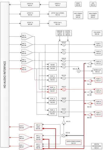
2.5.3
Codecs, Nodes and Widgets
An Intel HDA Codec is modular and its design contains a hierarchy of standardized modules.
The organization and availability of the internal modules varies between codecs. The codec
architecture includes a discovery and addressing scheme that allows for a single driver to easily
support a wide variety of codecs, this however only applies a default configuration which is
inferred from the current structure of the tree hierarchy of codec nodes and may not match the
design intent.
A node is either a single module within a codec or it is a collection of a module and all its
children modules that are connected below it in the hierarchy, as shown in Figure 2.8. Each
node has a unique address, known as a node ID (NID). An NID is usually 7 bits and has a
2.5. IHDA- A 23
Figure 2.8: Intel HDA Codec node/widget hierarchy[22]
targeted at that node.
The root node (NID 0x00) is the node at the top of the hierarchy and serves as a pointer to
the function groups contained in the codec. Even though the HDA specification does not limit
the set of available function groups, currently there are only two supported :modem function
group (MFG) or an audio function group (AFG). This thesis is solely concerned with the AFG,
as it is the only available function group on the considered HDA codecs.
Within each function group node is a collection of modules known as widget nodes or
wid-gets. Widgets can be interconnected different ways, as defined by the codec designer/manufacturer.
This allows support of an arbitrary number of audio input and output channels. Widgets are
either 1-channel (mono) or 2-channel (stereo). An AFG as a whole can support greater than
2-channel sound by using multiple widgets.
Any widget can be connected to more than one other widget. These hard-wired connections
are pre-defined when the codec is designed and are stored in the widget’s connection list. Upon
initialization the driver is responsible for interrogating each widget about its connection list.
Selection of the required connection is achieved by a command verb targeted at the NID of the
widget that contains the list(behaviour inherited from digital multiplexers). The types of standardized audio widgets are:
• Audio Input Converter (ADC) Widget
• Pin Widget
• Mixer Widget
• Selector Widget
• Power Widget
• Volume Knob Widget
• Beep Generator Widget
2.6
ALSA - Advanced Linux Sound Architecture
Advanced Linux Sound Architecture (ALSA) is a free and open source software framework
providing an API for device drivers for sound cards. It provides support for multiple sound card
architectures, and is capable of low-latency performance given the right platform configuration
and capabilities. Additionally ALSA is capable of automatically configuring most common
commercial sound hardware as well as some professional systems. More importantly at the
core of its design lies a well tested error handling mechanism that aids during development of
modules/drivers that are to operate under the framework.
Development of a custom driver for the chosen HDA codec was done within the ALSA API
using the already developed HDA generic driver as a template. This included the configuration
of the codec, power control of the codec and instantiation the required audio controls: mixers,
volume and mute controls.
2.7
Real-Time Engine
Implementing a portable DSP system capable of processing the signals originating withing the
users’ environment and providing near instantaneous results to the user, requires a low-latency
2.7. R-TE 25
not impose large amount of lag between an audio event (such as speech production,
environ-mental sounds, etc) and the users’ perception of the event. Low-latency, as applied to DSP
algorithm modification, should limit the quantity and amplitude of artifacts introduced by the
modification.
For this purpose, Linux is chosen as the real-time operating system. This choice is based
on the ease of customization of the Linux OS, as well as wide availability of know-how on
the topic of DSP in Linux. Additionally optimization of the Linux distribution was required to
allow for real-time performance.
2.7.1
JACK Audio Connection Kit
JACK is an RT audio routing engine capable of high performance, high fidelity operation.
Originally developed for the Linux OS, its authors have developed ports for Mac OS as well
as Windows. JACK comes as an intermediary layer between the hardware driver stack ALSA,
and the DSP algorithm framework developed within this thesis. Interactions between ALSA
and JACK are done in kernel space, thus allowing for efficient memory operations (see Figure
2.9).
The structure of a JACK application and the JACK RT engine allows audio clients to be
connected in an arbitrary length processing chain. The implication is that each DSP algorithm
implemented on the framework can be broken down into sub-processes which can then be
implemented as separate JACK clients, debugged and tested separately.
2.7.2
MHA and JACK
MHA and JACK are not mutually exclusive processing frameworks as noted above. Moreover,
JACK clients can be developed to complement the function of MHA.
• JACK offers better documentation and fewer bugs due to the larger user base and
Figure 2.9: JACK, ALSA and Kernel Interaction Diagram[23]
• Similar plug-in based algorithm implementation is achievable as when using MHA.
• Chaining several algorithm blocks using MHA can be harder, and may require collecting
all the needed blocks into a single plug-in
• Many of the complex algorithm blocks available in MHA are not available in JACK,
and if they are, their performance cannot be compared to the available MHA algorithms
without extensive testing on the target platform.
• As MHA can require JACK for certain tasks, implementing blocks directly in JACK
can simplify the process by eliminating one level of the abstract interface, thus possibly
improving RT performance in low-power devices.
2.8
Considerations for Real-Time Algorithm Design
Implementing DSP algorithms in an RT environment requires special considerations and care
must be taken in order to ensure reliable, artifact free performance. Metrics and evaluation
2.8. C R-TAD 27
2.8.1
Interrupt and processing Latency
Latency, in terms of data acquisition and data propagation is dependent on the OS and driver
layer of the system used as an RT host. The combined interrupt latency is given by:
τIL= τOS +τH (2.1)
WhereτH is the hardware dependent time contributing to interrupt latency which depends
on the interrupt controller on the board as well as the type of the interrupt. τOS is the OS
induced overhead in processing the interrupt. This quantity has a best case and a worst case
scenario worth considering. The best case situation is when only minimal overhead is added
before the interrupt service routine (ISR) starts. The worst case scenario occurs when the kernel
has disabled interrupts to protect critical sections. In this caseτOS is the sum of best case and
the longest interrupt lockout time in the kernel. It should be noted here that this latency applies
to both audio data recording and playback.
Additionally, processing latency comes into play once the acquired audio data has been
delivered to the host memory. Any processing performed on the host computer will introduce
filter and buffering delays. This is also where execution time bottlenecks occur due to the high
computational complexity of the section.
The term sampling latency is used to refer to the combination of data acquisition and data
collection faced when using an RT engine, such as JACK, to gather data. This metric is based on
the size of the buffers used to store incoming and outgoing data, the sample rate and the number
of buffers requested by the JACK client when its processing callback is evoked. Specifically
for JACK this metric can be calculated using (2.2):
τS L=
number o f bu f f ers∗bu f f er size
sample rate (2.2)
This gives the absolute minimum latency that can be encountered when using an audio DSP
delay is given by the addition of the result of (2.2) to the result of (2.1), which is dependent on
the OS configuration and capabilities of the chosen audio interface.
2.8.2
Frame Based DSP
It is obvious that in the RT application of a processing algorithm it will be impossible to access
to all of the audio data including past and present. It is highly unlikely to have close to
un-limited memory in which to store more than a few seconds of previously acquired input data.
Additionally, an algorithm that is to be realized in an RT setting must be causal, obviously
due to the systems inability to predict or acquire any future samples. Moreover, facilitating
audio DSP processing on a limited memory system requires that the algorithm is capable of
“forgetting” older samples, replacing them with the incoming data. Therefore, a frame-based
implementation for the required algorithms must be utilized, i.e. dependence on old samples
should be limited to a specified time window, and long-term information should be stored in
terms of a statistical estimate. For example, noise floor level or harmonic component
ampli-tudes can be remembered in short-time implementations, and in the cases where long-time
information is needed they can be stored in terms of statistical averages, or as in the case of
noise as a mathematical model, incorporating the noise statistics that are changing over time.
2.8.3
Execution Time and Memory Limitations
As Linux is developed to operate on processors equipped with memory management unit
(MMU), this limits the possible choices for a hardware development platform. However JACK
and the rest of the RT framework developed herein can also be run onµCLinux, which is
de-veloped to operate without a MMU [25]. The purpose of a MMU is to provide separation
between running “un-trusted” (user-space) for “trusted“ critical code(kernel space), preventing
user-space memory access errors to result in a kernel crash.
As is the case with any RT and/or embedded system, memory and CPU constraints must
2.9. R-TC HS 29
to be deployed on such a system these constrains vary. The upper bound is always given by
the total system hardware capability. However that can rarely be fully utilized by the audio
DSP processes alone, as any such system requires various miscellaneous tasks that take care of
the system itself. These can include hard-disk/memory monitors and services, networking and
anything else that the designer may deem necessary for the normal system operation.
Memory limitations in DSP arise mostly in situations where the algorithm requires large
amounts of memory for its regular operations, such as long-term data storage or large vector
and matrix operations. This, in the case of audio DSP, is directly related to the length of the
filters used as well as the number of filtering/processing stages that the signal must undergo
from the input to the process to the eventual output of processed data. Additional memory is
often required by the OS to facilitate data transactions between the device driver and user-space
process. In the case of ALSA, all incoming data buffers are located in kernel-space, in order to
protect their contents and read/write rights, and it is the device drivers’ job to copy the buffers
to user-space where applications can access and manipulate the data contained within[26].
2.9
Real-Time Considerations and Hardware Summary
Above a list of important issues regarding the RT framework and supporting hardware were
given. Theses areas must be addressed in the development of the custom RT framework.
Im-portance of CPU utilization and memory management were outlined as they are related to the
operation of the RT engine. Description of the Linux OS and the abstract audio interface layer
provided by ALSA and JACK was given. Additionally, the choice of the Intel HDA bus was
justified for use in the Eurotech development kit. The next sections focus on algorithms
target-ing people with AN, given are details of their theory and some implementations found in the
2.10
Envelope Enhancement
Envelope enhancement (EE) has shown that it can improve word intelligibility scores in
pa-tients with AN[27]. The goal of this part of the thesis is to validate the results given by[27],
and to develop the EE algorithm within the RT framework discussed herein[28, 8, 5]. These
studies have shown an increase in word identification scores when the envelope of the speech
was enhanced. A series of studies utilize EE as a speech enhancement method for speech
corrupted by noise[29, 30].
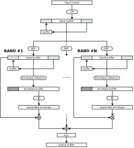
2.10.1
Principles
For either speech enhancement, or to improve ineligibility in patients with AN, EE implements
several common steps. First the input signal is filtered at a frequency lower than the Nyquist
rate of the signal. Then it is split into frequency bands, using one of the following two
ap-proaches:
• Uniform bands: The input signal is split into bands of uniform width (in terms of Hz).
This is the approach utilized in [29, 30], and it takes advantage of the fact that for uniform
bands, finding the Hilbert envelope is equivalent to finding the modulus of the short-time
Fourier transform using a window that spans the range of interest.
• Octave bands: The input signal is split into bands spanning 3rd octave ranges. A given
frequency range is divided into octaves where the upper frequency of each band is twice
the lower frequency of the same band. Third octaves split the octave range further into
three by having the upper frequency limit being 21/3 (1.26) times the lower frequency.
This approach is utilized in [27, 28].
Once the input signal has been split into the corresponding bands the envelopes of the
resulting waveforms are extracted. There are two common methods for envelope detection:
Hilbert Envelope Detector and low-pass full-wave rectification, which when applied to an
2.10. EE 31
Hilbert Envelope Detection
A common and efficient technique used for envelope detection is based on the Hilbert
Trans-form. It involves computing an analytic signal with the real part taken as the original input
signal and the imaginary part is a 90 degree phase shifted version of the input. The required
envelope can then be estimated by taking the magnitude of the resulting complex vector. To
obtain a smooth envelope of the input signal a low pass FIR or IIR filter can be introduced
following the Hilbert transform.
Using the description given in [31] the Hilbert transform of any function f (x) is given by:
F(t)= 1
π
Z ∞
−∞ f(x)
t−xdx (2.3)
The above integral can be evaluated using the Cauchy principle value theorem and it can
be written as the following convolution:
F(t)= 1
πt ? f (x)= F −1F {
f (x)}−
i∗sgn(ω) (2.4)
where using the convolution property of the Fourier transform, the convolution is converted to
a multiplication, andsgn(x) is the sign function.
Having defined the Hilbert transform for an arbitrary real function f(x), construction of the
analytical signal is given by:
Y(t)=y(t)+ jh(t)= A(t)ejω(t) (2.5)
wherey(t) andY(t) are the input signal and analytic signal respectively andh(t) is the Hilbert
transform of y(t) calculated using equation (2.4). Y(t) can then be converted to polar form,
whereA(t) is the envelope of the input signal andω(t) is the phase of the analytic signal, which
can be discarded. In [29, 30] the authors use this approach to calculate the envelopes in their
Full-Wave Rectification
Full-wave rectification is another approach to calculate an envelope of a given input signal.
Depending on the length and type of filters used it often is more computationally intensive
than the Hilbert envelope detector. The Hilbert transofrm method requires one trivial fitering
operation and then a summation accross the input frame to compute the envelope, whereas
full-wave rectification requires taking the absoulte value followed by two filtering stages to
compensate for the filter lag. It is used by [28, 5, 8] for the envelope calculation in an
non-RT implementation of EE. The input signal is split into bands just like above, after which the
absolute value of the signal in each band is passed through a low-pass filter (LPF) with a cutoff
frequency in the range 5-25Hz(corresponding to syllabic rate in human speech). Narne et al.[5]
use a filter with a cutoffat 32Hz, which is the value used in [27] as well. It must be noted that
a review of the literature uncovered that both IIR and FIR filters have been used to implement
full-wave rectification, however for the purpose of EE the phase response, or in particular the
group delay though the filter should be constant, thus facilitating proper reconstruction of the
enhanced signal from the band data.
Enhancing the Envelope
Calculating the enhanced envelope involves multiplying each band signal by a corresponding
band gain vector, derived from the original envelope within each band. The gain equation
relates the original and resulting envelope thorough a non-linear function. Several approaches
for calculating the gain vector were encountered in the literature review:
• Power Law: This is the simplest way of non-linearly enhancing a signal envelope and is
given by Clarkson et.al, as per equation (2.6), wherekindicates the band of interest, yk
is the expanded speech envelope and Ak is the calculated band envelope. It was utilized
in a real-time implementation of the EE algorithm targeted at speech enhancement in
![Figure 2.1: Layered structure of the master hearing aid[17]](https://thumb-us.123doks.com/thumbv2/123dok_us/7784471.1287253/28.612.139.456.286.488/figure-layered-structure-master-hearing-aid.webp)
![Figure 2.2: PHS prototype based on the Asus Eee PC[18]](https://thumb-us.123doks.com/thumbv2/123dok_us/7784471.1287253/30.612.164.426.88.286/figure-phs-prototype-based-asus-eee-pc.webp)
![Figure 2.4: Catalyst Development Kit[10]](https://thumb-us.123doks.com/thumbv2/123dok_us/7784471.1287253/31.612.317.513.462.673/figure-catalyst-development-kit.webp)
![Figure 2.5: Intel HD Audio Components[22]](https://thumb-us.123doks.com/thumbv2/123dok_us/7784471.1287253/34.612.129.465.531.665/figure-intel-hd-audio-components.webp)
![Figure 2.6: Intel HDA controller DMA engines[22]](https://thumb-us.123doks.com/thumbv2/123dok_us/7784471.1287253/35.612.152.469.76.251/figure-intel-hda-controller-dma-engines.webp)
![Figure 2.9: JACK, ALSA and Kernel Interaction Diagram[23]](https://thumb-us.123doks.com/thumbv2/123dok_us/7784471.1287253/40.612.128.467.71.287/figure-jack-alsa-and-kernel-interaction-diagram.webp)