FPGA Implementation of Low Power Booth
Multiplier Using Radix-4 Algorithm
Prof. V.R.Raut1, P. R. Loya2
Dept .of Electronics &Telecommunication Prof. Ram Meghe Institute of Technology and Research Badnera, Amravati,
Maharashtra, India1
Lecturer Dept .of Electronics &Communication, LAM Institute Of Technology, Dhamangaon (Rly),Maharashtra,
India2
ABSTRACT: As the scale of integration keeps growing, more and more sophisticated signal processing systems are being implemented on a VLSI chip. These signal processing applications not only demand great computation capacity but also consume considerable amounts of energy. While performance and area remain to be two major design goals, power consumption has become a critical concern in today’s VLSI system design. Multiplication is a fundamental operation in most arithmetic computing systems. Multipliers have large area, long latency and consume considerable power. Previous work on low-power multipliers focuses on low-level optimizations and has not considered well the arithmetic computation features and application-specific data characteristics. Binary multiplier is an integral part of the arithmetic logic unit (ALU) subsystem found in many processors. Booth's algorithm and others like Wallace-Tree suggest techniques for multiplying signed numbers that works equally well for both negative and positive multipliers. This synopsis proposes the design and implementation of Booth multiplier using VHDL . This compares the power consumption and delay of radix 2 and modified radix 4 Booth multipliers. The modified radix 4 Booth multiplier has reduced power consumption than the conventional radix 2 Booth Multiplier.
KEYWORDS:Radix2, Radix4 Booth Multiplier, Booth Algorithm
I.INTRODUCTION
fundamental operation in most signals processing algorithms. Multipliers have large area, long latency and consume considerable power. Therefore low-power multiplier design has been an important part in low- power VLSI system design. Fast multipliers are essential parts of digital signal processing systems. The speed of multiplier operation is of great importance in digital signal processing as well as in the general purpose processors today. The basic multiplication principle is twofold i.e., evaluationof partial products and accumulation of the shifted partial products.
II.LITERATUREREVIEW&RELATEDWORK
Multipliers are the key components of many high performance systems such as FIR filters [9], microprocessors, digital signal processors, etc. A system’s performance is generally determined by the performance of the multiplier because the multiplier is generally the slowest clement in the system [10]. Furthermore, it is generally the most area consuming [11]. Hence, optimizing the speed and area of the multiplier is a major design issue. However, area and speed are usually conflicting constraints so that improving speedresults mostly in larger areas. As a result, a whole spectrum of multipliers with different area-speed constraints has been designed with fully parallel Multipliers at one end of the spectrum and fully serial multipliers at the other end. In between are digit serial multipliers where single digits consisting of several bits are operated on.
These multipliers have moderate performance in both speed and area. However, existing digit serial multipliers have been plagued by complicated switching systems and/or irregularities in design. Radix- 2n [12] multipliers which operate on digits in a parallel fashion instead of bits bring the pipelining to the digit level and avoid most of the above problems. They were introduced by M. K. Ibrahim in 1993[8]
III.COMPLEMENT REPRESENTATION
In complement representation, numbers are represented as two’s complement in the binary section. In this method, positive number is represented in the same way as signed-magnitude method. It is most widely used method of representation. Positive numbers are simply represented as a binary number with ‘0’ as sign bit. To get negative number convert all 0’s to 1’s, all 1’s to 0’s and then add ‘1’ to it. Suppose, a number which are in 2’s complement form and we have to find its value in binary, then if number starts with ‘0’ then it is a positive number and if number starts with ‘1’ then it is a negative number. If, number is negative take the 2’s complement of that number, we will get number in ordinary binary. Let us take, 1101. Take the 2’s complement then we will get 0011. As, number is started with ‘1’ it is negative number and 0011 is binary representation of positive 3. So, the number is -3. Similarly, we are representing other negative numbers in 2’s complement representation.
Suppose we are adding +5 and -5 in decimal we get ‘0’. Now, represent these numbers in 2’s complement form, then we get +5 as 0101 and -5 as 1011. On adding these two numbers we get 10000. Discard carry, then the number is represented as ‘0’.In this signed multiplication we had modified the Complex Multiplication strategy.
A. Booth’s Recoding Algorithm
Parallel Multiplication using basic Booth’s Recoding algorithm is used to generate efficient partial product. ThesePartial Products always have large number of bits than the input number of bits. This width of partial product is usually depends upon the radix scheme used for recoding. These generated partial products are added by compressors. So, these scheme uses less partial products which comprises low power and area.
There are two types of algorithm Radix-2 and Radix-4 to generate efficient partial products for multiplication. First we will explain basic technique of Booth’s Recoding algorithm and then Modified Booth’s Recoding technique for Radix-2 algorithm.. Radix- 2n [12] multipliers which operate on digits in a parallel fashion instead of bits bring the pipelining to the digit level and avoid most of the above problems. They were introduced by M. K. Ibrahim in 1993[8].
IV.BASIC TECHNIQUE OF BOOTH’S RECODING ALGORITHM FOR RADIX-2
Booth algorithm provides a procedure for multiplying binary integers in signed-2’s complement representation [8]. According to the multiplication procedure, strings of 0’s in the multiplier require no addition but just shifting and a string of 1’s in the multiplier from bit weight 2k to weight 2m can be treated as 2k+1 - 2m.
Booth algorithm involves recoding the multiplier first. In the recoded format, each bit in the multiplier can take any of the three values: 0, 1 and -1.Suppose we want to multiply a number by 01110 (in decimal 14). This number can be considered as the difference between 10000 (in decimal 16) and 00010 (in decimal 2). The multiplication by 01110 can be achieved by summing up the following products:
i) 24 times the multiplicand (24 = 16)
ii) 2’s complement of 21 times the multiplicand (21 = 2).
In a standard multiplication, three additions are required due to the string of three 1’s.This can be replaced by one addition and one subtraction. The above requirement is identified by recoding of the multiplier 01110 using the following rules summarized in table 1.
Table 1. Radix-2 Recording Rules
State diagram
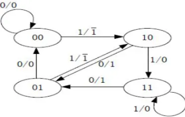
The state diagram of the Radix-2 Booth multiplier is shown in Fig.1. Here we have four different types of states. For 00, 11 states we can perform multiplication of multiplicand with zero. For 01 state, we can multiply multiplicand with one whereas for 10 state, we can multiply multiplicand with -1.
Fig. 1 State Diagram for Radix-2 Multiplier
ASM chart
The Fig.2 shows the ASM chart for Radix-2 booth multiplier. It represents conventional procedure for various operations required with respect to state of machine. Here we generate the partial products by Radix-2 booth encoder. By using this technique we can reduce the partial products generation and the computation time delay is less than ordinary multiplication.
Qn Qn+1 Recorded Bits Operations Performed
0 0 0 Shift
0 1 +1 Add M
1 0 -1 Subtract M
Fig. 2 ASM chart for Radix-2 Booth Multiplier To generate recoded multiplier for radix-2, following steps are to be performed. i) Append the given multiplier with a zero to the LSB side.
ii) Make group of two bits in the overlapped way Recode the number using the above table. Consider an example which has the 8 bit multiplicand as 11011001 and multiplier as 011100010.
Multiplicand 1 1 0 1 1 0 0 1
Multiplier 0 1 1 1 0 0 0 10
↓ ↓ ↓ ↓ ↓ ↓ ↓ ↓
Recoded multiplier +1 0 0 -10 0+1-1
0 0 0 1 0 0 1 1 1
1 1 1 0 1 1 0 0 1
0 0 0 0 0 0 0 0 0
0 0 0 0 0 0 0 0 0
0 0 0 1 0 0 1 1 1
0 0 0 0 0 0 0 0 0
0 0 0 0 0 0 0 0 0
1 1 1 0 1 1 0 0 1____________
Product 0000001001001001___
The peak power of a circuit can be defined as
max=∫Vdd.idd(t)dt (1)
Where Vdd is the supply voltage and idd (t) is the amount of current drawn by the circuit at time.
Given this equation, minimization of the peak power at a given time is directly proportional to the amount of current drawn at time. Since current is flowing ideally only when a circuit is active, by minimizing the number of simultaneously active elements, we can reduce the spike in currentdrawn from the power supply, thus reducing the IR-voltage drop.
In this proposed work to realize high speed multipliers is to enhance parallelism which helps to decrease the number of subsequent calculation stages. The original version of the Booth algorithm (Radix-2) had two drawbacks.
They are: 1) The number of add subtract operations and the number of shift operations becomes variable and becomes inconvenient in designing parallel multipliers.(ii)The algorithm becomes inefficient when there are isolated 1’s. These problems are overcome by using modified Radix 4.Booth algorithm which scans strings of three bits is given below: 1) Extend the sign bit 1 position if necessary to ensure that n is even.2) Append a 0 to the right of the LSB of the multiplier.3) According to the value of each vector, each Partial Product will be 0, +M,-M, +2M or -2M.
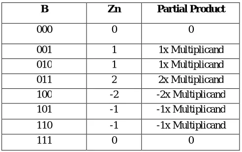
The negative values of B are made by taking the 2’s complement and in this paper Carry-look-ahead (CLA) fast adders are used. The multiplication of M is done by shifting M by one bit to the left. Thus, in any case, in designing n-bit parallel multiplier, only n/2 partial products are produced. The partial products are calculated according to the following rule
Zn= -2×Bn+1 + Bn +Bn-1 --- (2)
Where B is the multiplier.
Table 2. Modified Radix-4 Recoding Rules
B Zn Partial Product
000 0 0
001 1 1x Multiplicand
010 1 1x Multiplicand
011 2 2x Multiplicand
100 -2 -2x Multiplicand
101 -1 -1x Multiplicand
110 -1 -1x Multiplicand
111 0 0
B. Booth Multiplication Algorithm for Radix-4
One of the solutions of realizing high speed multipliers is to enhance parallelism which helps to decrease the number of subsequent calculation stages. The original version of the Booth algorithm (Radix-2) had two drawbacks. They are:
(i) the number of add subtract operations and the number of shift operations become variable and become inconvenient in designing parallel multipliers. (ii) The algorithm becomes inefficient when there are isolated 1’s. These problems are overcome by using modified Radix-4 Booth multiplication algorithm. The design approach of Radix-4 algorithm is described with the pictorial views of state diagram and ASM chart. This algorithm scans strings of three bits as follows:
1) Extend the sign bit 1 position if necessary to ensure that n is even. 2) Append a 0 to the right of the LSB of the multiplier.
3) According to the value of each vector, each Partial
multiplicand with 0,-1 and -2 consecutively. The pictorial view of the state diagram presents various logics to perform the Radix-4 Booth multiplication in different states as per the adopting encoding technique.
State diagram
Fig.3. State diagram of Radix-4 Booth Multiplier
ASM chart
The ASM chart for Radix-4 booth multiplier is as shown inFig.4. This represents the conventional flow of operations that are required for Radix-4 booth multiplier in various states. Here we can generate the partial products by Radix-4 booth encoder. By using this technique we can further reduce the partial products generation and the computation time delay, which is less than that of Radix-2 multiplication.
Fig. 4 ASM chart for Radix-4 Booth Multiplier Consider example for radix 4:
Multiplicand 1 0 0 0 0 0 0 1
↓ ↓ ↓ ↓
+2 0 0 -2
0000000011111110
00000000000000
000000000000
1100000010
Product 1100000101111110
V. RESULTS
We evaluate the performance of Radix-2 and Radix-4 booth multipliers and implement them on FPGA. For Design Entry, we used ModelSim 6.3f and design with VHDL. In order to get the power report and delay report we synthesize these multipliers using Xilinx ISE 9.1i. The comparison of synthesis report for Radix-2 and Radix-4 Booth multipliers is given in Table 3.
VI. CONCLUSION
In this paper, the Radix-2 and Radix-4 booth multipliers are designed using VHDL. The delay and power dissipation of modified radix-4 Booth multiplier is less as compared to the Radix-2 booth multiplier. When implemented on FPGA, it is found that the radix-4 booth multiplier consumes less power than radix-2 booth multiplier. Also estimated delay is less for radix-4 booth multiplier.
REFERENCES
[2] Shiann-RongKuang, Jiun-Ping Wang, and Cang-Yuan Guo, “Modified Booth multipliers with a Regular Partial Product Array,” IEEE Transactions on circuits and systems-II, vol 56, No 5, May 2009.
[3] Li-Rong Wang, Shyh-JyeJou and Chung-Len Lee, “A well-tructured Modified Booth Multiplier Design” 978-1-4244-1617-2/08/$25.00 ©2008 IEEE.
[4] Soojin Kim and Kyeongsoon Cho “Design of High-speed Modified Booth Multipliers Operating at GHz Ranges” World Academy of Science, Engineering and Technology 61 2010.
[5] Shiann-RongKuang, Member, IEEE, Jiun-Ping Wang, and Cang-Yuan Guo” Modified Booth Multipliers With a Regular Partial Product Array” IEEE TRANSACTIONS ON CIRCUITS AND SYSTEMS—II: EXPRESS BRIEFS, VOL. 56, NO. 5, MAY 2009 1549-7747
[6] Ravindra P Rajput and M. N ShanmukhaSwamy” High speed Modified Booth Encoder multiplier for signed and unsigned numbers” , 2012 14th International Conference on Modelling and Simulation 978-0-7695-4682-7/12 © 2012 IEEE.
[7] A. P. Chandrakasan and R. W. Brodersen, Low-Power CMOS Design. Piscataway, NJ: IEEE Press, 1998.
[8]A. D. Booth, “A Signed Binary Multiplication Technique,” Quarterly J. Mechanical Applications in Math., vol. 4, part 2, pp.236-240,1951. [9] John G.Proakis, Dimitris G. Monolakis, “Digital Signal Processing,Principles,Algorithms, and Applications”, Fourth Edition.
[10] A. Dandapat, S. Ghosal, P. Sarkar, D. Mukhopadhyay (2009), “A 1.2-ns16×16-Bit Binary Multiplier Using. High Speed Compressors”, International Journal of Electrical, Computer, and Systems Engineering, 2009, 234-239.
[11] J. Gu, C.H.Chang (2003), “Ultra low voltage low power 4-2 compressor for high speed multiplications”. Circuits and Systems,2003.ISCAS ’03. Proceedings of the International Symposium, vol. 5, May 2003, 321-324.
[12] Israel Koren, Computer arithmatics algorithms A.K.Peters Ltd. ISBN 1568811608.