Synchronous Reference Frame Based Hybrid Shunt Filter
for Current Harmonic Compensation
R. Rambabu & K. Kranthi Pratap Singh
P.G Scholar, Department of EEE, ASR College of Engineering &Technology, JNTUK, A.P
Assistant Professor, Department of EEE, ASR College of Engineering &Technology, JNTUK, A.P
ABSTRACT:
A power quality problem is an occurrence manifested as nonstandard voltage, current or frequency that results in failure or faulty operation of end use equipment. Presence of harmonics in supply voltages and currents is a serious issue that results in increased power loss in utility power systems and failure of sensitive, electronic loads. Active filters are special equipment that uses power electronic converters for compensation of current and/or voltage harmonics originated by non-linear loads, or to avoid those harmonic voltages that might be effect operation of sensitive loads. This project mainly emphasizes on the application of simulation tool for analysis of the effectiveness of shunt active power filter in harmonics currents suppression in real time power system. A model of a three-phase three-wire shunt active power filter based on synchronous reference frame control strategy has been designed and simulated on MATLAB/SIMULINK. Simulation results indicate that the proposed active power filter can restrain harmonics of electrical source current effectively and also demonstrates the usability of simulation.
Keywords: Non Linear Load; Hybrid; Filter;
Compensation; Control
1. INTRODUCTION
The extensive application of non linear loads in domestic, commercial, industrial sector causes power quality problems such as harmonic current,
poor power factor, unbalance, voltage sag and swell, reactive power burden etc. Some of the examples of nonlinear loads are uncontrolled and controlled rectifiers; variable speed drives both Alternating Current and Direct Current, uninterrupted power supplies etc. These nonlinear loads may cause poor
power factor and high degree of harmonics. Active power filter technology is the most efficient way to compensate for reactive power and cancel lower This paper emphasizes on elimination of current harmonics and reactive power compensation; hence shunt APF topology has been considered
2. HYBRID ACTIVE POWER FILTER The hybrid active power filter is nothing but the series combination of active power filter and the passive elements. The harmonics in the power system can be removed in the following ways.
By providing a low impedance path to ground for
harmonic signal.
By injecting compensating signals which are in
phase opposition with the harmonic signal present in the system.
For the first one we can use passive tuned filter and for the latter active filter can be used.
Active filter is connected in series with the passive filter through a coupling transformer.
3. SHUNT ACTIVE POWER FILTER
4. CIRCUIT CONFIGURATION
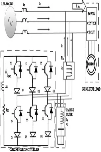
Fig.1 shows a proposed system consisting of a Shunt active power filter and Passive filter. The purpose of using this combined system is to reduce the
harmonics effectively. The power-factor also
improved by using the combined system.
Figure 1: Circuit configuration of hybrid filter The main circuit of the active filter is the VSI with PWM modulation using IGBT switches The current source hybrid power filter is a combination of current source active power filter and passive LC filter. APF is an inverter circuit capable of producing the bidirectional compensating current components. A passive power filter consists of an inductor and a capacitor tuned for a fifth order harmonic frequency and seventh harmonic frequency. Current source realized with the inductor, is feeding a power converter which is considered as the harmonic source. The diodes in APF enable the device to withstand direct and reverse voltages produced by the DC link inductor .The inverter is connected in parallel with the load at PCC using coupling inductor. The power devices of the CSAPF are rated for the maximum possible voltage and current.
The passive power filter (PPF) is connected in parallel with CSAPF is tuned to mitigate the fifth order harmonic current thereby reducing the power
requirement of APF. The value of PPF components are calculated with the harmonic frequency which has to be eliminated. The L and C are determined by using the Eq. (1). The value of the L and C for the given frequency is determined with large value for C and small L for minimizing the ripples. For compensation of nth harmonic current, passive filter inductance, L and capacitance, CF are determined by the equation,
„n‟ is harmonic order and „ω‟ is the fundamental frequency.
5. SYNCHRONOUS REFERENCE FRAME METHOD
The performance of an active power filter depends Mainly on the selected reference generation scheme.The current reference template must include the amplitude and phase information to produce the desired current component compensation, while keeping the voltage across the dc bus constant The reference generation scheme must operate adequately under steady state and transient condition.The algorithm taken into consideration. Here for extracting reference currents is the Synchronous Reference Frame Method.
5.1 Principle of SRF Method
The line frequency components of the load currents become DC quantities and the harmonic components are frequency shifted by ωs in the d-q reference frame. A high pass filter in the d-q frame, with a cutoff at the line frequency can be used to extract the DC components. If the phase of the d-axis current is locked to the phase voltage, ea, of the a-b-c coordinates with a phase locked loop (PLL), and then the Id component represents the fundamental real current and Iq represents the fundamental reactive component. By subtracting these quantities from Id and Iq, the harmonic content is obtained as shown in (4) and (5)
These quantities can then be used to develop the compensating quantities for the active filter by transforming back to α-β coordinates and then to a-b-c a-b-coordinates using (6) and an inverse transformation (7)
currents would be separated simultaneously to DC and AC parts. AC part of d axis and whole current in q axis are used for harmonics elimination and VAR compensation. Zero current is produced due to a
three-phase voltage imbalance or waveform
distortions which have not been considered in this paper. Finally, compensatory currents are determined by adverse Park transformation on d and q axis to be injected to the network after tracing and reconstruction.
6. SIMULATION RESULTS
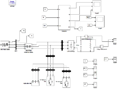
The model for a three phase three wire shunt active power filter using SRF method has been successfully
modeled and tested using MATLAB/SIMULINK toolbox. The performance of APF in steady state condition is evaluated using FFT simulation.
Figure 2: Simulation model of shunt HPF
Figure 3: Simulation model of shunt APF
Figure 5: voltage and current across load with shunt HPF
Figure 6: waveform of current injected from shunt APF
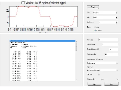
Figure 7: THD of nonlinear load without filter using FFT Analysis tool
Figure 8: THD of nonlinear load with shunt HPF using FFT Analysis tool
7. CONCLUSION
From the results it is observed that SRF theory based active hybrid filter can be used for elimination of harmonics for a three phase three wire system supplying a nonlinear load. A model of a three-phase three-wire shunt active power filter based on synchronous reference frame control strategy has
been designed and simulated on
MATLAB/SIMULINK. Simulation results indicate that the proposed active power filter can restrain harmonics of electrical source current effectively and also demonstrates the usability of simulation.THD reduced from 26.64% to 2.74% using hybrid shunt Active power filter.
8. REFERENCES
[1] S. Rahmani, K. Al-Haddad and F. Fnaiech, "A threephase shunt active power filter for damping of harmonic propagation in power distribution networks", Proc. IEEE International symposium on Industrial Electronics, vol. 3, pp. 1760-1764, July 2006
[3] H. Akagi “Trends in active power line conditioners” IEEE Transactions on Power Electronics, Vol. 9, No. 3, May 1994. Pp. 263-268
[4] E.Latha Mercy, R.Karthick, S.Arumugam,
“A comparative performance analysis of four control algorithms for a three phase shunt active power filter”, IJCSNS International Journal of Computer Science and Network Security, VOL.10 No.6, June 2010
[5] Moleykutty George and Karthik Prasad Basu, “Performance Comparison of Three-Phase Shunt Active Power Filter Algorithms”, American Journal of Applied Sciences, Vol.5,No.11,pp. 1424-1428, 2008
[6] Naimish Zaveri, Ajitsinh Chudasama,
“Analysis of Different Real Time Reference
Generation Techniques used for Harmonic
Mitigation in Three Phase Shunt Active filters”, International Journal of Recent Trends in Engineering, Vol 2, No. 7, November 2009
[7] B.S. Rajpurohit, S.N. Singh “Performance Evaluation of Current Control Algorithms Used for Active Power Filters”, Proc. EUROCON, 2007. The International Conference on “Computer as a Tool”; 9-12 Sept. 2007,pp. 2570 – 2575
[8] Donghua Chen, Shaojun Xie, “Review of the
control strategies applied to active power filters”, Proc. 2004 IEEE International Conference on Electric Utility Deregulation, Restructuring and Power Technologies, Vol.2, April 2004 pp 666 – 670
[9] G.W.Chang and T.C.Shee, “A comparative study of active power filter reference compensation approaches”, Proc. IEEE Power Eng. Soc. Summer Meeting, Vol.2,July 2002, pp. 1017-1021.
[10] Bhattacharya, M. Divan, and B. Benejee, “Synchronous Reference Frame Harmonic Isolator Using Series Active Filter”, 4th European Power