A Comparative Study Based on PI and Fuzzy Control of
Inverter fed Induction Motor Drive
Sourabh Mehto1; Rahul Agarwal2; Manish Shah3
1 MTech ScholarDepartment of Electrical & Electronics, VITS Indore (M.P.) India,
2 Asst Prof Department of Electrical & Electronics, VITS Indore (M.P.) India,
3Asst ProfDepartment of Electrical & Electronics, VITS Indore (M.P.) India,
Email: [email protected]; [email protected]; [email protected]
Abstract
Induction motor drive draws heavy current during starting condition. The current is 4 to 7 times of rated current, if this current present in the motor for large time period not only it can damage insulation but conductors too. If this transient period for achieving rated speed is large it can causes above problems. The equipment which reduces the transient time of induction motor is controlled operation of Voltage Source Inverter but using this one; introduces harmonics in the machine and in system. These harmonics can cause overheating of the motor and supply system result in reduction in overall life span of motor, reduced efficiency, poor performance and unwanted failure of drive system causes economic Burdon on organization in form of less production. To solve these issues an attempt is made to make a comparative study on various open loop and close loop drive including PI controller & Fuzzy Logic controller for determination of their advantages and limitations for any particular operation of drive.
Keywords:
Simulink; THD; PI; Fuzzy controller
Introduction
An inverter is used at many levels for variable voltage & frequency outputs. The domestic and low voltage commercial
its moving elements.) of the machine and its impact on applied loads. It also provides self starting of the motor. Due to power electronics commutation the motor is protected and the controller is also protected from, Damages.
I. Open loop Inverter
The open loop control strategy is the simplest way to control the different parameters of a drive system. In this method the inverter input is not directly connected and bounded with output. The technique is initially set as per the desired output if output changes there will be requirement of some external measurement for change in input supply. Fig shows the three phase inverter circuit using 180 deg mode of conduction. This simulation is performed on Simulink. IGBT is used as switching device for the inverter. Pulse generator is used for gating signal for switching device. Then DC is converted in to AC which is fed to three phase resistive load. Then scope is used to measure all the voltage and current.
Fig2.1: Open loop Inverter
II. Close Loop Control using PI Controller
After getting results from open loop control, a close loop control of induction motor is applied. In this control method a PI controller is used to provide a control signal according to error from the output. Fig 3.1 shows the close loop control of induction motor using PI controller.
Fig3.1: Close Loop Control using PI Controller
III. Close Loop Control using Fuzzy
Logic Controller
After getting non satisfactory result from the PI controller, a fuzzy controller is applied in close loop control of induction motor. This fuzzy controller improve the result of induction motor. And also improve the THD of induction motor. The simulink model of fuzzy controller applied on close loop control of induction motor shown in fig 4.1
Fig4.1: Close Loop Control using FuzzyController
IV. RESULT
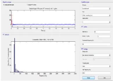
Simulation Result of Open loop inverter
Fig 5.1: THD Analysis of Rotor Current
The below result shows the THD analysis of stator current when fundamental freqency is applied. Fig shows the THD of stator current.
Fig 5.2: THD Analysis of Stator Current
Simulation Result of Closed loop using PI controller
After the calculation of normal speed, torque and current it is important to know the harmonics distortion of model.
THD analysis of rotor current
Fig 5.3: THD Analysis of Rotor Current
THD analysis of stator current of induction motor is shown in fig 6.4
Fig 5.4: THD Analysis of stator Current
Simulation Result of Closed loop using fuzzy controller
After the calculation of normal speed, torque and current it is important to know the harmonics distortion of model. THD Analysis of Rotor Current
Fig 5.5: THD Analysis of Rotor Current
Fig 5.6: THD Analysis of Stator Current
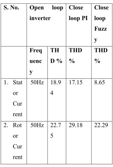
Table 1:
Comparison results of THD in Open loop, Close loop PI and Close loop Fuzzy
Controller
V. Conclusion
The result obtained through simulation shows that close loop controller for IM drive system has superior over conventional and open loop controller.
Even in close loop control; Soft controller are preferable. These controllers have vast range of applications in industrial and commercial segments and domestic uses too like Washing machines. VFD has been using vastly in all segments. These drives may get more efficiency and better performance using soft techniques like ANN & GA.
References
[1] Mohan undeland, Riobbins “Power Electronics converters, Application and design” john wiley and sons 2012. [2] Cyril W. Lander “Power Electronics”
Mc Graw Hill 1993.
[3] V.R.Moorthi “Power Electronic devices circuits and Industrial application” Oxford University 2010. [4] M.S. Jamil Asgar “Power Electronics”
Phi Learning 2009.
[5] Joseph Vithayathil “Power Electronics principle and application” TATA Mc Graw Hill 2010.
[6] M. H. Rashid, “Power electronics circuits, devices and applications” Prentice-Hall, Inc., july2000.
[7] G. K. Dubey, “Power semiconductor controlled drives” Prentice Hall, New Jersey, 1989.
[8] Shailendra Jain, “Modeling & Simulation Using Matlab-Simulink” Wiley India, 2012.
[9] Biswamoy pal, Aniruddha Mukherjee “Comparative performance Analysis and THD Calculation of Carrier Signal Based IGBT and MOSFET Single Phase Inverter” IOSR Journal of Electrical and Electronics Engineering (IOSR-JEE) e-ISSN: 2278-1676, p-ISSN: 2320-3331, Volume 9, Issue 2 Ver.I Mar-Apr.2014,
[10] Debaprasad Kastha,Asim Kumar Majumdar “An Improved Starting For Voltage-Source Inverter Fed Three Phase Induction Motor Drives Under Inverter Fault Conditions”IEEE
Transactions on power
Electronics.Vol.15,No.4,July2000. [11] Zheng chen,Yiying Yao,Dushan
Boroyevice,Khaid T.Ngo,Kanshik
S. No. Open loop
inverter
Close loop PI
Close loop Fuzz y Freq
uenc y
TH D %
THD %
THD %
1. Stat or Cur rent
50Hz 18.9 4
17.15 8.65
2. Rot or Cur rent
50Hz 22.7 5
Rajashekara “A 1200- V,60-A,Sic Mosfet Multichip Phase-Leg Module For High-Temperature,High Freguency,Application”IEEE
Vol.29,No.5,May 2014.
[12] S. Castagno,R D Curry, and E. Loree, “Analysis and comparison of a fast turn on series IGBT stack and high voltage rated commercial IGBTS” IEEE Trans. Plasma Science,vol. 34 pp.1692-1696, October 2006.
[13] Nitin Goel,P.R.Sharma,Suman Bala “Performance Analysis of SPWM Inverter Fed 3-Phase Induction Motor Drive Using MATLA/Simulink” international journal of advance technology in Engineering and science,vol.02,june2014.
Authors Biography:
Sourabh Mehto-
Pursuing M.Tech in Power Electronics form Vindhya Institute of Technology and science Indore, MP (INDIA). He completed B.E in 2011 from VITS Indore. His field of interest for research is Power Electronic, Electric Machine, Electric Drives, MATLAB, PSIM and Arduino.
Rahul Agrawal -was born in Hoshangabad, (MP), India in 1978. He received the B.E. degree in Electrical Engineering from JIT Khargone, India in 2001, and M.E. in Power Electronics from SGSITS Indore, India in 2008. Presently, he is an Assistant Professor with the Department of Electrical Engineering, Vindhya Institute of Technology & Science Indore, and pursuing a Ph.D. at Maulana Azad National Institute of Technology Bhopal, India. He has 11 years
of teaching experience. He has many research publications in various International and national conferences. His current research interests are in the areas of power electronics, HVDC and FACTS. He is a student member of IEEE and life member of ISTE, India.