Experimental analysis of Waste heat recovery using TEG for
an internal combustion Engine
Dr. N. K. SaikhedkarP 2
P
, Anchal DewanganP 1 Department of Mechanical Engineering
M.Tech Scholar P
1
P
,ProfessorP
2
P
, RIT Raipur.
ABSTRACT
With the rapid development of population and
vehicle industry in the world during the past
20th century, the demand on passenger vehicles
has increased sharply. Only 41% of a diesel
engine’s fuel combustion energy is converted
into useful work to drive a vehicle and its
accessory loads. The remainder is waste heat
dissipated by engine exhaust system and also the
convection as well as radiation heat loss from
engine block. This increases fuel consumption
which brings serious energy crisis and has
environmental effects. As 30% to 40% of
exhaust gases containing heat energy liberated
from the internal combustion engine, and having
temperature up to 200P
o
P
C to 250P
o
P
C are wasted
directly to the atmosphere. So the objective of
the work is to utilize that heat energy of internal
combustion engine. By utilizing that heat energy
of fuel which is consumed in the internal
combustion engine can be reduced which
increases efficiency of internal combustion
engine. The work is to design a duct that can be
modified in order to increase the heat transfer so
that maximum heat can be dissipated to hot side
of TEG module. Further fins can be used in the
design of the duct, which will increase heat
transfer also.
Keywords: TEG module, Seebeck coefficient
effect, ICE, N-P type element Thermocouple.
1. INTRODUCTION
Recent studies indicate that, if this waste heat of
IC engines could be recaptured efficiently,
engine output power will be significantly
enhanced without additional fuel consumption.
Thus, large amount of fossil fuel can be saved
and much less harmful exhaust gases are
dissipated to environment when the same output
power is generated. Furthermore, global
warming will be relieved. However, it should be
noticed that the potential energy savings from
improved energy efficiency are estimated using
basic physics principles and engineering models.
The actual energy savings from such
improvements generally falls short of such
estimates due to the rebound effect. A possible
explanation for this phenomenon could be that
such improvements encourage the consumption
of energy services where part or all of the gain
would be offset by the increase in consumption.
Since the price of fossil fuel rises greatly due to
serious energy crisis, renewable clean energy
will play an important role in the future. In other
words, it is a considerable solution to improve
engine efficiency via waste heat recovery
system. In particular, it has considerable
potential environmental and economic benefits.
New opportunities for efficiently recovering
waste heat have been created because of
advances in micro- and nano-technologies. The
key to identifying TEG waste heat recovery
applications is to determine when thermal
exchange between existing process fluids is not
an available option or provides no useful
technical or economic benefit. The quality of
waste heat (i.e., temperature, composition,
energy content, and accessibility) varies
significantly and depends on the industrial
process emanating it.
Thus, many researches and projects focus on
enhancing engine performance and thermal
efficiency, aiming at lowering fuel requirement
and exhaust that are harmful to human body.
Converting exhaust heat to electricity by
“Thermoelectric generator module” is an
interesting and actual avenue among many
methods of recovering the waste heat.
2. INTRODUCTION TO TEG &
THERMOELECTRIC THEORY
Thermoelectric generator modules are solid
device which can convert heat or temperature
difference into electrical energy. Thermoelectric
elements are made of P type and N type
semiconductor. Thermoelectric modules are
based on Seebeck effect. When there is a
temperature difference between two sides of
semi conductor, a voltage is created. Current
flows from N type element and passes into P
type element. Thermoelectric modules are
devices that either convert thermal energy from
a temperature gradient into electric energy or
vice versa, convert applied electric energy into a
temperature gradient. [1]
2.1 Thermoelectric Power Generation: The
thermoelectric power generation is based
on the Seebeck effect – If heat is applied to
a circuit at the junction of two different
conductors, a current will be generated.
Seebeck tested a wide range of materials,
including the naturally found
semiconductors ZnSb and PbS. [2] The
Seebeck coefficient measured in micro
volts/K is defined as the open circuit
voltage produced between two points on a
conductor when a uniform temperature
difference of 1 K is applied between those
points.
2.2 Thermoelectric Heating and Cooling:
Thermoelectric heating and cooling devices
are based on the Peltier effect – If a current
ispassed through a circuit of two dissimilar
conductors, there will be a rise or fall in
temperature at the junction depending on
the direction of the current flow. When
electric input is applied to a thermocouple,
as shown in figure 4. Electrons move from
p- type material to n-type material
absorbing thermal energy at the cold
junction. The electrons dump their extra
energy at the hot junction as they flow from
n-type back to the p-type material through
the electrical connector. Removing heat
from the hot side will drop the temperature
on the cold side rapidly.
2.3
Material used for TEG
Among the vast number of materials known
to date, only a relatively few are identified
as thermoelectric materials. Thermoelectric
materials can be categorized into
established (conventional) and new (novel)
materials. Today's most thermoelectric
materials, such as Bismuth Telluride
(Bi2Te3)-based alloys and Pb-Te-based
alloys, have a ZT value of around unity (at
room temperature). However, at a ZT of 2-3
range, thermoelectric power generators
would become competitive with other
power generation systems. Effective
thermoelectric materials should have a low
thermal conductivity but a high electrical
conductivity. A large amount of research in
thermoelectric materials has focused on
increasing the Seebeck coefficient and
reducing the thermal conductivity,
especially by manipulating the
nanostructure of the thermoelectric
materials. Different thermoelectric material
can be used depending upon temperature
difference which we are getting between
hot side and cold side of the TEG module.
Material with range of temperature for
which TEG is made is given in the table
below.
Table-1.1: Material used in TEG with range of temperatures
Sno TEG Material Temperature
Range
1 Alloys based on Bismuth (Bi) in combinations with Antimony(An), Tellurium (Te) or Selenium (Se)
Low temperature up to 450K 2 Materials based on alloys
of Lead (Pb)
Intermediate temperature up to 850K 3 Material based on Si-Ge
alloys
Higher temperature upto1300K
Although the above mentioned materials still
remain the corner stone for commercial and
practical application in thermoelectric power
generation, significant advances have been made
in synthesizing new materials and fabricating
material structures with improve thermoelectric
performance and by reducing the thermal
conductivity [2].
3.
Related Work
The waste gases are obtained from different
sources like automobile, industries, heat
generated from solid waste etc. The main aim is
to convert these heats into useful energy. To do
these we require a system by which it is possible
to convert heat into useful work. The properties
of material also play main role while selecting
the TEG for calculation of energy and exergy of
exhaust gases. G. shu, J. Zhao, H. Tian, X.
Liang, H. Wei [1]-The paper analyzes the
combined TEG-ORC (thermoelectric generator
and organic Rankine cycle) used in exhaust heat
recovery of ICE. They calculated the optimal
parameters of the bottoming cycle based on
thermodynamic theory when net output power
and volumetric expansion ratio are selected as
objective functions, which affect system
performance and size. The effects of relative
TEG flow direction, TEG scale, highest
temperature, condensation temperature,
evaporator pressure and efficiency of IHE
(internal heat exchanger) on system
performance. R123 is chosen among the fluids
whose decomposition temperature exceeds 600
K to avoid fluid resolving and resulting in wet
stroke when expansion process ends.B. I. Ismail,
W. H. Ahmed. [2] Worked on use of
thermoelectric module, performance parameter.
“Figure of merit” which plays an important role
in behavior of thermoelectric generator module.
Efficiency of thermoelectric modules basically
depends on “Figure of merit” Z and operating
temperature difference. This paper mainly pays
attention toward the applications of this
conversion system in wide area like micro-scale
waste heat application as in electronic chip in
domestic gas-monitoring system etc.
M. He, X. Zhang, K. Zeng, K. Gao, worked on
waste heat of combined cycle (i) Organic
rankine cycle, for recovering waste heat of oil
lubricant (ii) Internal combustion engine, for
recovering waste heat of high temperature
exhaust gases. For studying the energy balance
of ICE an experiment was conducted on a
TOYOTA 8A gasoline engine. In their work
energy and exergy analysis of waste heat from
exhaust gases is done [5]. X. Gao, S. Juhl,
Andreasen, M. Chen, S. Knudsen Koer. They
presented a numerical model of an exhaust heat
recovery system for a high temperature polymer
electrolyte membrane fuel cell (HTPEMFC)
stack. They designed a system in which
thermoelectric generators are sandwiched in the
walls of a compact plate fin heat exchanger.
Their model is based on finite element approach.
In this approach they calculated fluid properties,
heat transfer process and TEG performance.[6]
M. strasser, R. Aigner, M. Franosch, G.
Wachutk worked on miniaturized thermoelectric
generators, which are being developed to
convert waste heat into a few microwatt of
electrical energy. In order to optimize the
device, they suggested that material should have
low thermal conductivity which increases output
power. Materials which they have used are
poly-Si and poly-si-Ge. [8]
4. EXPERIMENTAL SETUP FOR WASTE
HEAT RECOVERY
A description of experimental setup is explained
including description of ICE, rectangular duct,
connection of thermoelectric generator and
devices for measuring different temperatures and
voltages etc. The test rig is made which consists
of a vertical single cylinder water cooled
compression ignition type diesel engine. It is
coupled to a loading dynamometer;
all the components are mounted on heavy duty
MSchannel.
A desk type control panel consists of following
instrumentations. A Digital RPM indicator to
measure speed of the engine. A Digital
temperature indicator to measure various
temperatures and a Burette with manifold to
measure the rate of fuel consumption during test.
4.1
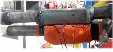
Description of Rectangular ductA duct made up of stainless steel is used in the
experimental setup to flow hot exhaust gases
which is exhausted from the exhaust manifold of
the internal combustion engine. A device known
as thermoelectric generator is placed at the top
of the duct. It is a solid device which converts
heat taken into electricity directly. In setup two
TEG modules are used and they are connected in
series. When they are connected in series
performance increases. To ensure that maximum
heat flow toward top of duct, insulation is
required, that is a combination of insulation
paper and cotton, so that maximum heat can be
utilized by TEG modules. The specification of
duct considered is Rectangular shape with Size
of 13 cm× 4 cm× 3 cm and Material used is
Stainless steel. Figure below shows combination
of both duct with TEG sandwiched in between.
To measure the voltage generated between two
terminals of TEG, multi-meter is used. And for
measuring temperature at the hot side and cold
side of the duct a thermocouple is used. During
measurement of temperature one point of the
thermocouple is set to zero value hence
difference in temperature itself gives value of
temperature of hot and cold side respectively.
Figure below shows the image of multi-meter
and thermocouple which is used to measure
voltage and temperature respectively
4.2
Working procedure of the setupIn this experimental setup, experiment is done
for finding the different parameters like “mass of
fuel consumed, amount of heat added, brake
power obtained from rope brake dynamometer,
amount of heat carried by exhaust gases” at
different load and speed of the engine. Test is
performed for three different speeds and ten
different loading conditions. The procedure for
finding the above parameters are described
below:
(i) Fill up the diesel into the fuel tank
mounted on the panel frame.
(ii) Check the lubricating oil in the oil sump
(iii) Connect the instrumentation power
input plug to a 230 volt, single phase
power source. Now a digital meter RPM
and temperature indicators display the
respective readings.
To conduct the performance test on the engine
(i) Open the fuel valve and ensure no air
trapped in the fuel line
(ii) Start the engine and allow it to settle at
rated speed. At first speed of the engine
is set to the 1300 RPM. Apply the load
by rotating the hand wheel on the
dynamometer gradually to the desired
load. Load for constant speed varies
from 2 kg to 20kg.
(iii) Mass of fuel consumed in the burette in
cc is measured at speed of 1300 RPM
and by varying load from 2 kg to 20 kg
respectively
(iv) Different temperatures like temperature
of hot exhaust gases, temperature of hot
exhaust gases , temperature of water
inlet and outlet to & fro from is
measured by the indicator.
(v) Repeat the same procedure for speed of
1400 RPM and 1500 RPM as above.
Now test is performed for calculation of power
obtained from TEG modules, which are
connected in series at the top of duct. The
procedures for finding are as follows:
(i) Connect the duct to the exhaust
manifold of the internal combustion
engine.
(ii) There should be proper connection of
the duct to the exhaust manifold so that
there should not be any leakages at the
junction of the exhaust manifold and the
duct pipe.
(iii) Connect the two terminals of the TEG
modules with multimeter and place the
thermocouple rod at the top of duct at
different load and speed conduction.
(iv) Start the engine and set speed & load of
the engine to a desired value. Here at
starting calculation is made for 1300
RPM with load from 2 kg to 20 kg
(v) Note down the temperature at the top of
duct and voltage generated at each and
every set of speed.
(vi) At first the reading was taken by the
cold side of TEG when opened to
atmosphere and then the cold fluid is
made to flow in the upper duct which is
kept at the top of the TEG.
(vii) Repeat the same procedure for speed of
1400 RPM, 1500 RPM with different
loads.
5 METHODOLOGY
5.1
Energy analysis of fuel in ICE
The amount of heat given to the heat engine is
ENERGY and maximum useful work which we
can obtain by converting this heat into work is
known as available energy or EXERGY of the
system. Some amount of heat which goes on
waste is known as unavailable energy. The
whole process of heat engine is shown in figure
below:-
For calculating the brake power, mass of fuel
consumed and amount of heat contained in
exhaust gases can be calculated by following
relationship.
5.1.1Calculation of brake power of engine
𝐵𝑃 = 𝑇 × 𝜔
Where 𝜔 is angular velocity (in rad/sec) of
engine, which can be calculated by
𝜔 = 2𝜋𝑁/60
N is speed in revolution per minute (RPM)
T Torque generated which can be calculated as
T = spring balance difference × g × effective
brake drum radius
P = brake power produced. Brake power (BP)
produced (in kJ/s) can be find out by
5.1.2 Calculation of mass of fuel consumed and
heat added to engine
Mass of fuel consumed (in kg/hr) in the
combustion chamber can be calculated by:- 𝑚𝑓𝑐 = (𝑋 × `10^ − 6 × 820)/(300)
Where X is burette reading in cc, 820 is density
of diesel in Kg/mP
3
P
, t is time taken in sec.
If mass of fuel consumed is known, by
conidering calorific value of fuel (𝐶RfR), amount of
heat added to engine can be calculated by
Amount of heat added 𝑄RaR= 𝑚𝑓𝑐 × 𝐶Rf
5.1.3 Calculation of amount of heat contained in
exhaust gases
Heat carried away by exhaust gases (Qeg) can
be worked out by applying “First law of
thermodynamics”. While calculating the heat
carried by exhaust gases it is assumed that no
heat is transferred to atmosphere and taking that
heat of exhaust gases is completely used for
cooling of engine by flow of water. So from
heat balance:- Heat gained by exhaust gases =
heat carried by the cold water that is
(
gi go)
w pw(
wo wi)
peg
eg C T T m C T T
m × × − = × × −
Where meg = mass flow of exhaust gases (kg/s)
=
peg
C Specific heat of exhaust gases (kJ/kg K)
=
w
m
Water flow rate (in kg/s by 1 litre jar)=
pw
C Specific heat of water (4.187 kJ/kgK)
gi
T
= Exhaust gas inlet temperature (in Po
P
C)
go
T = Exhaust gas outlet temperature (in P
o
P
C)
wi
T
= Water inlet temperature (in Po
P
C)
wo
T
= Water outlet temperature (inPo
P
C)
By using above relationship, heat capacity
(meg×Cpeg) can be calculated and heat carried
by hot exhaust gases (in kJ/sec) is given by
Qeg= meg ×Cpeg ×
(
Tgi −Tgo)
6 RESULT & CONCLUSION
This chapter deals with results obtained while
performing experiment on the test rig for
analysis of waste heat recovery from waste
exhaust gases of ICE. In the experimental setup
test is performed for calculation of mass of fuel
consumed, amount of heat added, brake power
and heat carried away be exhaust gases, heat
transferred to hot side and cold side of TEG and
power obtained from TEG.
At first calculation is made for speed of the
engine of 1300 RPM and load variation of 2 kg
to 20 kg and values like mass of fuel
consumption, amount of heat added to the
engine, amount of heat rejected from the engine
and amount of heat carried away by exhaust
gases is calculated. It was found that maximum
amount of heat carried away by hot exhaust
gases are obtained at speed of 1300 RPM and
load of 20 Kg and the value is 2597.61 J/s.
When TEG is sandwiched between hot junction
and cold junction and speed of engine is
maintained at 1300 RPM with load of 20 kg
and cold water flows at a temperature of 16P
o
P
C,
maximum power obtained from TEG module is
29.94 J/s. Similarly by taking 1400 RPM and
1500 RPM with load variation 2 kg to 20 kg,
maximum amount of heat carried by hot
exhaust gases obtained is 2625.25 J/s for speed
of 1400 RPM with load 20 kg , 7174.84 J/s and
power obtained for 1400 RPM and 1500 RPM
with load 20 kg and water temperature at 16P
o
P
C
are 31.86 J/s and 33.16 J/s respectively.
Graph below is plotted by considering these
parameters with respect to loads and speed.
Finally validation of experimental data is done
by comparing the results obtained by previous
work for different temperature difference and
types of cooling used and it is found that data
obtained by experimental setup is comparable
and reliable.
Sill there is opportunity to search for
semiconductor material which provides high
temperature difference so that maximum heat
can be utilized from system. In future the design
of duct can be modified in order to increase the
heat transfer so that maximum heat can be
dissipated to hot side of TEG module. Further
fins can be used in the design of the duct, which
will increase heat transfer as well.
7 REFERENCES
[1] Gequn Shu, Jian Zhao, Hua Tian, Xingyu
Liang, Haiqiao Wei. Parametric and exergetic
analysis of waste heat recovery system based on
thermoelectric generator and organic rankine
cycle utilizing R123, 28 July 2012
[2] Basel I. Ismail*, Wael H. Ahmed.
Thermoelectric Power Generation Using
Waste-Heat Energy as an Alternative Green
Technology. Revised: November 24, 2008
[3] Mohd Izam Abd Jalil and Jahariah Sampe.
Experimental investigation of thermoelectric
generator modules with different technique of
cooling.; Accepted 2013-03-07
[4] Yuchao Wanga,b, Chuanshan Dai a,b,
Shixue Wang. Theoretical analysis of a
thermoelectric generator using exhaust gas of
vehicles as heat source, 3 January 2013
[5] Maogang He a,*, Xinxin Zhang a, Ke Zeng
b, Ke Gao b. A combined thermodynamic cycle
used for waste heat recovery of internal
combustion engine; Accepted 10 October 2011 0.00 5.00 10.00 15.00 20.00 25.00 30.00 35.00
2 6 10 14 18
Ene rg y in J /se c
Load in Kg
Power obtained from TEG ( in Watt)
Sn. Load Kg Temp. at hot side of duct degree Celsius Temp. at cold side of duct degree Celsius Heat absorbed
by hot side of TEG Qh in Watt Heat received by cold side of TEG Qc in Watt Power obtained from TEG in
Watt
1 2 135 16 371.66 360.79 14.85
2 4 140 16 391.78 378.90 17.28
3 6 146 16 411.28 397.54 18.36
4 8 152 16 427.58 413.59 18.40
5 10 164 16 476.53 457.45 24.56
6 12 172 16 503.42 482.03 26.83
7 14 181 16 531.81 508.09 28.86
8 16 189 16 559.48 532.90 31.65
9 18 197 16 581.93 554.46 32.25
10 20 210 16 619.05 590.44 33.16 Figure 7: Graphical representations of variation of power
obtained from TEG at speed of 1500 RPM and load variation of 2 kg to 20 kg, when cold fluid at 16 degree Celsius is flowing
Table 2: Data obtained from experiment for amount of heat absorbed to hot side of TEG, heat transferred to cold side of
TEG and power obtained from TEG at constant speed of
When cold fluid at 16 degree Celsius is flowing through duct
[6] Xin Gao*, Soren Juhl Andreasen, Min Chen,
Søren Knudsen Kaer. Numerical model of a
thermoelectric generator with compact plate-fin
heat exchanger for high temperature PEM fuel
cell exhaust heat recovery; Accepted 4 -3-2012
[7] R. Saidur a, M. Rezaei a, W.K.Muzammil a,
M.H.Hassan a, S.Paria a,