Study Of Defects By Using Non-Destructive Testing
Through Pulse Echo Method In Ironand Aluminium
Material
1Anjita Srivastava,2Dr. Sanjeev K. Shrivastava,3Dr. Vibhav K. Saraswat 1Research Scholar,2Associate Professor,3Associate Professor
Banasthali Vidyapith, Jaipur
Department of Physics, Bundelkhand University, Jhansi
Department of Physics, ACC Wing, Indian Military Academy, Dehradun
_____________________________________________________________________________________________________ Abstract - Nondestructive testing are being practiced, with beginning fast improvements in instrumentation impelled by innovative advances that happened amid Second World War and the consequent protection exertion. Among the procedures that have been created are color enters, eddy currents. X-rays, ultrasonic and attractive particles. Ultrasonic is especially appealing for non-destructive testing since it very well may be utilized with most sorts of material, and it tends to be utilized to research both their surf experts and their insides.There are six NDT techniques that are utilized frequently. These techniques are visual assessment, penetrant testing, and attractive molecule testing, electromagnetic or swirl current testing, radiography, and ultrasonics testing. These techniques and a couple of others are quickly portrayed underneath.
Keywords - Non-Destructive, Pulse-echoes method, signals detection
_____________________________________________________________________________________________________ 1. INTRODUCTION
It is that branch of physics in that mechanical wave of liquids, gases, and solids such as vibration, infrasound and ultrasonics sound are studied. The persons who work in the acoustics field may be called acoustical engineers. Acoustic word has been derived from Greek language that means hearing or ready to hear. The Latin synonym is sonic after that the term Sonics used to be a synonym for acoustics. The application of acoustics is present in all aspects of modern society and noise control industries. Accordingly, the science of acoustics spreads across many facets of human society-music, medicine, architecture, industrial production, warfare and more.
1.1Classification of Acoustics
Countless subfields have been created as we have perfected our understanding of underlying physics of acoustics. There are three main branches of acoustics (II).
Physical Acoustics Aero Acoustics
General Linear Acoustics Non Linear Acoustics
Structural Acoustics and Vibrationss Underwater Sound
Biological Acoustics Bioacoustics Musical Acoustics Physiological Acoustics Speech Communication Psychoacoustics Acoustical Engineering
Acoustic Measurements and Instrumentation Acoustic Signals Processing
Architectural Acoustics Environmental Acoustics Transduction
Ultrasonic
2. METHOD
reflected by defects have data about defects size and direction method distinguishes inward, shrouded discontinuities that might be far beneath the surface. . This technique is effectively utilized in NDT different material.
2.1 Pulse-echoes method
Theultrasonics pulse-echoes methodis a non-destructive testing technique using ultrasonics wave to find defects in material. The transmitter (T) generates an ultrasonics pulsed waves that is reflected by an in homogeneity like a defect or the back wall of specimen, and obtained by receiver (R). The received signals is displayed on a screen, see Figure 1.
Fig.1 Pulse echo display in relationship to flaw detection
The time estimation begins with the electrical transmission beat, the underlying heartbeat. This is a very short electrical release that triggers a sound heartbeat at the test crystal. This heartbeat goes through the materials and is reflected by an irregularity or the restricting divider and returns back to the test. They got motions are changed over into an electrical heartbeat that stops the time estimation.
Normally more echo could be seen, that have a similar separation as the top from the back divider. Those echoes emerge in light of impact that when the reflected waves achieve the test surface, just a piece of vitality enters the beneficiary test and the other part is reflected back to the back divider, where it is reflected once more. The power of ultrasonics waves is decreased while going through a material. This impact depends of materials and depends on different instruments, including dissipating. In this manner the amplitude of crests on showcase decline.
2.2 Problems of signals detection
Discovery of defects includes numerous components that impact the transmitted ultrasonics sign in the materials under scrutiny. The hypothesis of acoustic spread in material demonstrates that the parameters of backscattered ultrasonics sign rely upon numerous elements fundamental of that are the accompanying:
• Ultrasonics sign frequencies and transmission capacity; • Assessment way and separation;
• Position of defects and their size; • Materials properties.
The materials parameters impact particularly discovery of defects. NDT of composite material meets some particular issues brought about by a high constriction of ultrasonics sign [1]. Weakening of ultrasonics wave is because of assimilation and dispersing marvels. The ingestion changes over acoustic vitality into warmth by means of thickness, unwinding, heat conduction, flexible hysteresis, and so on. The ingested vitality of acoustic field is irreversibly lost since it is scattered in the medium. The retention is basically free of grain size, shape and volume.
Dispersing changes over the vitality of intelligible, collimated bar into ambiguous, dissimilar wave. This is aftereffect of wave’s communication with non-consistencies in the materials. The dissipating by small scale auxiliary segments of materials causes genuine challenges in recognition of discontinuities, as it decreases the sign to commotion proportion (SNR). The dispersing from limits between little, arbitrarily circulated grains in metals make little swells in the reflected ultrasonics sign that in NDT are alluded to as grain clamor or materials commotion. The ultrasonics grain commotion brought about by smaller scale basic in homogeneities limit the location of little breaks, imperfections or different defects. The accompanying recipe relates a portion of factors influencing the SNR:
where ρ is the materials thickness; c is the sound speed; wx, wy are the sidelong shaft widths at the defect profundity; ∆t is the beat length; A(f0) is the blemish dispersing amplitudes at the middle frequencies; FOM(f0) is the clamor Figure of Merit at the inside frequencies.
Contrasted with metals, composite material cause extra issues in location of defects. One precedent might be identification of defects in multi-layered plastic funnels with fortified layer. Comparable issue is met in NDT of composite fiber-strengthened aviation material. Fiber-fiber-strengthened composites have a high acoustic weakening and a high basic commotion because of dissipating of ultrasonics wave by fiber-fortified layer and because of numerous reflections inside the examples brought about by various acoustic impedances of layers. The named issues demonstrate that testing of composite material requires an extraordinary consideration in frequencies determination and sign elucidation. Upgrade of got ultrasonics sign could be accomplished by applying signals preparing methods.
For location and portrayal of defects different sign preparing systems are as of now utilized. In this paper we will break down theories strategies from the purpose of their reasonableness for discovery of reflected echo in composite material with a high weakening of ultrasonics wave brought about by dissipating.
The straightforward sign preparing alternatives actualized in equipment and accessible in numerous ordinary ultrasonics imperfection finders are the accompanying:
• Simple separating; • Transducer damping; • beat molding and smoothing; • cutting the sign;
• Programmed control of amplitudes of sign.
The primary assignments that are met in NDT of multi-layer lossy non-uniform material are the accompanying: • Identification of ultrasonics sign, reflected by defects, which are covered by an auxiliary commotion; • displaying of ultrasonics sign dissipated by non-uniform structure of materials, for instance, grains in metals; • Improvement of spatial goals in nearness of different reflection inside the example;
• Determination of position of identified in homogeneities;
These tasks are solved applying various linear and non-linear signals processing techniques including signals averaging, auto and cross correlation, convolution, deconvolution, filtering etc. In all these techniques the signals is analyzed in the time domain or in the frequencies domain.
3. RESULT
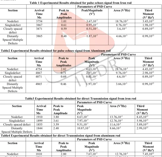
Table 1 Experimental Results obtained for pulse echoes signal from Iron rod Parameters of PSD Curve
Section Arrival Time Ms Peak to Peak Amplitudes PeakMagnitude
(V2) Area (V
2Hz) Third
Moment (V2Hz4)
Nodefect 3754 1.01 3.67ₓ10-7 18.76ₓ10-3 3.45ₓ1015
Singledefect 3867 0.61 0.97ₓ10-7 8.76ₓ10-3 1.98ₓ1015
Closely spaced
defect 3871 0.59 0.51ₓ10
-7 3.6ₓ10-3 0.89ₓ1015
Distantly Spaced Multiple
Defects
3865 0.48 1.87ₓ10-7 4.66ₓ10-3 0.99ₓ1015
Table2 Experimental Results obtained for pulse echoes signal from Aluminum rod
Parameters of PSD Curve
Section Arrival Time Ms Peak to Peak Amplitudes Peak Magnitude
(V2)
Area (V2Hz) Third
Moment (V2Hz4)
Nodefect 4754 2.02 4.67ₓ10-7 28.76ₓ10-3 4.45ₓ1015
Singledefect 4867 0.71 2.97ₓ10-7 9.76ₓ10-3 2.98ₓ1015
Closely spaced
defect 4871 0.69 0.61ₓ10
-7 4.6ₓ10-3 0.89ₓ1015
Distantly Spaced Multiple
Defects
4865 0.46 1.97ₓ10-7 3.66ₓ10-3 0.99ₓ1015
Table3 Experimental Results obtained for direct Transmission signal from iron rod Parameters of PSD Curve
Section Arrival Time Ms Peak to Peak Amplitude Peak Magnitude (V2)
Area (V2Hz) Third
Moment (V2Hz4)
Nodefect 1910 3.80 8.67ₓ10-7 13.76ₓ10-3 8.45ₓ1015
Singledefect 1899 3.61 7.97ₓ10-7 12.76ₓ10-3 5.98ₓ1015
Closely spaced defect 1855 3.59 9.51ₓ10-7 11.6ₓ10-3 5.89ₓ1015
Distantly
Spaced Multiple Defects 1844 2.48 10.87ₓ10
-7 8.66ₓ10-3 2.99ₓ1015
Table4 Experimental Results obtained for direct Transmission signal from aluminum rod Parameters of PSD Curve
Section Arrival Time Ms Peak to Peak Amplitudes Peak Magnitude
(V2)
Area (V2Hz) Third
Moment (V2Hz4)
Nodefect 1810 2.80 7.67ₓ10-7 12.76ₓ10-3 7.45ₓ1015
Closely spaced
defect 1755 2.59 8.51ₓ10
-7 10.6ₓ10-3 4.89ₓ1015
Distantly Spaced Multiple
Defects
1744 1.48 9.87ₓ10-7 8.66ₓ10-3 1.99ₓ1015
200mm
Fig.2 Dimension of test sample
Fig.3 Detected defect and their location on test sample
Fig.4Nonlinear detection of defect
P2
P3
+C
+D
+B
+A
+G
+F
+E
+H
Magnitude (Arbitrary
Units)
Scan Position(mm)
Fig.5 Measuredmagnitudes of defect echoes and through signal 4. CONCLUSION
Non destructive testing and evaluation by ultrasonics method is very widely applied to all the industries in production and maintenance. Its application to the newly developed material needs great attention. The developments of light weights, high strength and stiff materials have been of particular interest to material scientists and aero-space technologists. These fibers reinforced composite materials are being used as structures for defense, space commercial application. Attempt are being made to detect and characterize foreign inclusions and defects by UT scanning, imaging and signals analysis system to produce defect-free material. Ultrasonic evaluation of super-conducting ceramic material need further research for perfection.The result observed compared with known values of artificial defects. We found that defects location detected for ultrasonics is closing agreement to the actual results. The result from the spectral analysis is tabulated in table1&2 the nearness of defect caused lost 40%to 70% in the amplitudes if the backwall echoes for the different condition. The rate drop in the amplitudes of back divider echoes was higher for painted bar when contrasted and the rusted pillar. Little deployments (up to 1.2%) are found in the entry time of back divider echo for defect pillars. Pinnacle extent, region and third minute (essential of result of PSD and solid shape of frequencies) parameters of Power Spectral Density (PSD) bend comparing to the back divider echoes demonstrated a drop of half to 90%.It tends to be seen from Table 3 &4 that the landing times of sign show just an increase of not exactly press 0.5% because of nearness of defects. A direct transmission test was performed on a 0.5m long iron and aluminum pole with a defect over the width. Sign were required through the defect area with and without paint in the defect.
6. REFERENCE
1. Auld, B.A., Acoustic Fields and Waves in Solids, Vol I & II, 2nd edition Krieger Publishing Company, February 1990; ISBN: 089874783X
2. Cartz, Louis, Nondestructive Testing: Radiography, Ultrasonics, Liquid Penetrant, Magnetic Particle, Eddy Current, ASM Intl; ISBN: 0871705176
3. Krautkramer, Josef and Krautkramer, Herbert, Ultrasonic Testing of Materials, 4th/revised edition, Springer Verlag, November 1990, ISBN: 0387512314 M. Berke, U. Hoppenkamps: "Testing materials ultrasonically" Krautkrmer Training System, Level 1 3rd edition (1990)
4. M. Berke, U. Hoppenkamps: "Testing materials ultrasonically" Krautkramer Training System, Level 2 3rd edition (1986)
5. 9M. Berke, U. Hoppenkamps: "Practical training with digital ultrasonic instruments". Krautkramer Training System, Part 4 3rd edition (1992)
6. M. Berke:"Thickness measurement with ultrasonics" Krautkramer Training System, Part 5 2nd edition (1992) This edition is only available in German.
7. H.-W. Corsepius: "Nondestructive testing of materials using ultrasonics, introduction to basics" Special Issue 218 (1990) Krautkramer GmbH & Co.
8. J. and H. Krautkramer: "Ultrasonic testing of materials" 4th edition (1990) Springer-Verlag 9. D. Ensminger and L.J. Bond, Ultrasonics, 3rd ed., 2011, CRC Press
10. “Codes and Standards Bodies Involved in NDT Industry,” ASNT,www.asnt.org/ MajorSiteSections/NDT-Resource-Center/ Codes_and_Standards/Codes_and_Standard_ Bodies.aspx (accessed Jan. 20, 2018)
11. P.C. Miedlar, A.P. Berens, A. Gunderson, and J.P. Gallagher, “Analysis and Support Initiative for Structural Technology (ASIST); Delivery Order 0016: USAF Damage Tolerant Design Handbook: Guidelines for the Analysis and Design of Damage Tolerant Aircraft Structures,” AFRL-VA-WP-TR-2003-3002, 2003
12. M. Farley, 40 years of progress in NDT – History as a Guide to the Future, Proc. 40th Annual Review of Progress in Quantitative Nondestructive Evaluation, AIP Conf. Proc., Vol 1581, 2014, p 5–12
14. I.A. Viktorov, Rayleigh and Lamb Waves, Springer, 1967