29
Dynamic Effect Analysis And Flexural Storage
Modulus Optimization Of CFRP Hybrid Nano
Composites Using RSM
Shailesh D. Ambekar, Vipin Kumar Tripathi, Huynh Tan Hoi
Abstract: In the last few years, due to the enhancement in the properties of CFRP with the presence of nano particles, the interest is increased in studying the use of CFRP hybrid nanocomposite In this paper, the effect and evaluation of mixing of nano clay nanoZnO particles and carbon fiber plies angle orientation on dynamic mechanical properties laminates of CFRP were studied.A hand layup method followed by process of vacuum bagging was used to make the samples of composite. Dynamic mechanical analyzer (DMA) was used to inspect the dynamic mechanical properties of CFRP hybrid nanocomposite specimens with changing temperature. The response surface methodology is used for design of experiments by considering the percentage of weight of nanoclay , nanoZnO and fiber orientation angle as an independent variables and storage modulus due to the flexural loading is used as response. The optimization of the storage modulus is carried out with RSM response optimizer and optimum value of storage modulus is found.
Keywords: Dynamic mechanical analysis (DMA);Response surface methodology (RSM);hybrid nanocomposite; nanoclay; nanoZnO
————————————————————
1. INTRODUCTION
FRP hybrid nano composites combine two or more types of nano particles as additional reinforcement in a matrix. The composites mechanical properties are dependent on the properties of matrix, reinforcement fiber and the interaction of nano particles with them. So, making of FRP hybrid nanocomposites gives improved mechanical properties as compared to the conventional composites with reduced costs. Carbon fiber is most favorite reinforcement for composite structures due their capacity to advance the mechanical properties and tribological of polymer composites, also, carbon fiber has outstanding thermal stability, Young’s modulus, superior strength, healthier thermal conductivity, and exceptional electrical properties than other fibers [1-3]. FRP composites are used in various applications where elevated mechanical properties are required, such as automobile, aerospace etc. Deca et al establish that there is improvement in the UV resistance and thermal stability in the polymers of wood with the inclusion of nanoZnO and nanoclay[4]. Rashmi , et al. and Li Chang et al. presented work on the improvement in the wear resistance of regular size and short carbon fiber composites in addition of nano particles. [5,6]. M.A. Shazed and A.R. Suraya showed that The CNT are also supportive in enhancement of mechanical properties of CFRP composites, when coating of h CNT applied with different fiber orientations [7].As per David A. Hawkins et al presented that the significance of the nanoparticles on the upgrading the toughness of CFRP composites [8] The astonishing mechanical, thermal and electrical properties of carbon nano tubes and nanoZnO have provoked researches to make use of them as a filler in composite in order to perk up the properties of the parent matrix[9,10]. In the study by Declan Carolana et al discussed that the nanoparticles are eagerly transferable to a toughness increase in the interlaminar fracture energy of the CFRP composite laminates [11]. With addition of nanoclay, the glass transition temperature can be increased as compared to neat CF/PPc composite demonstrating improved heat resistance and improved themo mechanical properties with addition of organoclay as per the work of Mohamed H. et al [12]. Also many researchers have enlisted the effect of
on flexural properties of ordered Copper foam [33]. There are many optimization algorithms which have been used in different problems. Guangran Zhang and E. H. Chimowitz have used a Markov Chain-Monte Carlo algorithm for Energy network optimization [34]. In this paper the effective dynamic analysis of the CFRP hybrid nanocomposites for the storage modulus under flexure is experimentally studied. The design of experiment is prepared by with CCD(Central composite design)the part of response surface methodology, which has been employed to develop the function of physical factors in terms of mathematical models to predict DMA performance of hybrid CFRP nanocomposite and also used to present a the optimum design of new CFRP hybrid nanocomposite. Experimental
(A) (B)
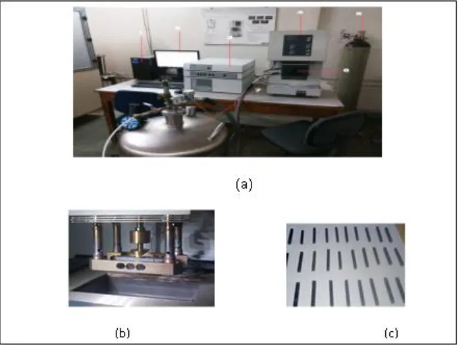
Fig. 1: (a) Hand Lay up of CFRP,(b) Vacuum Bagging
2.1. Details of Material
For the experiments in this evaluation CFRP epoxy composites treated as controlled sample. The unidirectional carbon fibrics having standard modulus 3K of 200 GSM ,code HCU200. The rsin named Hinpoxy C,which is Bisphenol -A based liquid resin along with the amine modified hardener known as Hinpoxy hardener-B is a colorless, and low viscosity liquid with stoichiometric ratio of A:B=10:3 was used. Resins, hardener along with carbon fiber ,supplied from the Hindoostan Mills Ltd. Mumbai, India. The nanoclay was montmorillonite, modified surface with layers of Aluminosillicate (approximately thickness of 1
nm), and Sp Gra. 2.6. Zinc oxide -ZnO nanoparticles, with Purity of 99.9%, SSA: 20-60 m2/g, with Particles Size: 30-50nm, Morphology: nearly spherical, True density: 6 g/cm3 density for Bulk: 0.28 - 0.48 g/cm3 were used, supplied from Nano Research Lab. Jamshedpur, (Jharkhand),India [30].
2.2. Fabrication of composites
31 Fig.2: (a) DMA 242 E Artemis set up,(b) Specimen Holder in DMA setup, (c) Specimens of coded units
3. DYNAMIC MECHANICAL ANALYSIS (DMA)
DMA is an extensively used method to determine the effect of temperature on the properties of damping and various moduli of materials by application of sinusoidal force. Modulus is calculated in the 2 parts, these are storage modulus , E’ and loss modulus, E”. The relation of loss modulus to the storage modulus is known as mechanical damping (given by tan δ is a dimensionless number) it gives the energy lost or can also be expressed in form of recoverable energy. The higher tan δ value is indicates that material has higher nonelastic strain, while lower δ shows that material is more elastic. Storage modulus elaborates the elastic behavior of the CFRP and which is proportionate to the energy stored in one cycle, while loss modulus gives the viscous properties of material, which is proportionate to energy dissipated in one cycle, The phase angle, δ which is the phase difference between the dynamic stress and strain of viscoelastic material under the effect of sinusoidal oscillation. This dynamic mechanical test is used to derive the viscoelastic and elastic behaviors of CFRP hybrid nanocomposites sample with the sinusoidal force application. The thermal analyses were completed by using a DMA242E analyser (Netzsch, Germany) in a mode of three-point-bending with the oscillation of 1 Hz (as shown in
Fig. 2.(a) ). The storage modulus (E’) ,damping factor (tanδ) and loss modulus (E”) of each CFRP hybrid nanocomposite sample were determine under the subsequent conditions: a temperature range from 400C up to 1500C at rate of heating of 30C/min, as a cooling agent the liquid nitrogen is used by putting in the machine fixture (as shown in Fig. 2.(b) ). The samples were sized in 40 mm in length and 4 mm in width, while the thickness were around 3.2 mm(as shown in Fig. 2.(c) ).
4 .EXPERIMENTAL DESIGN
The experimental design was done by using the RSM, RSM (Response surface methodology) is the techniques for multidimensional mapping of response patterns for different levels of factors that are used to direct physical processes. RSM makes use of regression analysis of the data from several levels experiments carried out and can be applied to find approximate minimum or maximum points in response. In recent era, RSM played an important job in various fields like nanotechnology, biotechnology, etc. One of the abilities of RSM is used to develop a correct efficient model between output response (Y) and set of independent variables.
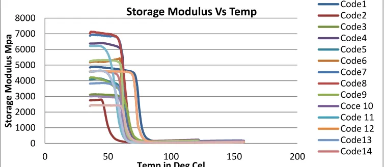
Fig. 3: Graph showing the effect of temp on storage modulus of the CFRP hybrid nano composites coded samples
Fig.4: Graph showing the effect of temp on loss modulus of the CFRP hybrid nanocomposites coded samples 0
1000 2000 3000 4000 5000 6000 7000 8000
0 50 100 150 200
Sto
rag
e
M
o
d
u
lu
s
M
p
a
Temp in Deg Cel
Storage Modulus Vs Temp
Code1Code2Code3 Code4 Code5 Code6 Code7 Code8 Code9 Coce 10 Code 11 Code 12 Code13 Code14
0 500 1000 1500 2000
0 50 100 150 200
Loss M
o
d
u
lu
s i
n
M
p
a
Temp in Deg Cel
The following equation gives the value of Y
Y= β0+β1X1+β2X2+………+βkXk + ε
(1)
Where X1, X2…………..Xk are process independent
variables and β0 is constant coefficient, ε is the observed
error and βk is the coefficient factor in the system. This
second order polynomial model, if there is form of curvature will be displayed as
∑ ∑ ∑ (2)
In this experiment the software of Minitab was used to interpret and analyze the data processing and to obtain results. To design of experiments CCD was chosen. Here the input variables were nanoZnO wt%, nanoclay wt% and fiber orientation angle and the response was the storage and loss modulus[30].
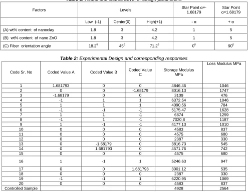
Table 1: Actual and Coded Level of design parameters
Factors Levels Star Point α=-1.68179 α=1.68179 Star Point
Low (-1) Center(0) High(+1) - α + α
(A) wt% content of nanoclay 1.8 3 4.2 1 5
(B) wt% content of nano ZnO 1.8 3 4.2 1 5
(C) Fiber orientation angle 18.20 450 71.20 00 900
Table 2: Experimental Design and corresponding responses
Code Sr. No Coded Value A Coded Value B Coded Value C
Storage Modulus MPa
Loss Modulus MPa
1 1.681793 0 0 4846.46 1046
2 0 0 -1.68179 8016.13 1747
3 -1.68179 0 0 3109 476
4 -1 1 1 6372.54 1046
5 1 1 1 4090.56 784
6 -1 -1 -1 5175.47 1628
7 1 1 -1 6874 1259
8 -1 1 -1 7020.8 1187
9 1 -1 -1 4177.13 1010
10 0 0 0 4583 837
11 0 0 0 4575 680
12 0 0 0 2387 330
13 0 -1.68179 0 3816.73 545
14 0 1.681793 0 4571.76 742
15 0 0 0 4575 680
16 1 -1 1 5246.63 947
17 0 0 1.681793 3001.12 535
18 0 0 0 2387 330
19 -1 -1 1 6220.95 1069
20 0 0 0 4583 837
Controlled Sample 4928 2564
5. RESULTS AND DISCUSSION
5.1 Overall effect of temperature increase on modulus of storage and loss
In the Figure 3 and 4 it can be seen that how is the behavior of the storage and loss modulus of the coded specimen of CFRP hybrid nanocomposites. Storage modulus gives value for the stiffness of a viscoelastic material, which is proportionate to the energy stored during one loading cycle. It is around equal to the elastic modulus for a reversible deformation and rapid stress at low load .Loss modulus gives the value proportionate to energy dissipated in the form of heat during one loading cycle. It is vibration energy that which transformed during vibration and that cannot be recovered. Modulus value is expressed in MPa, It is found that the value of the value of storage modulus is increased upto 40% and the loss modulus is
improved by almost 35% as shown in the table in the code number 2 sample. The detailed analysis of the values of storage modulus and its variance is calculated and studied the effects of various independent variables by using RSM.
5.2 Analysis and modeling for storage modulus using RSM
33
Minitab software. The actual and coded Level of design parameters is as per the Table 1.
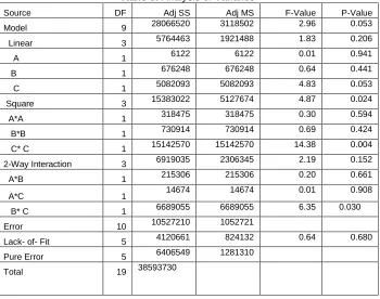
5.2.1. Analysis of variance (ANOVA) and fitting regression model.
By considering the level of parameters as shown in the Table1,the corresponding experimental design and the values of response is displayed in the Table 2. Accordingly when the analysis of variance is carried out for the given set of the results, which is displayed in the Table 3.Then the regression equation derived from using the coefficents in
the ANNOVA table 3 is given by Eqn.1. Fig5 (a) shows the graph of residual for normal probability, which demonstrate, is the collected data and allows the fits of distribution. When most of points in data fall nearby to the fitted line for distribution, the model is best suited for the said results. In this Fig 5 (a), the points plotted were falling nearer to the fitted line of distribution, so the distribution of storage modulus was closer to the normal distribution. Graph of residuals Vs fitted point values for ANOVA in Figure 5 (b) which indicates that the residuals were scattered randomly for the analysis, so it can establish that there is no any violation of hypothesis and proposed model was satisfactory [30].
Table 3: Analysis of Variance
Source DF Adj SS Adj MS F-Value P-Value
Model 9 28066520 3118502 2.96 0.053
Linear 3 5764463 1921488 1.83 0.206
A 1 6122 6122 0.01 0.941
B 1 676248 676248 0.64 0.441
C 1 5082093 5082093 4.83 0.053
Square 3 15383022 5127674 4.87 0.024
A*A 1 318475 318475 0.30 0.594
B*B 1 730914 730914 0.69 0.424
C* C 1 15142570 15142570 14.38 0.004
2-Way Interaction 3 6919035 2306345 2.19 0.152
A*B 1 215306 215306 0.20 0.661
A*C 1 14674 14674 0.01 0.908
B* C 1 6689055 6689055 6.35 0.030
Error 10 10527210 1052721
Lack- of- Fit 5 4120661 824132 0.64 0.680
Pure Error 5 6406549 1281310
Total 19 38593730
Model Summary
S R-sq R-sq(adj) 1026.02 82.72% 68.17%
Regression Equation in Uncoded Units
Fig. 5: (a) Normal probability plots for residuals, (b) Residual Vs fitted values (c) Main effect plot of designed factors for storage modulus
increased from 1% to 2% wt of the nano clay and get decreased between wt 2% to 3% of nanoclay and again gives increase trend in between 3% to 4.2%. Also it is observed the similar kind of trend in the case of storage modulus with the effective addition of nano ZnO While storage modulus is getting decrease with increase in degree of fiber orientation from 00 to 450, again it is get
increased from 450 to 720 and declines after this level. So it was observed from the main effect plot that there is direct effect of nanoclay and nanoZnO on storage modulus, while fiber orientation had reverse effect on storage modulus From plots, it can be consummate that all results were in approved with what observed in the ANOVA tables and fitted regression coefficients.
Fig. 6: Storage modulus interaction plot for data means
5.2.2 Plot of Interaction for storage modulus
Figure 6 gives the two way interaction between the input variable and its effect on the storage modulus as response As per the left hand graph at corner, shows the interaction between weight % of nanoclay and nanoZnO on the storage modulus falls in the lower series of its range value, it deviates in the smaller range of value on Y axis. For interaction effects between weight % of nanoclay and fiber orientation angle effectively changes the storage modulus value at higher range. Similar kind of trend can be observed for the of interaction effect amongst the wt. percentages of nanoZnO and fiber angle of orientation in right hand corner graph.
5.3 Contour and surfaces graph plots for the storage modulus of CFRP hybrid nano composite
In the part of contour 2D plots and surfaces3D graphs for the effect of various parameters on the storage modulus of CFP hybrid nanocomposites are explained storage modulus
by putting all other factors and parameters should be held constant or fixed at zero level. These graphs are useful for exploring the sound effects of factors for interaction plots and main effects on response.
5.3.1 Effect of nanoclay and nanoZnO on storage modulus of CFRP hybrid nanocomposites
Fig. 7 (a) and (b) shows the contour and surface graphs for nanoclay and nanoZnO and by considering value of fiber orientation angle fixed at 450as zero level. The contour plot displays that the value storage modulus is decreasing with increase in nanoclay wt% .Similarly the value of storage modulus is increasing with the nanoZnO wt%, from the contour plot it can be seen that the maximum storage modulus can be obtained at highest content of both nano particles. As both the variables illustrate has clear effect on response at the same time and so that the interaction between these variables shows the effect on storage modulus.
(a) (b)
35 5.2.2 Effect of nanoclay and fiber orientation angle on
the storage modulus
By fixing or holding the value of nanoZnO at zero level (ie at 3%), we can get read of contour graph and surface graph for fiber angle of orientation and nanoclay wt % as shown in Fig.8 (a) and (b) respectively. As shown in this plots, value of storage modulus is not much varied with
change in wt % of the nanoclay but get decreases with increased in value of fiber angle of orientation up to 45 degrees and again increasing towards the end. Furthermore it is noticeable that by altering in the worth of both the variables at the same time affect on storage modulus, after that there was a communal interaction between fiber angle of orientation and nanoclay% wt .
(a) (b)
Fig. 8: (a) 2-Dcontour and (b) 3-D surface plots for effect of nanoclay and Fiber orientation angle on storage modulus
(a) (b)
Fig. 9 :(a) 2-Dcontour and (b) 3-D surface plots, for effect of nano ZnO and Fiber orientation angle on storage modulus
5.3.3. Effect of nanoZnO and fiber orientation angle on storage modulus
Fig.9. (a) and (b) displays contour 2D graph and surface 3D plot for nanoZnO wt % with fiber orientation angle, by keeping nanoclay wt% was fixed at 3% as zero level.. As per the surface plot, storage modulus get decreases with increment in value of fiber angle of orientation, simillerly the storage modulus increases with upgrading in wt % of nanoZnO. It can be seen that prudent values storage modulus can be obtain for the lower range of fiber angle orientation and higher nanoZnO wt %. The maximum obtained value for storage modulus was 8016.13 MPa which was in No. 02 coded level run with nanoclay = 0, fiber orientation angle = -1.68179 and nanoZnO = 0, the equivalent real values were nanoclay = 3%, fiber angle of orientation equal to 00 and nanoZnO = 3% respectively.
5.4 Optimization of storage modulus
In the part of optimization, the optimum value of flexural storage modulus was obtained by using Minitab response optimizer. For this step the highest value for flexural storage modulus was presumed at 12000 MPa, and consequent value got from the minitab was 11993.51 MPa and related values for nanoclay, nanoZnO and fiber orientation angle were 5wt%, 5 wt% and 00 respectively. Accordingly the specimens were fabricated and tested to get experimental values of the flexural storage modulus for optimized combination and the average value of flexural storage modulus 11899 MPa was obtained.
6. CONCLUSION
Response surface methodology is used for design of experiments, modeling and the prediction of the optimum design. It is seen that the model presented was able to predict the 82% of the response ie storage modulus. The analysis of variance shows the direct effect of nanoZnO and nanoclay, fiber orientation angle on the storage modulus. While going through the graph of storage and loss modulus of coded samples, It is observed that the value of storage modulus is increased up to 40% and the loss modulus is improved by almost 35%. In the optimization stage the targeted storage modulus was 12000 MPa, obtained value from the software of Minitab was 11993 MPa, the actual obtained value after experiments was 11899 Mpa, which occurred at corresponding values for nanoclay, nanoZnO and fiber orientation angle were 5wt%, 5 wt% and 00 respectively The optimum value of the storage modulus is improved up to 90% or almost doubled from the controlled sample.
ACKNOWLEDGEMENT:-
The above work is funded by the Departmental R&D funds from the Mechanical Engineering, Dept. College of Engineering, Pune, (MS), India
REFERENCES
[1] M.H.G Wichmann, U. Kopke , B. Fiedler a K. Schulte , Carbon nanotube-reinforced epoxy-composites: enhanced stiffness and fracture toughness at low nanotube content, Composites Science and Technology 64 (2004) 2363–2371.
[2] Md Ekramul Islam, Tanjheel H. et al., Characterization of Carbon Fiber Reinforced Epoxy Composites Modified with Nanoclay and Carbon Nanotubes, Procedia Engineering 105 ( 2015 ) 821 – 828.
[3] K.S. Harishanand, H. Nagabhushana,et al, Comparative Study on Mechanical Properties of ZnO, ZrO2 and CeO2 Nanometal Oxides Reinforced Epoxy Composites, Advances in Polymer Science and Technology: An International Journal 2013; 3(1): 7-13. [4] Biplab K. Deka, Tarun K Maji, Effect of Nanoclay and
ZnO on the Physical and Chemical
[5] Properties of Wood Polymer Nanocomposite, Journal of Applied Polymer Science, Vol. 124, 2919–2929 (2012).
[6] Rashmi , N.M. Renukappa , B. Suresha , Dry sliding wear behaviour of organo-modified montmorillonite filled epoxy nanocomposites using Taguchi s techniques,Materials and Design 32 (2011) 4528– 4536.
[7] Li Chang , Klaus Friedrich, Enhancement effect of nanoparticles on the sliding wear of short fiber-reinforced polymer composites: A critical discussion of wear mechanisms, Tribology International 43 (2010) 2355–2364.
[8] M.A. Shazed , A.R. Suraya , S. Rahmanian , M.A. Mohd Salleh., Effect of fibre coating and geometry on the tensile properties of hybrid carbon nanotube coated carbon fibre reinforced composite, Materials and Design 54 (2014) 660–669.
[9] David A. Hawkins Jr., Anwarul Haque, Fracture toughness of carbon-graphene/epoxy hybrid Nan
ocomposites- Procedia Engineering 90 ( 2014 ) 176 – 181.
[10] Ayoub Yari Boroujeni, Marwan Al-Haik, Anahita Emami, and Roozbeh Kalhor, Hybrid ZnO Nanorod Grafted Carbon Fiber Reinforced Polymer Composites Composites; Randomly versus Radially Aligned Long ZnO Nanorods Growth- Journal of Nanoscience and Nanotechnology Vol. 18, No.6, 4182-4188, 2017. [11] Suma Ayyagari, Marwan Al-Haik and Virginie Rolli,
Mechanical and Electrical Characterization of Carbon Fiber/Bucky Paper/Zinc Oxide Hybrid Composites, journal of Carbon Research, C 2018, 4, 6; doi:10.3390/c4010006,1-18.
[12] Declan Carolana, A.J. Kinlocha, A. Ivankovicb, S. Sprengerc, A.C. Taylora., Mechanical and fracture performance of carbon fiber reinforced composites with nanoparticle modified matrices, Procedia Structural Integrity 02 (2016) 096–103.
[13]Mohamed H. Gabr, Wataru Okumura, Hisai Ueda, Wataru Kuriyama, Kiyoshi Uzawa, Isao
[14]Kimpara, Mechanical and thermal properties of carbon fiber/polypropylene composite filled with nano-clay, Composites: Part B 69 (2015) 94–100.
[15]Chuanbao Wang and Sanjiu Ying,Thermal, Tensile and Dynamic Mechanical Properties of ShortCarbon Fibre Reinforced Polypropylene Composites, Polymers & Polymer Composites, Vol. 21, No. 2, 2013.
[16]Suma Ayyagari, et al. Mechanical and Electrical Characterization of CarbonFiber/Bucky Paper/Zinc Oxide Hybrid Composites, Journal of Carbon Research,C 2018, 4, 6; doi:10.3390/c4010006.
[17]Michelle LealiCosta, Edson CocchieriBotelhoa, Jane Maria Faulstich de Paivaa, Mirabel CerqueiraRezendea*, Characterization of Cure of Carbon/Epoxy Prepreg Used in Aerospace Field, Materials Research, Vol. 8, No. 3, 317-322, 2005. [18]Kaka1, J. Rongong2, A. Hodzic3, C. Lord, Dynamic
mechanical properties of woven carbon fibre reinforced thermoplastic composite materials, university of Sheffield http:// eprints. whiterose.ac.uk/96135
[19]Dana Luca Motoc1, Santiago Ferrandiz Bou2 andRafael Balart Gimeno, Effects of fibre orientation and content on the mechanical, dynamic mechanical and thermal expansion properties of multi-layered glass/carbon fibre-reinforced polymer composites, Journal of Composite Materials2015, Vol. 49(10) 1211– 1221
[20]Sandi G. Miller, Paula J. Heimann and Daniel A. Scheiman, Evaluation of Nanomaterial Approaches to Damping in Epoxy Resinand Carbon Fiber/Epoxy Composite Structures by Dynamic Mechanical Analysis, NASA/TM—2013-217887.
[21]M. B. A. Salam, M. V. Hosur, S. Zainuddin, S. Jeelani, Improvement in Mechanical and
[22]Thermo-Mechanical Properties of Epoxy Composite Using Two Different Functionalized Multi-Walled Carbon Nanotubes, Open Journal of Composite Materials, 2013, 3, 1-9
37
Functionalized Multi-Walled Carbon Nanotubes, Polymers & Polymer Composites, Vol. 21, No. 8, 2013 [24]Hasan Yavuz Unal, Gulşah Oner, Yeliz Pekbey,
Comparison of the Experimental Mechanical Properties and DMA Measurement of Nanoclay Hybrid Composites, European Mechanical Science 2018, Vol. 2(1): 31-36
[25]Volker Altstaedt, Philipp Werner, Jan Sandler, Rheological, Mechanical and Tribological Properties of Carbon-nanofibre Reinforced Poly (ether ether ketone) Composites, Polímeros: Ciência e Tecnologia, vol. 13, nº 4, p. 218-222, 2003
[26]P. Surya Nagendra1, V.V.S. Prasad1, Koona Ramji, A Study on Dynamic Mechanical Analysis of Natural Nano Banana Particle Filled Polymer Matrix Composites, Materials Today: Proceedings 4 (2017) 9081–9086
[27]Hariharasudhan S1, Balaji A P2, Sathishkumar K S3, Yuvaraj K4, Mechanical Behavior and Dynamic Mechanical Analysis Study on Nanoclay Filled Carbon-Epoxy Composites, IJIRSTE, Volume 5, Special Issue 7, April 2016
[28]Sasan Nouranian, Hossein Toghiani, Thomas E. Lacy,Charles U. Pittman, Jr.Janice Dubien, Dynamic mechanical analysis and optimization of vapor-grown carbon nanofiber/vinyl ester nanocomposites using design of experiments, Journal of Composite Materials, 45(16) 1647–1657.
[29]Yasser Rostamiyan , Abdolhossein Fereidoon, etal. Using response surface methodology for modeling and optimizing tensile and impact strength properties of fiber orientated quaternary hybrid nano composite, Composites: Part B 69 (2015) 304–316.
[30]Y.Rostamiyan , A. Fereidoon, Experimental study and optimization of damping properties of epoxy-based nanocomposite: Effect of using nanosilica and
high-impact polystyrene by mixture design approach, Materials and Design 65 (2015) 1236–1244
[31]Rostamiyan , Abdolhosein Fereidoon, et al, Experimental and optimizing flexural strength of epoxy-based nanocomposite: Effect of using nano silica and nano clay by using response surface design methodology, Materials and Design 69 (2015) 96–104. [32]R. Satheesh Raja, K.Manisekar , Experimental and
statistical analysis on mechanical properties of nano fly ash impregnated GFRP composites using central composite design method, Materials and Design 89 (2016) 884–892.
[33]Shailesh D. Ambekar · Vipin Kumar Tripathi, Optimization of flexural strength of CFRP hybrid nano composites containing nanoZnO and nanoclay particles International Journal on Interactive Design and Manufacturing , https://doi.org/10.1007/s12008-019-00539-w.
[34]V.K.Tripathi, N. S. Kulkarni, OptiComp: A Comprehensive Procedure for Optimal Design of a Composite Laminate, Int. J. of Engg. Sciences, , ISSN: 0976 – 6693, Vol. 8(2), 2014, pp. 110 -120.
[35]Experimental evaluation of different fillers in dental composites in terms of mechanical properties’, U. V. Hambire and V. K. Tripathi, ARPN Journal of Engineering and Applied Sciences, Vol. 7(2), 2012, pp. 147 – 151 .