Review
Protection Coordination of Properly Sized and Placed
Distributed Generations–Methods, Applications and
Future Scope
Sunny Katyara 1,*,Lukasz Staszewski 2 and Zbigniew Leonowicz 2,*
1 Sukkur IBA University, Airport Road, Delhi Muslim Housing Society, Sukkur, Sindh 65200, Pakistan 2 Faculty of Electrical Engineering, Wroclaw University of Science and Technology, W. Wyspianskiego 27,
50-570 Wroclaw, Poland; [email protected]
* Correspondence: [email protected] (S.K.); [email protected] (Z.L.); Tel.: +48-71-320-2626
Abstract: The radial distribution networks are designed for unidirectional power flows and are passive in nature. However, with the penetration of Distributed Generation (DG), the power flow becomes bidirectional and the network becomes active. The integration of DGs into distribution network creates many issues with: system stability, protection coordination, power quality, islanding, proper placement and sizing etc. Among these issues, the two most significant are optimal sizing and placement of DGs and their protection coordination in utility network. The proper coordination of relays with high penetration of DGs placed at optimal location increases the availability and reliability of the network during abnormal operating conditions.
This research addresses most of the available methods for efficient sizing and placement of DGs in distribution system (numerical, analytical and heuristic) as well as the developed protection coordination techniques for utility networks in the presence of DGs (Artificial Intelligence (AI), adaptive and non-adaptive, multi-agent, hybrid). This paper indicates the possible research gaps and highlights the applications possibilities and methods’ limitations in the area of DGs.
Keywords: Index Terms—Distributed Generation; protection coordination; optimal DG location; optimal DG sizing
1. Introduction
Distributed generation (DG) has gained enormous popularity due to its modularity, ease of deployment, operation and control. The term DG is given to the production of electricity near the load center. The decentralized nature of distributed generation makes the basis for micro-grids, where the concept of centralized generation and control does not exist anymore and leads to the smart grid solutions [1]. DG technology mostly involves Renewable Energy Sources (RES) and cogeneration. The integration of DGs into distribution network may pose both positive and negative impact depending upon the characteristics of distribution network and the DG itself. The positive impacts of DG installation are: power loss reduction, voltage profile and reliability improvement, power quality enhancement, no need of new transmission lines installation, and postponement of substation capacity upgrade [2]. Moreover, the DG does not contribute to the greenhouse gases providing clean and efficient energy. The negative effects of DG application are: fault current level increase, discoordination of protection schemes, islanding, bidirectional power flows, and transient instabilities [3].
The optimal size and location of incoming distributed generation are preliminary factors to maximize the system support benefits. The size and location of DG can be decided on the basis of enhancement of one or more distribution network parameters in a way to improve the energy
2 of 24
efficiency and reduction of negative impacts of the installation [4]. Optimal size and location of DG improves also the performance and operation of whole network. The additional power delivered by DG significantly affects the bus voltage, load characteristics and reliability of the system [5]. Therefore, at the planning stage of distribution system, one of the most crucial and difficult task is to estimate the capacity and location of futures in the network. Different techniques are used for such estimations (e.g., numerical, analytical, and heuristic) and all of them were analyzed in terms of the efficient placement and sizing of DGs.
Since the main function of protection schemes in distribution networks is to immediately isolate the faulty part of the system from the healthy one for the fault occurrence. Thus, mostly overcurrent relays are used in such networks as primary and backup protection. The coordination of overcurrent relays is arranged in such a way that if the fault is not cleared by the primary relay then it should be backed by another relay.
With the introduction of DGs, the existing schemes for distribution network protection become inactive. The intensity of this discoordination depends upon the type, size and location of installed DG [6]. Since the radial utility networks are designed for unidirectional current flows so are protection schemes. With the DG installation, the distribution network forms a closed loop and current flows in both directions thus the existing relays do not protect the system effectively during the faults. One of the possibilities of solving this problem is use of directional overcurrent relays that are able to discriminate between upstream and downstream current flows [7]. Another option is to reset the Time Multiplier Settings (TMS) and Plug Multiplier Settings (PMS) of relays after integration of each DG [8]. However, Distribution System Operators (DSOs) are not in favor of changing the relays settings or network configuration manually. Many adaptive, non-adaptive, multi-agent, Artificial Intelligence (AI), hybrid, etc. techniques are evolved for proper and efficient coordination of relays.
This research addresses most of the available methods for efficient sizing and placement of DGs in distribution system (numerical, analytical, and heuristic) as well as the developed protection coordination techniques for utility networks in the presence of DGs (Artificial Intelligence (AI), adaptive and non-adaptive, multi-agent, hybrid). This paper indicates the possible research gaps and highlights the applications possibilities and methods’ limitations in the area of DGs.
2. Methods for Location and Size of DG
The methods for location and sizing of DG are divided roughly into three categories: numerical, Analytical, and Heuristic.
2.1. Objectives
The objectives of different methods of Optimal Sizing and Location of DG (OSLDG) into distribution network include [9]:
(1) minimizing the power losses,
(2) enhancing the voltage profile of network, (3) increasing the reliability of network,
(4) improving the loading capacity of network on the basis of voltage constraints, (5) maximizing the economy of utility operator,
(6) maximizing the MVA capacity requirements of network.
2.2. Constraints
The single and multi-objective function of different methods of OSLDG involves many optimization variables with the following possible constraints [10]:
(1) power balance in the network, (2) fault level and thermal limits, (3) voltage limits,
(5) allowable number of DGs in the network, (6) power factor limits.
2.3. DG Technologies
The devices used for distributed generation include directly connected to the system rotating machines (induction or synchronous), as well as static and rotating devices, which are coupled to the network through electronic converters. Different DG technologies have various influences on the operation, control and stability of a system e.g., the inverter based DGs inject harmonics into the system while the rotating machines create issues for the protection coordination in the distribution network [11]. Most of the effects of distributed generation technologies depend solely upon the size and location of DG installation in the utility network.
2.4. Numerical Methods
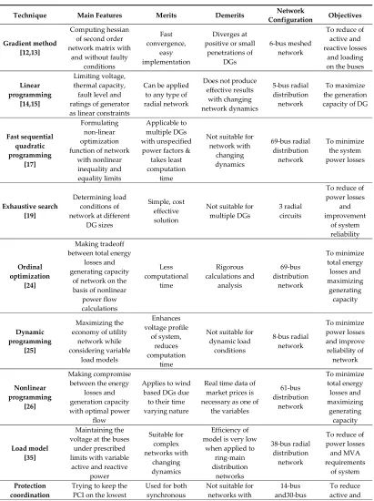
Numerical methods are based on mathematical programming and analysis and they are listed below. The summary of presented methods is gathered in Table 1.
(1) Gradient search—this method, proposed in [12,13], is used to find the proper size of DGs in mesh networks while considering and ignoring the short circuit capacity limits of the network. (2) Linear programming—this method, evolved in [14,15], is used to find the optimal location of
DG in the distribution network with maximum allowable penetration and energy harvesting from DGs.
(3) Sequential Quadratic Programming (SQP)—it is a second order differential technique, presented in [16], [17], and [18], is used to find the optimal location and size of multiple DGs in distribution network, without considering the short circuit capacity limits of network. The main objective is to reduce overall power losses in the network.
(4) Exhaustive search—a multi-object technique, used in [19–22], used for finding proper location and size of DGs with main focus on reliability improvement and loss minimization at fixed and variable load models. The time-varying behavior of renewable sources and loads were considered in [23].
(5) Ordinal optimization—this method, suggested in [24], is used to find the optimal location and size of DGs in the distribution network making compromise between the power losses minimization and maximizing the allowable penetration of DGs.
(6) Dynamic programming—this method’s used to find the optimal size and location of multiple DGs, main objective is to maximize the economy of utility operator at different loading conditions [25].
(7) Nonlinear programming—this technique converts probabilistic model with all network constraints into deterministic model using optimal load flow [26–28]. Mixed-Integer Non-Linear Programming (MINLP) is especially used for proper placement of multiple wind units simultaneously and can also be used for other types of DG but only for single units [29]. An interior point technique is used to find the maximum capacity of utility network for DG integration through optimal load flow analysis [30]. MINLP is used to determine the optimal location and size of inverter based DGs with main objective of enhancing the voltage stability margin of the network [31]. MINLP is used in [32,33] to determine the optimal location and size of DGs in distribution network while considering the variations in the market based energy prices. MINLP implemented in [34] is used during distribution system planning for investigation of the proper location and size of future DGs.
(8) Load model—this method is used to locate and size the DGs in a distribution network having constant and variable power flows. Load models have great significance in stability studies. Three different voltage dependent load models i.e., residential, commercial and industrial are considered for investigation [35].
4 of 24
represents the change of time coordination between the protection devices with change of penetration level of DGs into distribution network [36].
(10) Contingency analysis—this technique is used to analyze the impact of size and location of DG on distribution system after fault inception. Voltage profile of DG is investigated before and after the occurrence of fault to calculate voltage regulation of system. Based on loading conditions and network configuration the appropriate size and location of DGs can be decided [37,38].
Table 1. Summary of Numerical Methods for Placement and Sizing of DGs.
Technique Main Features Merits Demerits Configuration Network Objectives
Gradient method [12,13]
Computing hessian of second order network matrix with
and without faulty conditions Fast convergence, easy implementation Diverges at positive or small
penetrations of DGs
6-bus meshed network
To reduce of active and reactive losses
and loading on the buses
Linear programming
[14,15]
Limiting voltage, thermal capacity, fault level and ratings of generator as linear constraints
Can be applied to any type of radial network
Does not produce effective results with changing network dynamics 5-bus radial distribution network To maximize the generation capacity of DG
Fast sequential quadratic programming [17] Formulating non-linear optimization function of network
with nonlinear inequality and equality limits Applicable to multiple DGs with unspecified power factors &
takes least computation
time
Not suitable for network with changing dynamics 69-bus radial distribution network To minimize the system power losses Exhaustive search [19] Determining load conditions of network at different
DG sizes
Simple, cost effective solution
Not suitable for
multiple DGs 3 radial circuits
To reduce of power losses and improvement of system reliability Ordinal optimization [24] Making tradeoff between total energy
losses and generating capacity
of network on the basis of nonlinear
power flow calculations Less computational time Rigorous calculations and analysis 69-bus distribution network To minimize total energy losses and maximizing generating capacity Dynamic programming [25] Maximizing the economy of utility
network while considering variable load models Enhances voltage profile of system, reduces computation time
Not suitable for dynamic load conditions 8-bus radial network To minimize power losses and improve reliability of network Nonlinear programming [26] Making compromise between the energy
losses and generation capacity with optimal power
flow
Applies to wind based DGs due to their time varying nature
Real time data of market prices is necessary as one of
the variables 61-bus distribution network To minimize total energy losses and maximizing generating capacity Load model [35] Maintaining the voltage at the buses
under prescribed limits with variable
active and reactive power Suitable for complex networks with changing dynamics Efficiency of model is very low
when applied to ring-main distribution networks 38-bus radial distribution network
To reduce of power losses and MVA requirements
of system Protection
index
[36] level possible as the changes in penetration of DGs
affects the coordination timing
between the relays
and static DGs. Helps utility
operator to determine the
maximum amount DGs
that can be added to system
changing
parameters IEEE network reactive power losses, improve voltage profile
and restrict fault level and thermal limits
Contingency analysis
[37]
Estimating the network voltage profile before and after faults with and
without DGs
Suitable for network with
varying load conditions and
unbalanced power flows
Unreliable results
on upstream buses 37-bus IEEE network
To enhance voltage profile
of network
2.5. Analytical Methods
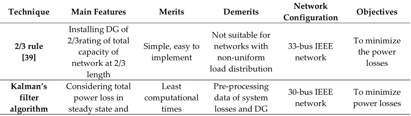
These methods are the combination of different techniques used to evaluate the characteristics of network qualitatively and quantitatively. Listed below techniques are based on mathematical expressions. The summary of presented methods is given in Table 2.
(1) 2/3 rule—applied for the distribution networks with uniformly distributed loads. The rule states, the incoming DG should have 2/3rd capacity of existing distribution network and should be installed at 2/3rd length of a line [39]. Non-effective for non-uniformly distributed loads. (2) Kalman’s filter algorithm—used for finding the optimal size of multiple DGs in combination
with Optimal Power Flow (OPF) technique [40]. OPF is used for finding the proper location of all the DGs in the distribution network,then Kalman’s filter is applied to find their suitable ratings.
(3) Loss sensitivity factor technique—used for calculation of the equivalent current injections of all DGs on the basis of load flow analysis and for determination of their proper size and location. It employs matrix algebra [41].
(4) Exhaustive load flow technique—based on the power factors of DGs being connected to the distribution network. The computational process is done twice: firstly for losses calculation and secondly for losses reduction [42].
(5) Improved analytical approach—based on the Improved Analytical (IA) expression and used for finding the optimal location and size of multiple DGs. The IA expression is formed by taking into account the active and reactive powers, and power factors of all the DGs [43].
(6) Exact loss formula—analytical method used for development of an expression incorporating the exact relation between the network losses with proper placement and sizing of DGs. Nonlinear curves are obtained between optimal place and size of DG and the network losses [44].
(7) Analytical approach with micro-generation—technique proposed in [45], based on the loss contribution of micro-generators in LV networks at different load conditions. Method used for determination of size, location and number of DGs to be installed in the network based on quantity of avoided losses.
Table 2. Summary of Analytical Methods for Placement and Sizing of DGs.
Technique Main Features Merits Demerits Configuration Network Objectives
2/3 rule [39]
Installing DG of 2/3rating of total
capacity of network at 2/3
length
Simple, easy to implement
Not suitable for networks with non-uniform load distribution
33-bus IEEE network
To minimize the power
losses Kalman’s
filter algorithm
Considering total power loss in steady state and
Least computational
times
Pre-processing data of system losses and DG
30-bus IEEE network
6 of 24
[40] sorting out the best samples from entire sets of DGs size and location
rating are required Loss sensitivity factor technique [41] Estimating the equivalent current
injections of DGs
Easy, fast with desired accuracy
Cannot be applied to multiple DGs
12, 34 and 69-bus radial network To minimize total power losses Exhaustive load flow technique [42] Executing load flow twice for loss
calculation and reduction and for
different configurations and power factors
of DGs Effective with variable load models Restricted to local minimum value
16, 33 and 69-bus radial networks To minimize total power losses Improved analytical approach [43] Maintaining balance of active
and reactive powers in the
network and analyze the optimal power factors of system
Can be used for any number of DGs and has
least computational times Protection coordination schemes becomes complex 16-bus, 33-bus and 69-bus radial networks To minimize total power losses Exact loss formula [44] Generating search tables for different combinations of
DGs and to analyze them by
exhaustive load flow
Can be applied to complex
networks
Not suitable for varying characteristics of network 30-bus, 33-bus and 69-bus radial networks To minimize total power losses Analytical approach with microgenera tion [45] Determining the amount of avoided losses on the basis of type of
load distribution and penetration of
micro-generation Highly recommended for practical used Cannot be applied to variable load models 34-bus distribution network To minimize total power losses
2.6. Heuristic Methods
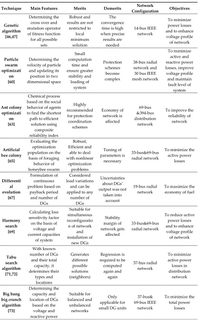
The heuristic methods are one of the optimization techniques, used to select the best possible solution among the set of different possible results. The summary of described methods is given in Table 3.
optimal location and size [56]. For maximizing the profits of consumers and suppliers GA is applied to find the proper size and location of DGs in distribution network [57]
(2) Particle swarm optimization—method based on natural phenomenon, inspired by social characteristics of bird flocking. The method has many similarities with genetic algorithm [58]. Based on the real and reactive powers injections of DGs, the PSO method is applied to find the proper location of DGs in distribution network [59], whereas based on the power factors of DGs, the PSO algorithm is applied to find the optimal location and size of DGs in distribution network at different load models [60]. Another possibility of considering the harmonic and protection coordination limit, the PSO algorithm is applied for finding the best location and size of rotating and static DGs [61].
(3) Ant colony optimization—method inspired by the behavior of ants which find shortest path to find food [62]. ACO algorithm suggested in [63], is used to find the optimal location and size of DGs while reducing network’s active power losses.
(4) Artificial bee colony—technique inspired by the behavior of honey bees called swarms that have intelligent foraging characteristics [64]. ABC algorithm was used in [65] for finding the optimal location and size of DGs on the basis of their power factors and active power losses of network.
(5) Differential evolution—an evolutionary algorithm which optimizes the results in steps on the basis of defined constraints. It may also optimize the objective functions that are not continuous in nature [66]. Based on the voltage sensitivity of buses, the DE is used to compute the best location and size of incoming DGs [67].
(6) Harmony search—a music based heuristic method inspired by the characteristics of music searching for the perfect state of harmony [68]. The problem evolved by loss sensitivity factor technique for determining the proper location of DGs is further solved with use of HS algorithm for finding their optimal sizes [69].
(7) Tabu search—mathematical optimization technique used to find the best possible solution on the basis of user defined rules or search tables [70]. TS algorithm, used in [71,72], for uniformly distributed loads finds the optimal location and size of DGs with defined constraints of loss minimization and voltage profile enhancement.
(8) Big bang big crunch algorithm—is a method inspired from the two theories of the universe, big bang and big crunch. It produces random set of points in the big bang plane and distributes them to the big crunch plane through minimum cost function. BB-BC used in [73], optimally sizes and places the multiples DGs on the basis of performance indices of system.
(9) Practical heuristic algorithms—methods used for learning, solving and discovering solutions without the optimal solution guarantee. However, these techniques are suitable for instant results [74]. A heuristic approach was used in [75] for placing and sizing the DGs on the basis of market based economy and benefits provided to network at peak demands. The heuristic method suggested in [76] for placing only one DG on the basis of its power loss contribution to the network. A heuristic method used in [77] for placing the DG in the network by reducing the cost of network reliability. A heuristic method evolved in [78] was used for placing and sizing the DGs in steps by optimizing the variables of fitness function for maximizing the benefits from DGs introduction into the network.
Table 3. Summary of Heuristic Methods for Placement and Sizing of DGs.
Technique Main Features Merits Demerits Configuration Network Objectives
Genetic algorithm
[46,47]
Determining the cross over and mutation operator of fitness function for all possible
sets
Robust and results are not
restricted to local minimum solution The convergence
time is high when precise results are needed 14-bus IEEE network To minimize power losses and to enhance voltage profile of network Particle swarm optimizati on [60] Determining the velocity of particle
and updating its position in two dimensional space Small computation time and ensure greater stability and loading of system Protection schemes become complex 38-bus radial network and 30 bus IEEE mesh network To minimize active and reactive power losses, improve voltage profile and maintain fault level of
system Ant colony optimizati on [63] Chemical process based on the social behavior of agents to find the shortest path to efficient
solution using composite reliability index Highly recommended for protection coordination schemes Economy of network is affected 69-bus &394-bus distribution network
To improve the reliability of network Artificial bee colony [65] Evaluating the optimization population on the
basis of foraging behavior of honeybee swarm
Robust, Efficient and
able to deal with nonlinear optimization problems Tuning of parameters is necessary 33-bus&69-bus radial network
To minimize the active power losses Differenti al evolution [67] Formulation of continuous problem based on
payback period and number of
DGs
Considered load variations
and can be applied to any
number of DGs
Uncertainties about DGs’ output was not
taken into account
19-bus radial
network To maximize the economy of fuel
Harmony search
[69]
Calculating loss sensitivity factor on the basis of
voltage and current capacities of system Suitable for simultaneous reconfiguratio n of network
and installation of new DGs Stability margin of network gets affected 33-bus&69-bus radial network
To reduce active power losses and to enhance voltage profile of network Tabu search algorithm [71,72] With known number of DGs
and their total capacity, it determines their types and locations Generates different possible solutions (neighbors) Regression is required to be
computed again and again 37-bus radial network To minimize active power losses in distribution network Big bang big crunch algorithm [73] Determining the capacity and location of DGs
based on the voltage and reactive power Suitable for balanced and unbalanced networks Only applicable for small DG units
37-bus& 69-bus IEEE
network
To minimize the total power
constraints with higher flexibility Practical
heuristic algorithms
[77]
Calculating weighting factors
with Newton Raphson method
Robust and high precision
Does not consider the uncertainties about DGs’ generation
6-bus, 14-bus& 30-bus IEEE
network
To diminish the cost losses
Hybrid optimizati
on algorithms
[79]
Combining optimal power flow and genetic algorithm to find the best location
and size of predefined number of DGs
Fast and high accuracy
Not suitable for simultaneous installation of multiple DGs
and for variable power
load models
69-bus mesh network
To minimize power losses, improve voltage
profile and restrict fault
level and thermal limits
3. Protection Coordination
Since, the integration of Distributed Generation into distribution network cause the bi-directional energy flow, the current levels during the fault inception increase in comparison to the ones without the DGs contribution. Therefore, the already existing, traditional protection schemes may fail to operate efficiently and may cause nuisance and false tripping [83]. Hence, as the efficient coordination of protection devices is necessary for correct operation of distribution network, the renewed relay settings are required after DG installation. The protection coordination issue limited to the downstream network is called a small scale problem while the extension to the upstream network is called a large scale problem [84].
For each incoming DG the settings of primary and back-up relays are required to be changed accordingly. Moreover, the directional element is integrated with overcurrent relays for distinguishing upstream and downstream faults after integration of DGs when power flow becomes bi-directional. Determination of the new relays settings is not an easy task, therefore many different adaptive and non-adaptive algorithms and techniques are used to do so. The new designed protection coordination techniques must be efficient for information monitoring, control and communication and are known to be global protection and control schemes [85,86].
The impact of DG integration on the protection coordination highly depends upon its type, location, and size. Moreover, the characteristics of DG and distribution network are also important factors to be considered while computing new settings for protection devices. It is worth mentioning, that the synchronous DGs contribute to large fault currents, irrespectively of the network configuration, while the inverter based DGs contribute to small fault currents [87].
3.1. Study Objectives
The prime objectives of the studies over the protection coordination are: (1) maintaining the standard Coordination Time Interval (CTI),
(2) updating the Time Multiplier Settings (TMS) and Plug Multiplier Settings (PMS) of relays, (3) ensuring selectivity, speed, reliability, cost, and simplicity of protection devices.
3.2. Popular Protection Devices for Distribution Network
The most popular devices used for protection of low voltage distribution networks are as follows:
(1) fuses,
3 of 24
(c) definite time, (d) instantaneous.
3.3. Methods of Protection Coordination
Most of research in the area of protection coordination techniques, have been done for DGs tied to distribution network. Comprehensive summary of all the important methods discussed in different research papers are presented below and their summary is gathered in Table 4.
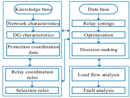
Expert system based protection coordination—expert system is a software inspired by the human behavior of solving issues or making rational decisions. Expert systems are used where the traditional data processing is not feasible. Operating on their knowledge database and expertise the expert systems, as a result, also give the reasons on the solution choice [88,89]. Expert systems are used in industrial networks for relay coordination after DG integration. Multiple relay settings were evolved for 22kV distribution network using expert systems [90], on the basis of load flow, and fault analysis. The general scheme diagram for expert system based protection coordination is shown in Figure 1[90].
The utilization of expert systems for coordination of the protection devices (i.e., relays, fuses and reclosers) in a 33 kV radial system for small scale DGs is suggested in [91]. Protection Device Coordination Expert System (PDCES) software is developed in [92] to help the utility operator evaluate the protection coordination issues. PDCES assesses the causes of mis-coordination, proposes solutions, and ranks the remedies, so that an appropriate action can be taken in accordance to the network characteristics. The potential usage of expert system in protection coordination studies is proposed in [93,94].
Knowledge base
Network characteristics Relay settings
Data base
DG characteristics Optimization
Protection coordination
data Decision making
Relay coordination
rules Load flow analysis
Selection rules Fault analysis
Figure 1. Expert System based protection coordination scheme.
Adaptive protection coordination—an emerging technique in power systems with low DGs penetration. It has ability to automatically process the data when conditions of the network changes with integration of DG. The defined rules and algorithms take the necessary actions accordingly, to achieve the high level of protection coordination in all the abnormal scenarios [95]. The adaptive technique used in [96], checks the relay settings after connection of every new DG on the basis of short circuit currents flowing through the protective devices. Adaptive scheme used in [97], evolves the coordination between protective devices on the basis of coordination time interval margin between their curves. An adaptive scheme suggested in [98] maintains coordination between the fuses in distribution network but all the DGs get disconnected at the instant of fault.
Storing system configuration using LINKNET structure
Optimal protection coordination of realys Yes
No Determining settings of relays using
LINKNET vector
Determining number, rating & place of DGs in system & DG counter_initial
value of FCL
Execute power flow & fault analyses
New sets of relay settings after DGs integration
Install FCL & execute short circuit analysis for all fault places
(CTI)i,j < preset (CTI)
(CTI)i,j > = preset (CTI)
Retrieve least value of FCL
New set of DGs = old set of DGs + 1
Considering all DGs After DG
placement placementAfter DG
No Yes
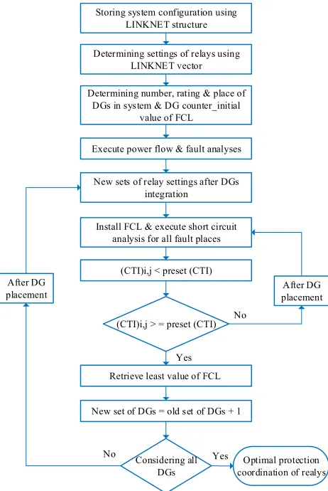
Figure 2. FCL based protection coordination.
One way to overcome the issue of mis-coordination between protection devices after DG integration might be a replacement of the existing scheme for a new one with higher rating, but this would be a costly option. Another way is to limit the value of fault current to the acceptable level so that the existing schemes may operate effectively [100]. The fault current limiters are connected in series with distribution lines to limit the amount of fault current contributions from the DGs. However, fault limiters cause small amount of loading and contribute to the power losses during normal conditions [101]. The LINKNET is type of data structure used to determine the set of random variables.
Directional overcurrent protection coordination—the directional element is added to the conventional overcurrent relays to deal with the bidirectional power flows caused by integration of DGs. This ideas used in [102–104] to isolate internal and external faults in the microgrid. The scheme of operation is based on directional overcurrent relays with additional communication and is relatively expensive. The directional protection scheme with master-slave concept is suggested in [105] to protect the micro-grid system against the external and internal faults. The proposed scheme has communication ability to detect the direction and location of fault. The directional protection scheme using microprocessor based relays proposed in [106] is used to protect the connected grid and also islanded DGs. This proposed scheme does not require communication link and is independent on the level of fault current values and the operation mode of DGs. The limitations of directional overcurrent protection have been identified in [107]. It is pointed out that the unintentional and frequent connection and disconnection of DGs affects the network configuration and the settings of protection devices.
5 of 24
fault current and load currents so the overcurrent relays are able to distinguish between faulty and normal conditions. However, after the installation of DGs, the margin between the load current and fault current is small and thus the relays cannot efficiently discriminate between them [108]. A method based on voltage-current inverse characteristics is proposed in [109–111] to discriminate between the faulty and normal conditions.
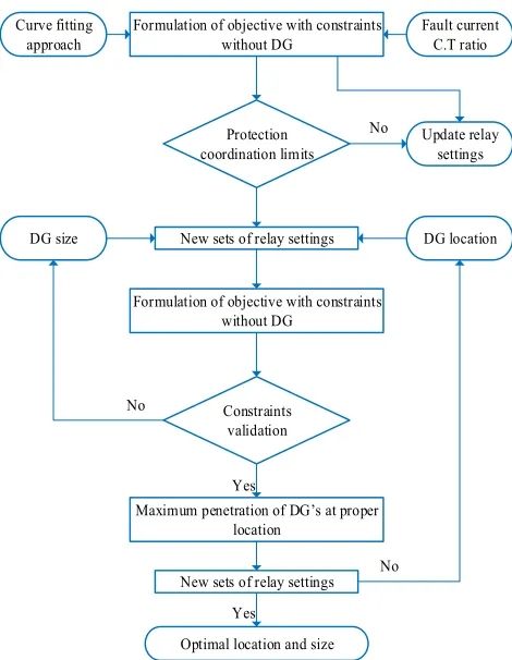
Selection of DGs location and size—the location and size of DG have significant importance in the protection coordination study. The optimal sizing and placement of DG would cause small disturbances in coordination schemes of distribution network. The general scheme of such a method is shown in Figure 3.
Curve fitting approach
Formulation of objective with constraints without DG
New sets of relay settings
Optimal location and size Yes
No
Fault current C.T ratio
Protection coordination limits
Update relay settings
DG location DG size
Formulation of objective with constraints without DG
Constraints validation
No
Maximum penetration of DG’s at proper location
No New sets of relay settings
Yes
Figure 3. DGs location and sizing based relaying scheme.
The protection coordination scheme discussed in [112] evaluated the effect of size and location of DG on the overcurrent network protection based on fault current in upstream and downstream networks. In [113] the limitations for DGs’ penetration are suggested to maintain coordination between conventional protection devices. The effect of size and location of DG on the coordination time interval (CTI) margin of inverse time overcurrent relays is analyzed in [114]. The sensitivity of relays in upstream and downstream network at different DGs location and size is also discussed.
Multi-agent protection coordination—a method gaining popularity in protection coordination studies. An agent is an intelligent system which performs the defined autonomous functions in order to achieve desired objectives. The task performed by agents exist in predefined environment and their infrastructure contains communication and interface links [120]. The general scheme of multi-agent protection coordination is shown in Figure 4 [121]. An efficient protection coordination scheme using multi-agents for distribution networks with DGs connected is proposed in [122–124]. A multi-agent based protection coordination scheme proposed in [125] coordinates the overcurrent relays via communication link to enhance the efficiency of protection coordination and to decrease the operating time of relays. The multi-agent protection scheme proposed in [126] divides the system into various protection zones. This protection scheme has distributed control but makes coordinated decisions. Then, a peer-to-peer multi-agent protection coordination is suggested in [127]. A multi-agent approach is also used in cases where the operational timing of relays is longer due to small fault currents in the network. The inverter based DGs connected to low voltage network contribute small amount of current to the fault points [128,129]. Also, a communication based protection coordination scheme using synchro-phasors is used in [130].
Control and decision making agents
Monitoring agent Network configuration agent Protection coordination agent Protection agent Measuring agent
Control and decision making agents
Figure 4. Multi-agent relaying scheme.
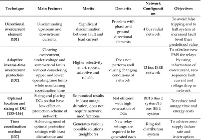
Table 4. Summary of Methods for Protection Coordination of DGs.
Technique Main Features Merits Demerits
Network Configurati
on Objectives
Directional overcurrent element [131] Discriminating upstream and downstream currents. Significant discrimination between fault and
load current Problem with phase and ground directional elements
4 bus radial network
To avoid false tripping and to
halt system at increased fault level than predefined value Adaptive inverse-time overcurrent protection [132] Clearing overcurrent, under-voltage and symmetrical faults without considering
upper and lower operating time limits
while maintaining coordination time Higher selectivity, smart, robust, adaptive and reliable Does not perform well during changing conditions of network
13 bus IEEE network
To calculate new PMS for relays
by using information of overcurrent, zero
sequence fault current and voltage drop in
network Optimal
location and sizing of DG [133–136]
Sizing and placing DGs so that have
low effect on protection scheme of
network
Economical results in least outage duration, does not
require network modifications Not efficient with high penetration of DGs
RBTS Bus 2 system/15
bus IEEE system
To reduce total outage time and
energy costs
Time coordination
method [137]
Achieving most of optimal protection settings with least disturbance and Generates various possible solutions (neighbors) New relay settings are required to be generated each
Ring-fed distribution
system
To achieve zero supply failure
7 of 24
failure timings time with new
DGs frequency
Solid state unidirectional fault current limiter (SSUFCL) [138] Restricting fault currents within defined zones used
as an interface between upstream
and downstream networks.
Suitable for DGs with storage system and converter technology Unable to provide discrimination between upstream and downstream relays close to
DGs
7 bus test system
To optimize the time and current
settings of overcurrent relays and characteristics of SSUFCL Adaptive differential current protection [139]
Changing values of fault level and
network configuration are required for relay coordination in both
grid-connected and islanded mode DGs
Applicable to MV network with inverter based DG
technology
Cannot be applied to synchronous
DGs
3 bus radial network
To avoid false fault detection based on differential current with least frequency deviations between supply and load Multi-agent adaptive protection coordination [140,141]
Deciding settings of digital overcurrent relays on the basis of
condition of agents and communication
between them
Used for complex networks with frequent changing dynamics Continuous communication between overcurrent relay agents, feeder agents and display agents are required
2 bus radial network/4 bus radial network To determine relays settings through learning algorithm and communicate with its neighboring agents Directional protection with fault current limiter (FCL) [142] Determining settings of FCL through algorithm that limits
the fault current
Eliminates complexity in control strategies, ensures reliability and safety of network at the
lowest costs
Connection and disconnection of DGs may affect
the values of FCL and relay
settings
30 bus IEEE system
To minimize the cost function at
zero values of FCLs Voltage sag coordination technique [143,144] Disconnecting DG from the system when voltage falls below 0.5 p.u in less
than six cycles and coordinating relays on the basis of specific energy as the function of time.
Can be applied to both synchronous and static DGs
with different ratings
More laborious, limited to small
DGs
1 bus radial network To maintain standard coordination time margin Adaptive protection coordination [145]
Calculating time dial and plug multiplier settings of relays on the basis of varying parameters/configur ation of the network
Extremely flexible to maintain the
coordination among overcurrent relays and distance relays Communication and numerical relays are required for obtaining best settings
8 bus test system and14 bus IEEE network To avoid nuisance tripping of overcurrent and distance relays at
distribution and transmission levels respectively Directional inverse time overcurrent protection [146] Estimating the direction of fault current on the basis
of its angle with polarizing voltage in
both forward and reverse directions for relay settings
Used for complex power networks
and for systems with changing
dynamics
Additional nonlinear multi-variable function is used
which only works for continuous first
derivatives of the system
30 bus IEEE network
To diminish the coordination delay between relays while maintaining protection coordination limits Centralized adaptive scheme
Optimizing the relay setting on the basis
of network
Automatic online coordination, desired selectivity
For every change in the
network
6 bus interconnect
ed network
To minimize the primary and
[147] conditions, using SCADA server that
retrieves the network data and perform load flow, contingency analysis
and sensitivity analysis.
and sensitivity conditions, the process is
repeated
operation time of relays while retaining desired selectivity Neuro-fuzzy protection [148] Deciding the optimal settings of IDMT relays based on the status of DG
and network conditions. With Fuzzy inference The
results are optimized through neural network with
voltage and current phasor based DFT
algorithm Applicable to networks with changing parameters and with multiple DGs’ integration. Better performance in terms of speed and
efficiency
Complexity is high, computational times are large
34 bus IEEE system
To ensure desired coordination time in closed
loop system
Expert System protection coordination
[90,149]
Using expert system as decision tool to investigate the effect
of DG integration and proposes
protection coordination settings for relays
Simple, robust and suitable for system
with multiple coordination settings With changing configuration of network, computation processing time is large 22-kV test system
To identify the maximum and minimum fault currents in the protection zones Communicati on assisted digital relay scheme [150] Providing under-voltage and overcurrent protection with grouped relays based on short circuit capacity of
system
Used for high impedance faults and integration of multiple DGs Complete knowledge of entire configuration and parameters
of network is difficult and
security of communication link is necessary.
6 busand 13 bus loop network
To optimize location and number of relays
according to network configuration and characteristics of DGs Coordinated backup protection [151] Analyzing different faults based on
coordinated substation which works on differential principle and acts as backup for master
station
Suitable for network with varying power flows, does not require complete information about system Communication protocol between master station and coordinated station is required to be
secure
14 bus IEEE system
To minimize the probability of
protection failure
4. Future Scope and Recommendations
In this article, authors have identified the possible future scope and challenges for protection coordination schemes and DG location and sizing methods.
4.1. DG Location and Sizing Methods
(1) The optimal sizing and placement of DGs, proper placement of capacitor banks and the network reconfiguration are the three best options for minimizing the power losses in distribution systems. The coordination planning of all these three options results in economical results. Therefore, during the network reconfiguration, proper placement and sizing of DGs, capacitor banks and protection devices should be carried out simultaneously.
9 of 24
(3) The optimizations methods used for optimal sizing and location of DGs are based on trial and error methods. In order to improve their performance and efficacy, their objective functions should be evaluated adaptively and automatically.
(4) The stability of distribution system should be considered after large penetrations of DGs because the system becomes active then. Moreover, the energy management strategy during transient operation of network should be designed with available distributed generation. (5) The effects of new DG installation on the characteristics of existing DGs in distribution
network should be analyzed. The dynamic model for proper placement and sizing of DGs will be an effective solution.
(6) With the installation of DGs, not only voltage of network is rised up but also the power quality is significantly being changed. With the online monitoring and control of distribution network, the capacity of network to accommodate new DGs can be determined, the new relay settings can be deduced and the cost of integrating DGs can be calculated. The Online Management System (OMS) integrated with model of DGs placement and sizing is the work of future research.
(7) The different parameters of objective functions of DGs placement and sizing algorithms are uncertain such as; output power of distributed sources, future power demand, fuel costs, market trends, charging and discharging characteristics of electric vehicles, future investments, availability of fuel reserves, etc. Therefore, deterministic and evolutionary algorithms should be used to deal with such uncertainties.
4.2. Schemes of Protection Coordination
(1) High penetration of DGs at distribution levels affects the reach of upstream distance relays at transmission level. Therefore, during installation of multiple DGs, not only relays settings of downstream distribution system but also relays at upstream transmission level should be considered.
(2) Since the relays are coordinated while considering the lower limit of CTI and neglecting its upper limit. Thus, in case of low fault current contributions from DGs, the operation of backup overcurrent protection is delayed. Therefore, in order to achieve optimal operation of overcurrent relays during such scenarios, time inverse current relay characteristics should be applied in relay coordination schemes.
(3) Installation of DGs influences the configuration of distribution network and hence directional relays are installed to distinguish between the upstream and downstream fault currents. In such situations, the selection of relays settings for backup protection becomes more complicated and thus simple curve fitting techniques are ineffective to do so. Therefore, modern communication based techniques are required to solve such issue for highly complex systems.
(4) Integration of photo-voltaic systems into power system makes the protection schemes more complicated due to their small fault current contribution. Under such conditions, the accuracy and robustness of protection schemes is a challenging task. Using voltage sag characteristics of system, protection schemes for distribution with PV system can be designed.
(5) With high penetration of DGs, the communication based coordination schemes with distributed adaptive techniques become inactive. In future coordination studies, this issue should be considered.
(6) In [142], Author used the information of voltage sag for protection coordination of relays and in [145], Author coordinated the relays using fault current angle. Since, with high penetration of DGs into distribution network, not only the magnitude of voltage is affected but also its angle, during the steady state as well as during the transient conditions. Therefore, a new protection scheme can be designed on the basis of both parameters of voltage sag (magnitude+angle), which is ongoing research of Authors
Such issue should be considered while integrating DGs into distribution network during steady state and dynamic conditions of system.
5. Conclusions
This article presented the detailed review of protection coordination schemes and placement and sizing methods of DGs in distribution networks. The integration of DG into distribution system creates many protection coordination issues. The sensitivity of these issues highly depends upon the place and rating of incoming DG. Therefore, different methods and optimization techniques for optimal placement and sizing of DG were discussed. The most common objective among all the techniques was the reduction of losses and enhancement of voltage profile. The most frequently used methods for proper placement and sizing of DG are Genetic Algorithm (GA) and different practical heuristic algorithms.
After the DGs are optimally sized and placed then issues arise with bidirectional power flows in distribution networks. The existing protection schemes fail to clear the faults correctly. This article addressed various protection coordination methods. The application of different protection schemes were based on the characteristics of network and installed DGs. The protection coordination problems were formulated as linear and non-linear problems and were then evolved by different optimization methods to determine their optimal protection settings. All the discussed protection schemes were based on restraining the adverse effects of DGs and updating their protection characteristics.
This article also discussed possible research gaps, applications and limitations of different protection coordination schemes and DG sizing and placement methods.
Author Contributions: L.S. was responsible for conceptualization and methodology, S.K. performed analysis, research and original draft preparation, Z.L. performed supervision, review and editing.
Funding: This research was partially funded by Wroclaw University of Science and Technology, grant number 0401/0037/17.
Acknowledgments: Authors are very much thankful to Wroclaw University of Science and Technology, Poland for providing peaceful and stimulating environment for conducting this research work. The first author is very much grateful to Nisar Ahmed Siddiqui, Vice Chancellor of Sukkur IBA University for always motivating and appreciating the research work conducted.
Conflicts of Interest: The authors declare no conflict of interest. References
1. Howell, S.; Rezgui, Y.; Hippolyte, J.L.; Jayan, B.; Li, H. Towards the next generation of smart grids: Semantic and holonic multi-agent management of distributed energy resources. Renew. Sustain. EnergyRev. 2017, 77, 193–214.
2. Balamurugan, K.; Srinivasan, D.; Reindl, T. Impact of Distributed Generation on Power Distribution Systems. EnergyProcedia2012, 25, 93–100.
3. Juan, Y.; Ming, S.; Bo, D. Research about Impact of DGs in Distribution Network. IEEE Ind. Appl. Mag.2003, 1–6.
4. Ogunjuyigbe, A.S.O.; Ayodele, T.R.; Akinola, O.O. Impact of distributed generators on the power loss and voltage profile of subtransmission network. J. Electr. Syst. Inf. Technol.2015, 3, 94–107.
5. Hlatshwayo, M.; Chowdhury, S.; Chowdhury, S.P.; Awodele, K.O. Impacts of DO Penetration in the Reliability of Distribution Systems. In Proceedings of the International Conference on Power System Technology, Hangzhou, China, 24–28 October2010.
6. Muhammad Yousaf, Tahir Mahmood, "Protection coordination for a distribution system in the presence of distributed generation", Turkish Journal of Electrical Engineering & Computer Sciences, 2017, 25, 408-421. 7. Sharaf, H.M.; Zeineldin, H.H.; Ibrahim, D.K.; Zahab, E. A proposed coordination strategy for meshed
11 of 24
8. Haron, A.R.; Mohamed, A.; Shareef, H. Coordination of Overcurrent Directional and Differential Relays for the Protection of Microgrid System. Procedia Technol. 2013, 11, 366–373.
9. Georgilakis, P.S.; Hatziargyriou, N.D. Optimal distributed generation placement in power distribution networks: Models methods and future research. IEEE Trans. Power Syst. 2013, 28, 3420–3428.
10. Shanna, P.; Tandon, A. Techniques for Optimal Placement of DG in Radial Distribution System: A Review. In Proceeding of the International Conference on Communication, Control and Intelligent Systems, Mathura, India, 7–8 November2015.
11. El-Khattam, W.; Salama, M. Distributed generation technologies definitions and benefits. Electr. Power Syst. Res. 2004, 71, 119–128.
12. Rau, N.S.; Wan, Y.-H. Optimum location of resources in distributed planning. IEEETrans. PowerSyst. 1994, 9, 2014–2020.
13. Vovos, P.; Bialek, J. Direct incorporation of fault level constraints in optimal power flow as a tool for network capacity analysis. IEEETrans. PowerSyst. 2005, 20, 2125–2134.
14. Keane, A.; O’Malley, M. Optimal allocation of embedded generation on distribution networks. IEEETrans. PowerSyst. 2005, 20, 1640–1646.
15. Keane, A.; O’Malley, M. Optimal utilization of distribution networks for energy harvesting. IEEETrans. PowerSyst. 2007, 22, 467–475.
16. Vovos, P.N.; Harrison, G.P.; Wallace, A.R.; Bialek, J.W. Optimal power flow as a tool for fault level-constrained network capacity analysis. IEEETrans. PowerSyst. 2005, 20, 734–741.
17. AlHajri, M.F.; AlRashidi, M.R.; El-Hawary, M.E. Improved sequential quadratic programming approach for optimal distribution generation deployments via stability and sensitivity analyses. Electr. PowerCompon. Syst. 2010, 38, 1595–1614.
18. M. F. AlHajri, M. R. AlRashidi, and M. E. El-Hawary, Improved Sequential Quadratic Programming approach for optimal Distribution Generation sizing in distribution networks, Proceedings of the 23rd Canadian Conference on Electrical and Computer Engineering, 2010, doi: 10.1109/CCECE.2010.5575191 19. Zhu, D.; Broadwater, R.P.; Tam, K.-S.; Seguin, R.; Asgeirsson, H. Impact of DG placement on reliability
and efficiency with time-varying loads. IEEETrans. PowerSyst. 2006, 21, 419–427.
20. Mahmoud Pesaran H. A., Abdullah Asuhaimi Bin Mohd Zin, Azhar Bin Khairuddin & Omid Shariati, “Optimal Sizing and Siting of Distributed Generators by Exhaustive Search”, Distributed Generation & Alternative Energy Journal, 2015, 30:3, 29-56, DOI: 10.1080/21563306.2015.11461421
21. M. Abdel-Akher, A. A. Ali, A. M. Eid, H. El-Kishky, "Optimal size and location of distributed generation unit for voltage stability enhancement", Proc. IEEE ECCE,2011, pp. 104-108, doi: 10.1109/ECCE.2011.6063755
22. Khan, H.; Choudhry, M.A. Implementation of distributed generation (IDG) algorithm for performance enhancement of distribution feeder under extreme load growth. Int. J. Electr. PowerEnergySyst. 2010, 32, 985–997.
23. Ochoa, L.F.; Padilha-Feltrin, A.; Harrison, G.P. Evaluating distributed time-varying generation through a multiobjective index. IEEETrans. PowerDeliv. 2008, 23, 1132–1138.
24. Jabr, R.A.; Pal, B.C. Ordinal optimisation approach for locating and sizing of distributed generation. IETGener. Transm. Distrib. 2009, 3, 713–723.
25. Khalesi, N.; Rezaei, N.; Haghifam, M.-R. DG allocation with application of dynamic programming for loss reduction and reliability improvement. Int. J. Electr. PowerEnergySyst. 2010, 33, 288–295.
26. Ochoa, L.F.; Dent, C.J.; Harrison, G.P. Distribution network capacity assessment: Variable DG and active networks. IEEETrans. PowerSyst. 2010, 25, 87–95.
27. Dent, C.J.; Ochoa, L.F.; Harrison, G.P. Network distributed generation capacity analysis using OPF with voltage step constraints. IEEETrans. PowerSyst. 2010, 25, 296–304.
28. Ochoa, L.F.; Harrison, G.P. Minimizing energy losses: Optimal accommodation and smart operation of renewable distributed generation. IEEETrans. PowerSyst. 2011, 26, 198–205.
29. Atwa, Y.M.; El-Saadany, E.F. Probabilistic approach for optimal allocation of wind-based distributed generation in distribution systems. IETRenew. PowerGener. 2011, 5, 79–88.
31. Al Abri, R.S.; El-Saadany, E.F.; Atwa, Y.M. Optimal placement and sizing method to improve the voltage stability margin in a distribution system using distributed generation. IEEE Trans. Power Syst. 2013, 28, 326–334.
32. Kumar, A.; Gao, W. Optimal distributed generation location using mixed integer non-linear programming in hybrid electricity markets. IETGener. Transm. Distrib. 2010, 4, 281–298.
33. Porkar, S.; Poure, P.; Abbaspour-Tehrani-Fard, A.; Saadate, S. Optimal allocation of distributed generation using a two-stage multi-objective mixed-integer-nonlinear programming. Eur. Trans. Electr. Power2011, 21, 1072–1087.
34. El-Khattam, W.; Hegazy, Y.G.; Salama, M.M.A. An integrated distributed generation optimization model for distribution system planning. IEEETrans. PowerSyst. 2005, 20, 1158–1165.
35. Singh, D.; Mirsa, R.K.; Singh, D. Effect of Load Models in Distributed Generation Planning. IEEETrans. PowerSyst. 2007, 22, 2204–2212.
36. Zeineldin, H.H.; Mohamed, Y.; Khadkikar, V.; Pandi, V.R.A protection coordination index for evaluating distributed generation impacts on protection for meshed distribution systems. IEEE Trans. Smart Grid 2013, 4, 1523–1532.
37. Kotamarty, S.; Khushalani, S.; Schulz, N. Impact of Distributed Generation on Distribution Contingency Analysis. Electr. Power Syst. Res. 2008, 78, 1537–1545.
38. Saleh KAZeineldinHHEl-Saadany, E.F. Optimal protection coordination for microgrids considering N-1 contingency. IEEE Trans. Ind. Inf. 2017, 13, 2270–2278.
39. Willis, H.L. Analytical methods and rules of thumb for modeling DG-distribution interaction. In Proceedings of the IEEE Power Engineering Society Summer Meeting, Seattle, WA, USA, 16–20July 2000; pp. 1643–1644.
40. Lee, S.-H.; Park, J.-W. Selection of optimal location and size of multiple distributed generations by using Kalman filter algorithm. IEEETrans. PowerSyst. 2009, 24, 1393–1400.
41. Gözel, T.; Hocaoglu, M.H. An analytical method for the sizing and siting of distributed generators in radial systems. Electr. Power Syst. Res. 2009, 79, 912–918.
42. Hung, D.Q.; Mithulananthan, N.; Bansal, R.C. Analytical Expres-sions for DG Allocation in Primary Distribution Networks. IEEETrans. EnergyConvers. 2010, 25, 814–820.
43. Hung, D.Q.; Mithulananthan, N. Multiple Distributed Generators Placement in Primary Distribution Networks for Loss Reduction. IEEETrans. Ind. Electron. 2013, 60, 1700–1708.
44. Acharya, N.; Mahat, P.; Mithulananthan, N. An analytical Approach for DG Allocation in Primary Distribution Network. J.Electr. PowerEnergySyst. 2006, 28, 669–678.
45. Costa, P.M.; Matos, M.A. Avoided Losses on LV Networksas a Result of Microgeneration. Electr. Power Syst. Res. 2009, 79, 629–634.
46. Man, K.F.; Tang, K.S.; Kwong, S. Genetic algorithms: Concepts and applications. IEEETrans. Ind. Electron. 1996, 43, 519–534.
47. Borges, C.L.T.; Falcão, D.M. Optimal distributed generation allocation for reliability, losses, and voltage improvement. Int. J.Electr. Power Energy Syst. 2006, 28, 413–420.
48. Singh, R.K.; Goswami, S.K. Optimum siting and sizing of distributed generations in radial and networked systems. Electr. PowerCompon. Syst. 2009, 37, 127–145.
49. Singh, D.; Singh, D.; Verma, K.-S. Multiobjective optimization for DG planning with load models. IEEETrans. PowerSyst. 2009, 24, 427–436.
50. Singh, R.K.; Goswami, S.K. Optimum allocation of distributed generations based on nodal pricing for profit, loss reduction, and voltage improvement including voltage rise issue. Int. J. Electr. PowerEnergySyst. 2010, 32, 637–644.
51. Caprinelli, G.; Celli, G.; Pilo, F.; Russo, A. Embedded generation planning under uncertainty including power quality issues. Eur. Trans. Electr. Power2003, 13, 381–389.
52. Kim, K.-H.; Lee, Y.-J.; Rhee, S.-B.; Lee, S.-K.; You, S.-K. Dispersed generator placement using fuzzy-GA in distribution systems. In Proceedings of the IEEE Power Engineering Society Summer Meeting, Chicago, IL, USA, 25July 2002; pp. 1148–1153.
53. Akorede, M.F.; Hizam, H.; Aris, I.; Kadir, M.Z.A.A. Effective method for optimal allocation of distributed generation units in meshed electric power systems. IETGener. Transm. Distrib. 2011, 5, 276–287.
13 of 24
55. Kim, K.-H.; Song, K.-B.; Joo, S.-K.; Lee, Y.-J.; Kim, J.-O. Multiobjective distributed generation placement using fuzzy goal programming with genetic algorithm. Eur. Trans. Electr. Power2008, 18, 217–230. 56. Teng, J.-H.; Liu, Y.-H.; Chen, C.-Y.; Chen, C.-F. Value-based distributed generator placements for service
quality improvements. Int. J.Electr. Power Energy Syst. 2007, 29, 268–274.
57. Prasanna, H.A.M.; Kumar, M.V.L.; Ananthpadmnabh, T. A Novel Approach for Optimal Allocation of a Distributed Generation in a Radial Distribution Feeder for Loss Minimization and Tail End Node Voltage Improvement during Peak Load; IJECES 2, No. I; Science and Education Publishing: New York, NY, USA, 2014; pp. 67–72.
58. Song, M.-P.; Gu, G.-C. Research on Particle Swarm Optimization: A Review. In Proceedings of the Third International Conference on Machine Learning and Cybernetics, Shanghai, China, 26–29 August2004, pp. 2216–2241.
59. Prommee, W.; Ongsakul, W. Optimal multiple distributed generation placement in microgrid system by improved reinitialized socialstructures particle swarm optimization. Eur. Trans. Electr. Power2011, 21, 489–504.
60. El-Zonkoly, A.M. Optimal placement of multi-distributed generation units including different load models using particle swarm optimisation. IETGener. Transm. Distrib. 2011, 5, 760–771.
61. Pandi, V.R.; Zeineldin, H.H.; Xiao, W. Determining optimal location and size of distributed generation resources considering harmonic and protection coordination limits. IEEE Trans. Power Syst. 2013, 28, 1245–1254.
62. Nayyar, A.; Singh, R. Ant Colony Optimization- Computational Swarm Intelligence Technique. In Proceedings of the International Conference on Computing for Sustainable Global Development, New Delhi, India, 16–18 March2016; pp. 1493–1499.
63. Wang, L.; Singh, C. Reliability-constrained optimum placement of reclosers and distributed generators in distribution networks using an ant colony system algorithm. IEEETrans. Syst.Man Cybern. CAppl. Rev. 2008, 38, 757–764.
64. Bi, X.; Wang, Y. An improved artificial bee colony algorithm. In Proceedings of the 3rd International Conference on Computer Research and Development (ICCRD), Shanghai, China, 11–13 March2011; pp. 174–177.
65. Abu-mouti, F.S.; El-Hawary, M.E. Heuristic Curve Fitted Technique for Distributed Generation Optimization in Radial Distribution Feeder System. LETGener. Transm. Distrib. 2009, 5, 172–180.
66. Suganthan, P.N. Differential evolution algorithm: Recent advances. In TPNC 2012. LNCS 7505; Dediu, A.-H., Martín-Vide, C., Truthe, B., Eds.; Springer: Heidelberg, Germany, 2012; pp. 30–46.
67. Arya, L.D.; Koshti, A.; Choube, S.C. Distributed generation planning using differential evolution accounting voltage stability consideration. Int. J. Electr. PowerEnergySyst. 2012, 42, 196–207.
68. Ammar, M.; Bouaziz, S.; Alimi, A.M.; Abraham, A. Hybrid Harmony Search algorithm for Global Optimization. In Proceedings of the Fifth World Congress on Nature and Biologically Inspired Computing, Fargo, ND, USA, 12–14 August 2013; pp. 69–75.
69. Rao, R.; Ravindra, K.; Satish, K.; Narasimham, S. Power loss minimization in distribution system using network reconfiguration in the presence of distributed generation. IEEE Trans. Power Syst. 2013, 28, 317–325.
70. Glover, F. Tabu search—Part I. ORSA J. Comput. 1989, 1, 190–206.
71. Nara, K.; Hayashi, Y.; Ikeda, K.; Ashizawa, T. Application of tabu search to optimal placement of distributed generators. In Proceedings of the IEEE Power Engineering Society Winter Meeting, New York, NY, USA, 28 January–1 February 2001; pp. 918–923.
72. Golshan, M.E.H.; Arefifar, S.A. Optimal allocation of distributed generation and reactive sources considering tap positions of voltage regulators as control variables. Eur. Trans. Electr. Power2007, 17, 219–239.
73. Abdelaziz, A.Y.; Hegazy, Y.G.; Mahmoud, W.E.M. Othman: A multi objective optimization for sizing and placement of voltage controlled distributed generation using supervised big bang-big crunch method. Electr. PowerCompon.Syst. 2015, 43, 105–117.
75. El-Khattam, W.; Bhattacharya, K.; Hegazy, Y.; Salama, M.M.A. Optimal investment planning for distributed generation in a competitive electricity market. IEEETrans. PowerSyst. 2004, 19, 1674–1684. 76. Hamedi, H.; Gandomkar, M. A straightforward approach to minimizing unsupplied energy and power
loss through DG placement and evaluating power quality in relation to load variations over time. Int. J. Electr. PowerEnergySyst. 2012, 35, 93–96.
77. Banerjee, B.; Islam, S.M. Reliability based optimum location of distributed generation. Int. J. Electr. PowerEnergySyst. 2011, 33, 1470–1478.
78. Ghosh, S.; Ghoshal, S.P.; Ghosh, S. Optimal sizing and placement of distributed generation in a network system. Int. J. Electr. PowerEnergySyst. 2010, 32, 849–856.
79. Cavazos, J.; Moss, J.E.B.; O’Boyle, M.F. Hybrid optimizations: Which optimization algorithm to use? In Proceedings of the International Conference on Compiler Construction (ETAPS CC’06), Vienna, Austria, 30–31March 2006; Springer-Verlag: Vienna, Austria, 2006; pp. 185–201.
80. Kefayat, M.; Ara, A.L.; Niaki, S.N. A hybrid of ant colony optimization and artificial bee colony algorithm for probabilistic optimal placement and sizing of distributed energy resources. Energy Convers. Manag. 2015, 92, 149–161.
81. Gandomkar, M.; Vakilian, M.; Ehsan, M. A genetic-based tabu search algorithm for optimal DG allocation in distribution networks. Electr. PowerCompon. Syst. 2005, 33, 1351–1362.
82. Moradi, M.H.; Abedini, M. A combination of genetic algorithm and particle swarm optimization for optimal DG location and sizing in distribution systems. Int. J. Electr. PowerEnergySyst. 2012, 34, 66–74. 83. Sadeh, T.J.; Bashir, M.; Kamyab, E. Effect of distributed generation capacity on the coordination of
protection system of distribution network. Proc. IEEE2010, doi: 110–115. 10.1109/TDC-LA.2010.5762869 84. Kennedy, J.; Ciufo, P.; Agalgaonkar, A. A review of protection systems for distribution networks
embedded with renewable generation. Renew. Sustain. Energy Rev. 2016, 58, 1308–1317.
85. Singh, M. Protection coordination in distribution systems with and without distributed energy resources—A review. Prot. Control. Mod. PowerSyst. 2017, 2, 1–17.
86. Etemadi, A.H.; Fotuhi-Firuzabad, M. New considerations in modern protection system quantitative reliability assessment. IEEETrans. PowerDeliv. 2010, 24, 2213–2222.
87. Nimpitiwan, N.; Heydt, G.T.; Ayyanar, R.; Suryanarayanan, S. Fault current contribution from synchronous machine and inverter based distributed generators. IEEETrans. PowerDeliv. 2007, 22, 634–641. 88. Liao, S.-H. Expert system methodologies and applications: A decade review from 1995 to 2004. Expert Syst.
Appl. 2005, 28, 93–103.
89. Park, D.H.; Kim, H.K.; Choi, I.Y.; Kim, J.K. A literature review and classification of recommender systems research. ExpertSyst.Appl.2012, 39, 10059–10072.
90. Tuitemwong, K.; Premrudeepreechacharn, S. Expert system for protection coordination of distribution system with distributed generators. Int. J.Electr. Power Energy Syst. 2011, 33, 466–471.
91. R.P. Broadwater, J.C. Thompson, S. Rahman, A. Sargent, "An expert system for integrated protection design with configurable distribution circuits. II", IEEE Transactions on Power Delivery, vol. 9, no. 2, pp. 1121-1128, April 1994.
92. Tuitemwong, K.; Premrudeepreechacharn, S. Expert System for Protective Devices Coordination in Radial Distribution Network with Small Power Producers. Knowl. Creation Diffus. Util.2007, 1159–1164, doi: 10.1109/PCT.2007.4538479
93. Lai, L.L. Development of an Expert System for Power System Protection Coordination. In Proceedings of the Fourth International Conference in Power System Protection, Edinburgh, UK, 11–13 April 1989; pp. 310–314.
94. L. L. Lai, An expert system used in power system protection. In Proceedings of the IFAC International Symposium, Seoul, Korea, 22–25 August 1989.
95. J. C. Tan, P. A. Crossley, D. Kirschen, J. Goody, J. A. Downes, "An expert system for the back-up protection of a transmission network", IEEE Transactions on Power Delivery, vol. 15, no. 2, pp. 508-514, April 2000. 96. Singh, M.; Vishnuvardhan, T.; Srivani, S.G. Adaptive protection coordination scheme for power networks
under penetration of distributed energy resources. IET Gener. Transm. Distrib. 2016, 10, 3919–3929. 97. Girgis, A.; Brahma, S. Effect of distributed generation on protective device coordination in distribution