The physics of electric power systems
C. Ohler
ABB Switzerland, Corporate Research - CH-5405 Baden-D¨attwil, Switzerland
Summary.— The article describes electric power systems from a physicist’s point of view. In contrast to common introductory textbooks on power systems, the em-phasis is on the physical design, that is the material selection and the choice of the geometrical shape, of the fundamental components as it follows from the function and serves the main purpose. Why do power system components look the way they look? This is the question addressed in an accessible way. Four fundamental com-ponents are needed to make the most elementary power system: overhead transmis-sion lines, transformers, synchronous generators, and circuit breakers. High-voltage overhead lines make efficient long-distance transmission of electric power possible. Transformers step up the power from the generating plant and cascade it down to the final consumption. For their ability to control, independently, real and reactive power, synchronous generators are the most common type of generators. And it is only through the immediate extinction of plasma arcs in circuit breakers that short-circuit currents can be interrupted and faulty segments of the grid disconnected.
1. – Introduction
Fig. 1. – Overhead transmission line and details of the steel reinforced aluminium conductor and a suspension insulator.
Electricity is supplied through large power grids because this brings the lowest cost and provides the highest reliability. As the power grid extends over many consumers, individual decisions to switch on or switch off lights average out, so that the bulk of elec-tricity can be supplied by central cost-efficient power plants either running continuouosly in base load operation or scheduled according to the general day-night pattern of human activity. The unexpected failure of a single power plant is a marginal statistical event, so that the number of power plants that idle for being ready to jump in for backup supply is less than 1% of the installed power. Power grids are extremely reliable, the weighted average interruption duration per consumer is 15 to 60 minutes per year (0.005% of the time) in Europe and the United States [1].
The purpose of this lecture is to provide a comprehensible introduction into the physics of power systems. This is done by describing the design — geometrical shape and se-lection of materials — as it follows from the function of the four main power system components. The four elementary components of power systems are the overhead trans-mission lines, transformers, synchronous generators, and circuit breakers. For a recent introductory textbook from the electrical engineer’s perspective, see ref. [2].
2. – Overhead transmission lines
The most visible components of power systems are the overhead transmission lines as shown in fig. 1. A curious observer with fresh eyes would notice at least four things. First, there is the mere fact that it is a tower. Second, there are three lines on each side and, third, zooming closer, the lines consist of (in this case) four bundles of aluminium conductors reinforced by a central steel wire. Fourth, support and suspension insulators that hold the conductors have umbrella-shaped sheds and shield electrode rings.
V2~ V1~
V3~
I2
I1+I2+I3 = 0 N
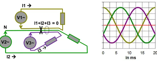
Fig. 2. – Three symmetric AC phases provide constant power flow with 50% less conductor material.
rule of thumb that states that the transmission voltage is of the order of one kilovolt per each kilometer of transmission distance.
The need for high voltage can be quickly illustrated with a numerical example. While the transferred power is voltage times current,Ptrans=U I, the resistive losses go with the square of the current, Ploss = RI2. For the conductor of the figure, with a cross section of 10 cm2of aluminium per phase, the resistanceRis 0.03 Ω/km and hence, at the maximum current of 2600 A, the resistive lossesPlossare 200 kW/km. If the transmission voltage was only 380 V, the transmitted power Ptrans would be one megawatt and the loss 20% per kilometer. In contrast to this, at a transmission voltage of 380 kV, the transmitted power is 1 GW, and the loss is 0.02% per kilometer.
There are considerable advantages from providing alternating current (AC) with three symmetric AC phases, each carrying a sinusoidal current of the same magnitude and frequency (50 or 60 Hz), but with the zero crossing displaced by one third of the period against each other (fig. 2). While the power is pulsating at twice the line frequency for each of the individual phases, it is a time independent constant for the sum of the three phases. As a consequence of trigonometry, the sum of the three currents is zero at any point in time, and the three return conductors that would be jointly placed at a common (zero) voltage can be omitted alltogether. This saves 50% of the conductor material for the same power transmitted! A further advantage of the three phase system was relevant in the early history of electrification: three phase asynchronous motors (that is induction motors) can provide torque even at standstill and are the more rugged motors compared to their single-phase equivalent.
self-inductance, are effects from the combined action of Ampere’s law — all electrical currents come with a surrounding magnetic field — and Faraday’s law — time-varying magnetic fields induce electric fields and hence currents in conductors (even in those conductors whose currents where the source of the magnetic fields in the first place). A major part of the physics of power systems — circuit parameters, transformers, motors, and generators — is contained in Maxwell’s equations plus the Lorentz force equation.
It might appear to be a marginal detail that power lines come with a parasitic self-inductance, but this fact is a strict constraint to the transmission capacity of power lines at distances beyond about 80 km (below that distance the capacity is limited by thermal considerations). As most loads, in particular induction motors, are also of inductive type, power systems need sources that are of the opposite, capacitive type. Power system engineers talk of inductive components, where the current is lagging the voltage, as “consuming reactive power” and capacitive elements, where the current is leading the voltage, as “providing reactive power”. This is a notational convention. Physically, reactive power is the flow of energy in each phase oscillating back and forth between the (parasitic) inductances and the generators.
The larger effective diameter of the conductor is also beneficial in a third way. It leads also to lower electric fields at the conductor surface and reduces the amount of corona discharges. This is one of the phenomena associated with the presence of high voltages. Choosing the proper high voltage insulation is essential for a good design of power system components.
High-voltage insulation is a science and a craft with the aim to limit the risk of a destructive breakdowns of the insulation medium [3, 4]. A typical electric breakdown field strength,e.g.of dry air at one bar, is 3 kV/mm. Beyond that field strength the gas molecules become ionized to a sufficient degree to form a conducting path between the electrodes carrying the voltage. The special insulation gas sulfur hexafluoride at 6 bar has 50 kV/mm breakdown field strength, the solid insulators porcelain and epoxy resin have 30 kV/mm breakdown field strength.
In order to limit the electric-field strength, those high-voltage carrying metallic parts that geometrically define the shortest insulation distance are usually given a shape “as round as possible”. This is evident for the corona ring electrodes in fig. 1. Another visual effect of the high-voltage design is the increase of the creepage path with sheds (umbrella structures) at surfaces that connect high-voltage electrodes, as can be seen for the suspension insulators in fig. 1. Details of overhead transmission lines are described, e.g., in ref. [5].
3. – Transformers
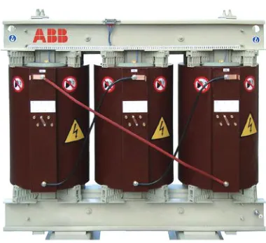
Fig. 3. – A typical three-phase dry distribution transformer, high voltage: 20 kV, low voltage: 415 V.
distribution, and consumption of electric power. Power transformers were the enablers of regional AC power grids around 1880, the transformation of DC voltages is more expensive and less efficient until today.
In a transformer, the alternating current of the primary winding produces an alternat-ing magnetic field in the steel core that produces an alternatalternat-ing current in the secondary winding. The current ratio (and, inversely, the voltage ratio) is determined by the ratio of turns of the primary and the secondary windings. A real power transformer does look different from a textbook transformer in some ways. A good introduction provides ref. [6].
There are three phases and, for an analogous argument as with the neutral conductor in electric three phase circuits (cf. fig 2), the sum of the magnetic return fluxes of the phases cancels by trigonometry. Hence there is no return leg for any of the phases, and a balanced three phase transformer saves 50% of the steel core material compared to three single-phase transformers of the same rating.
For each phase, high-voltage and low-voltage windings are coaxially arranged around the steel core leg. Coaxial arrangement reduces the leakage flux, that is the part of the magnetic flux generated by the primary winding but not penetrating the secondary winding, thus “leaking” out of the transformer. Here is a profound difference between the electrical and the magnetic properties of matter. While the electrical conductivity of metals is more than 20 orders of magnitude higher than that of air and other insulators, the magnetic permeability, which is the equivalent conductivity for magnetic circuits, is only 2000 times larger in iron (μ = 2000) than in air (μ = 1). For this reason, all transformers have a significant leakage flux and behave from the electric circuit point of view like an inductive coil, consuming reactive power.
The amount of core steel is defined by the magnetic saturation field intensity. Be-yond saturation, the magnetic domains in the iron steel are aligned, and the magnetic permeability decreases towards one. In that case, the leakage inductance would become intolerable, and the nonlinear permeability transition would induce distortions in the si-nusoidal current waveforms of the primary and the secondary windings. For that reason, power transformers need to be designed such that the core steel remains unsaturated at nominal operation. The saturation magnetic field for power transformer steels is typically about 1.5 T.
Transformers have losses between 0.3% and 3% of the nominal power. On one hand, there are the ohmic losses in the conductors that increase with increasing load currents. On the other hand, there are the “no load losses” that occur even when no load is supplied at the secondary side of the transformer. The reduction of no load losses is very important in the transformer design, because many transformers spend a large proportion of their time at low load conditions. Among the no load losses are the hysteresis losses in the core steel due to the changing sign of the magnetic field and the induced eddy currents in the structural steel (needed for mechanical fixation). A particular design measure to reduce no load losses is the lamination of the core steel in 0.3 mm thin sheets to block eddy currents.
4. – Synchronous generators
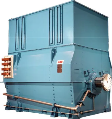
Fig. 5. – A synchronous generator.
Figure 6 shows, three times, a cut through a two pole synchronous generator perpen-dicular through the axis of rotation pointing out of the drawing plane. The stator of the synchronous generator is composed of the three windings of the three stator phases connected to the power grid. The conductors of those windings, the stator bars, are mainly parallel to the axis of rotation and the current is either pointing into or out of the drawing plane. The rest of the winding that lies parallel to the picture plane and closes the current path of the coils is not shown. The winding conductors are distributed in such a way that each phase covers about one third of the circumference displaced (for a two-pole machine) by 60 degrees.
N
S
a) Under-excited b) Over-excited c) Generator mode Uout
Vout
Wout
Uin Win
Vin
The inner cylinder is the rotor. The rotor windings are supplied by direct current so that they create a steady magnetic field, such as a permanent magnet would do. This magnetic field rotates in fixed relationship with the rotor and the turbine wheel that is attached to the shaft and induces currents in the stator windings. As evident from their name, synchronous machines turn with the frequency of the AC power grid they are connected to, such that in steady state there is a constant angle between the rotating magnetic field created by the rotor excitation and the magnetic field created by the grid voltage at the stator windings. It depends on the magnitude of the direct current fed to the rotor windings and the corresponding size of the rotor field whether the synchronous generator supplies or consumes reactive power, and it depends on the angle between rotor and stator whether the synchronous machine behaves as a generator providing real power or as a motor consuming real power.
At the left hand side of fig. 6, the rotor excitation is small (under-excitation) so that the field resulting from the grid voltage dominates. In that case the machine “looks” for the grid like a three-phase inductance and consumes reactive power. The currents through the stator windings are lagging the grid voltage at the terminals of the stator windings by a quarter of the period. Reactive power oscillates for each phase back and forth between the grid and the magnetic field created by the stator currents. The reactive power supplied by the grid comes most likely from some other synchronous generators operated in the over-excited mode discussed now.
If the magnetic field from the rotor is stronger than the field resulting from the grid voltage (over-excitation, fig. 6b), the currents through the stator windings reverse their sign and lead the grid voltage, — as if the generator was a three phase capacitor. Now it is supplying reactive power to the grid, maybe to some generator operated in under-excitation mode, but more likely to the stray inductances of induction motors, power lines, and transformers. Both kinds of reactive power are mere oscillations with the double of the grid frequency, the average power in both cases is zero.
If the turbine provides some torque and accelerates the rotor, there will open up an angle between the rotating magnetic field created by the rotor excitation and the magnetic field created by the grid voltage at the stator windings (6c). Now, the stator current will be partially in phase with the voltage accross the stator windings and supply real power to the grid. This is the mechanical power that is converted to electrical power in the generator. The automatic control of the infeed of reactive and real power from synchronous generators keeps the electric power system in balance at all times.
5. – Circuit breakers
Fig. 7. – A high voltage circuit breaker (three-phase live tank breaker, 170 kV, 3150 A, 40 kA).
A circuit breaker is an ideal conductor when it is in the closed position and an ideal insulator when it is in the open position, and it can ensure a reliable transition between these two states at any short-circuit current level that the grid location might provide. Circuit breakers are based on air as the switching medium at low voltage (below 1000 V), mainly on vacuum and metal vapour in medium voltage (between 1000 V and 36 kV) [7], and mainly on the special insulation gas sulfur hexafluoride in high voltage (36 kV to 1100 kV) [8].
Figure 7 shows a three phase high voltage live tank circuit breaker for a nominal volt-age of 170 kV, a permanent current of 3150 A, and a short-circuit interruption capability of 40000 A. From outside, one recognizes the flexible conductors going to the top and the bottom of the circuit breaker. The circuit breaker is mechanically supported and insulated from the ground by a support insulator that is in this case of the same size as the circuit breaker itself. Circuit breaker and insulator are embedded in epoxy insula-tion with sheds. At the right, one recognizes the mechanical drive where the mechanical energy for the movement is stored in springs and where a tripping mechanism initiates the mechanical movement of the contacts when the logic has decided that the breaker should interrupt.
Fault Voltage
Current
1
2 3 4
5
Current Voltage
3
1 2 4 5
1 s 20 ms
B A
C
Fig. 8. – Bottom: A cut through the interruption chamber of a high-voltage circuit breaker at different moments during current interruption. Top: Current and voltage waveforms during interruption with a zoom (right) into the moment of interruption. Letters designate parts of the breaker, figures different moments in time.
nominal contacts that have a very low contact resistance carry the current with low losses. Upon the detection of a short circuit, both contacts move, first separating the nominal contacts and commutating the current to the arcing contacts. When the arcing contacts separate (1), a hot plasma arc is drawn in the gap, and the short-circuit current continues to flow through it, providing an enormous amount of heat so that the plasma stays conductive. During the so-called high current phase (2), some part of the energy is used to build up pressure in dedicated volumes. There are also pistons that provide additional pressure from their movement. Shortly before current zero (3) the gas flow reverses and cools the arc convectively as the arc shrinks with the declining current. At current zero (4), with sufficient cooling flow provided, the current is interrupted, and the gap between the contacts (and also the chamber insulator, C) has to sustain immediately the recovery voltage (5). In a successful interruption, the dielectric strength of the gas recovers faster than the recovery voltage of the network rises. Otherwise, in the case of a failed interruption, there will be a breakdown, and the arc will reignite.
We have tried to give a comprehensible description of the four most important com-ponents of electric power systems. Overhead transmission lines enable the long-distance power transmission at low losses. Transformers allow to select the adequate voltage levels for generation, transmission, distribution, and consumption of electricity. Synchronous generators control the real, active, and the reactive power flow. Circuit breakers can interrupt short circuits and disconnect grid segments with a fault.
The continental European grid extending from Poland to Portugal is, capacity-wise, the largest synchronous power grid of the world. Interconnected power grids are a re-markable engineering success and achievement of our societies.
∗ ∗ ∗
For preparing this lecture I have used the slides and the insight of many of my col-leagues at ABB Corporate Research, namelyMarkus Abplanalp, Thorsten Stein-metz, Riccardo Bini, Martin Seeger, Mats Larsson, Alexander Horch, and Willi Paul.
REFERENCES
[1] Munoz R., Valero S., Lopez D.andSenabre C.,Overview of the Quality of Electricity Supply in Spain, in International Conference on Renewable Energies and Power Quality, Las Palmas, 2011.
[2] Mohan N.,Electric power systems: a first course(Wiley, New York) 2012.
[3] Arora R.andMosch W.,High voltage and electrical insulation engineering (Wiley, New York) 2011.
[4] K¨uchler A.,High voltage engineering: fundamentals, technology, applications (Springer, Berlin) 2013.
[5] Bayliss C. R.,Transmission and distribution electrical engineering(Newnes, Oxford) 1999. [6] Winders J. J.,Power transformers: principles and applications(Marcel Dekker, New York)
2002.
[7] Slade P. G.,The vacuum interrupter: theory, design, and application (CRC Press, Boca Raton) 2008.
[8] Garzon R. D.,High voltage circuit breakers: design and applications(Marcel Dekker, New York) 1997.