http://www.sciencepublishinggroup.com/j/ajce doi: 10.11648/j.ajce.20170504.17
ISSN: 2330-8729 (Print); ISSN: 2330-8737 (Online)
Research on the Vertical Setback Problem of Steel Bundled
Tube Structure
Hao Yong
1, 2, Li Yansong
2, Jiu Zhenggang
2, Zhang Tao
3, Wang Futian
4, Zhang Xusheng
41The Key Laboratory of Urban Security and Disaster Engineering, Beijing University of Technology, Beijing, China 2
College of Civil Engineering, Hebei Insititute of Architecture and Civil Engineering, Zhangjiakou, China
3Department of Building Engineering, Qiqihar Insititute of Engineering, Qiqihar, China 4Zhangjiakou City High-Grade Highway Asset Management Center, Zhangjiakou, China
Email address:
[email protected] (Hao Yong)
To cite this article:
Hao Yong, Li Yansong, Jiu Zhenggang, Zhang Tao, Wang Futian, Zhang Xusheng. Research on the Vertical Setback Problem of Steel Bundled Tube Structure. American Journal of Civil Engineering. Vol. 5, No. 4, 2017, pp. 235-241. doi: 10.11648/j.ajce.20170504.17
Received: June 28, 2017; Accepted: August 4, 2017; Published: August 14, 2017
Abstract:
To study the mechanical performance of steel bundled-tube structures and find the reasonable setback scheme, the 18 calculation model with different setback based on the same bottom, height as well as the volume were designed. The effect of different setback methods on performance indexes such as natural vibration period of the structure, stiffness was analyzed. Stress total enhancement ratio and reference enhancement ratio are introduced to study the distribution rule of the spandrel beam stress under different vertical setback methods. The distribution rule of column stress was also analyzed. The results show that the changing rule of the equivalent wind effect coefficient is the same as the basal shearing force and basal anti-overturning moment. Reference enhancement ratio of the spandrel beam is a fixed value at a certain height and volume. Total stress enhancement ratio of the spandrel beam is mainly related to the remained height. Vertical setback causes abrupt stress in the columns. The setback influence on the columns is less than that on the beams, and the abrupt stress stories are also less. It is advised that the location of the initial setback should be as far as possible from the embedded end. The reasonable setback method should be uniform and symmetric.Keywords:
Steel Bundled-Tube, Vertical Setback, Mechanical Performance, Stress Enhancement Ratio1. Introduction
The forms of structural vertical setback mainly includes setback in the middle height of an elevation plan, setback in a small tower at the top, setback on the roof of a skirt building, etc. As for mechanical characteristics, lateral load is the control element of high-rise building structure design. A steel bundled-tube structure is generally used in high-rise building structures. When stiffness decreases vertically, setback in the vertical influences the mechanical performance of the whole structure more obviously. Due to the particularity of the bundle tube structure (setback based on single-cylinders), most of the setbacks would result in an irregular plane concave and convex structure or weight and geometry irregular structure in the vertical [1-2]. The current study on setbacks in vertical includes the following:
spatial finite element model or specified on the bundled-tube structure, studying how the all kinds of setbacks influences structural deformation patterns and mechanical properties. There is also no research on how setback is the most reasonable.
By analyzing different bundled tube structure models with different methods of setback, this study analyses the influence of different methods of setback on the stress and deformation performance of bundled tube structures, and discuss a reasonable method of setback for bundled tube structures; providing a reference for similar engineering designs.
2. Basic Calculation and Setback Model
In order to highlight research priorities, this study designed a series of models that have the same bottom plane size, structural height and body weight, excluding the basic calculation model without setback. A different setback method was only considered.
2.1. Introduction Oft He Basic Calculation Model
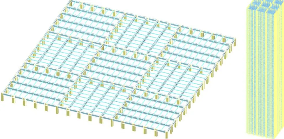
The bundled-tube structure is 100 stories above ground, has a story height of 3.6 m, and the height of the structure is 360 m. The plan form of the structure is shown in Figure 1.
Figure 1. The example model 01 schematic diagram.
The height-width ratio is 5.3. The plan of the bundled-tube is formed by nine frame tubes. The bottom size of the bundled-tube is 67.5 m × 67.5 m. A single frame tube is 22.5 m × 22.5 m. Column spacing is 4.5 m. The steel adopts Q 420. The intensity degree of the floor concrete is C 30. The dead load of the building surface is 3.0 kN/m2, and the live load is 2.0 kN/m2. Basic wind pressure is 0.45 kN/m2 and thickness of the reinforced concrete floor adopts 110 mm. Ground roughness ranks Class C. For seismic resistance, the anti-cracking degree is supposed to be seven, the earthquake is grouped into number one, and the site classification is classified into Class II. The section sizes of members are shown in Table 1.
2.2. Designed Model of the Setback
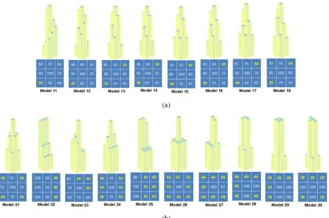
Based on the calculation example, the designed model of setback can be divided into two categories: series 1 and series 2. The setback adopts the format on the premise of the same
bottom, height as well as the volume. Models of series 1 shrink evenly in general after setback from the first floor. However, the format of the setback is classified intohelix, symmetric in proper sequence, symmetric synchronization, as well as the combination of the formats above. Models of series 2 can shrink in place with three, two or one step; and the setback is more than one cylinder unit. the designed model of setback is shown in Figure 2.
Table 1. Section sizes of members.
Membername Section Size story
Corner column box 1,300 × 1,300 × 100 × 100 × 100 1-100
Side column I
1,400 × 900 × 90 × 100 1-30
1,400 × 900 × 60 × 80 31-60
1,400 × 900 × 40 × 60 61-100
Spandrel beam I 1,000 × 400 × 50 × 70 1-60
1,400 × 900 × 35× 50 61-100
Figure 2. Different methods and start locations of setback.
3. Comparative Analysis of Mechanical
Performance on the Models with
Setback
3.1. Analysis and Comparison of Structural Overall Mechanical Performance Indexes
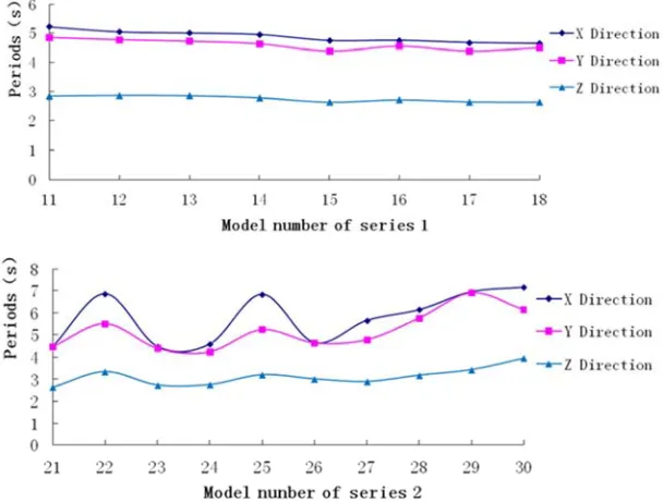
Based on modal and elastic analysis under lateral loads, comparison of setback model periods is shown in Fig. 3.
Among the models of series 1 that shrink in the vertical direction, the minimum of the first translation on X direction in the natural vibration period is model 18, the value of which is 4.65 seconds, and the maximum of that is model 11, with a value of 5.23 seconds, showing the difference of those two is 12.5%. Among the models of series 2, the minimum is model 21, the value of which is 4.46 seconds, the maximum is model 30, with a value of 7.16 seconds, the difference of those two is 161%. The mere variable ways for vertical setback can result in the obvious difference in lateral stiffness in the vertical direction. Therefore, it can be seen that the influence of the vertical setback to the structural overallindexes cannot be ignored.
Under the premise of isovolumetric and uniform vertical setback, the changing rule of the natural vibration period for models of series 1 in the previous three stages are mainly identical. Generally, the vertical setback of higher starting floor, in other words, the start point of the setback is relatively far from the basal fixed end, the structural stiffness is stronger, and the natural vibration period is smaller, which can be
thought that the bundled tube structure is assumed as a cantilever component in the vertical direction. When the setback is far from the fixed end, it is equivalent that restraint of the end region for this cantilever is stronger. Under the circumstance that other factors are similar, the stronger the end restraint is, the greater the lateral load resistance would be, and the circle would become shorter. The longer the distance between the initial position and the fixed end is, the stronger the stiffness would be. When evenly setback with the same height, volume as well as the initial point, the stiffness would basically be the same, and the methods or times for the setback have less influence on that.
Figure 3. Comparison of setback model periods.
Figure 4. Comparison of effective quality factor in the X directional translation.
Figure 4 illustrates the comparison of effective quality factor in the X directional translation of both the previous four stages and the 10th stage in the vertical model and none setback model 01. Results revealed that after structural vertical setback, influence from the lower mode of vibration would be decreased, while the upper mode of vibration would be increased
3.2. Analysis and Comparison of Spandrel Beam Stress
The vertical setback part of model 11 is chosen and curve for changes of the partial stress ratio in the spandrel beam along with the story of the structure is shown in Figure 5.
Figure 5. Changes of stress ratio in partial spandrel beam of model 11.
stress would occur when a position where shrinkage exists is reached. The basic regularity of every stress curve is that at the bottom, which is far from the setback position, the rising rate of stress would be lower, compared with that close to the vertical setback position. The rising rate of stress is fastest in the spandrel beam when 5-10 stories continue to remain before reaching the vertical setback position. Moreover, peak Two parameters were introduced to analyze the peak value of the regional stress ration: stress total enhancement ratio and stress reference enhancement ratio. Stress total enhancement ratio refers to the ratio of the certain spandrel beam stress ratio (peak) at the setback and the same position spandrel beam stress ratio at the first story. Stress reference enhancement ratio refers to the ratio of the stress total enhancement ratio and representative value of the remaining stories. For example, if the remaining number of stories is 30,
then the representative value is 3. The remaining stories refer to the adjacent remaining stories of the setbacks, and the larger value between the X and Y direction is chosen. If the X or Y direction value is below or equal to 10, it is acceptable to choose the larger value of oblique direction. The height of the remaining stories is called the remained height.
Figures 6 shows the stress total enhancement ratio and reference enhancement ratio curves of the spandrel beam at setbacks in the models. The abscissa is the story number, the ordinate is the stress enhancement ratio, the red curve is the spandrel beam stress total enhancement ratio at setbacks, and the blue curve is the reference enhancement ratio. From the curve in the figure, the spandrel beam stress total enhancement ratio at setbacks generally goes downwards as the story rises. The reference enhancement ratio does not change much.
As analyzed from the data curve of Figures 6, the spandrel beam’s stress enhancement ratio at setbacks is within 2-3. This means that the spandrel beam’s stress enhancement ratio is a fixed value at a certain height and volume with no relationship with the setback method. The spandrel beam total stress enhancement ratio (spandrel beam peak stress after the partial setback) is mainly related to the remained height. Based on this conclusion, in the process of similar structure designs, the spandrel beam peak stress ratio at the setbacks can be preliminarily estimated, just like the stress ratio curve peak depicted in the figures.
3.3. Column Stress Analysis and Comparison of the Vertical Setback Model
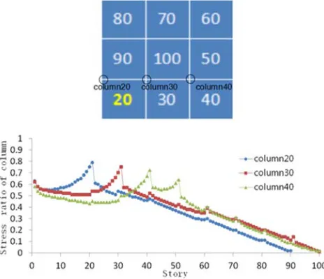
Vertical setback stories of model 11 and story 20, 30 and 40's design control stress ratio value conditions are presented in Figure 7. In columns that run vertically from down to up along the stories, the stress ratio generally presents a downward trend. Every time the columns pass a setback region, abrupt stress is caused; which is presented as the sharp peak in the figure. The setback structure column’s abrupt stress would extend upward and downward for several stories, compared with none setback models. Setback influence on the columns is less than that on the beams, and abrupt stress stories are also less.
Figure 7. Changes of stress ratio in partial column of model 11.
Column stress due to vertical setback generates a partial stress peak, which usually reach its peak value at the setback story. This kind of abrupt stress condition would influence 3-5 stories and 1-2 stories above. As the story rises, the number of vertical setback of the element connected with the columns equal to the number of peak stresses.
4. Conclusion
After structural vertical setback, influence from the lower mode of vibration would be decreased, while the upper
mode of vibration would be increased. Reference enhancement ratio of the spandrel beam is a fixed value at a certain height and volume with no relationship with the setback method. Total stress enhancement ratio of the spandrel beam is mainly related to the remained height. Vertical setback causes abrupt stress in the columns. The setback influence on the columns is less than that on the beams, and the abrupt stress stories are also less. The vertical setback location of the bundled tube structure should be away from the embedded-end, and the stiffness difference formed by the setback should not be too large. Uniform symmetrical setback is preferred.
References
[1] Federal Emergency Management Agency. FEMA 368: NEHRP Recommended Provisions for Seismic Regulations for New Buildings and Other Structures [S]. Federal Emergency Management Agency, Washington, D. C., 2001.
[2] JGJ 3-2010 Technical specification for concrete structures of tall building [S]. Beijing China Architecture and Building Press, 2010 (in Chinese).
[3] Kayikci, D. The Behavior of Moment Resisting Steel Frame Under Seismic Excitation With Variation of the Geometric Dimensions of Architectural Setbacks [D]. Ph. D. Thesis, UniveLsity of Miami, 2011.
[4] Al-Ali, A. A . K., Krawinkler, H. Effect of Vertical Irregularities on Seismic Behavior of Building Structures [D]. Ph. D. Thesis, Stanford University, 1998.
[5] Varadharajan, S., Sehgal, V. K, Saini, B. Determination of Inelastic Seismic Demands of RC Moment Resisting Setback Frames [J]. Archives of Civil and Mechanical Engineering, 2013, (13): 370-393.
[6] Aranda, G. R. Ductility Demands for R/C frames Irregular in Elevation [C]. Proceedings of the 8th World Conference on Earthquake Engineering, San Francisco, California U.S.A., 1984.
[7] wood, S. L. Seismic Response of RC Frames With Irregular Profiles [J]. Journal of Structure Engineering, 1992, 118 (2): 545-566.
[8] H. Shakib and M. Pirizadeh. Probabilistic Seismic Performance Assessment of Setback Buildings under Bidirectional Excitation [J]. Journal of Structure Engineering, 2014, 140 (2): 04013061 1-11.
[9] Montazeri, S. M., Khaledi, F., Kheyroddin, A. A Study on Steel Monment Resisting Frames with Setbacks: Dynamic Properties [C]. Proceedings of the 15th World Conference of Earthquake Engineering, Lisboa, Portugal, 2012.
[10] Xiao C Z, Xu P F, Wang C K. Research on the Influence of Setback to Seismic Performance of High-rise Building Structures [J]. Building Structure, 2003, 33 (9): 12-15. (in Chinese).
[12] Lu D Y, Liu C, Jiang W W, et al. Influence analysis of the setback on the seismic performance of the multiple complicated super high-rise structure [J]. Building Structure, 2014, 44 (18): 14-17. (in Chinese).