Development of Extended Two-Point Model for Asymmetric
Scrape-O
ff
Layer
∗
)
Apiwat WISITSORASAK
1,2), Sébastien KAHN
3), Bernard PÉGOURIÉ
3),
Jean-Francois ARTAUD
3), Guido CIRAOLO
3)and Cédric REUX
3)1)Department of Physics, King Mongkut’s University of Technology Thonburi, Bangkok, Thailand 2)Theoretical and Computational Science Center, King Mongkut’s University of
Technology Thonburi, Bangkok, Thailand 3)CEA, IRFM, F-13108 Saint-Paul-les-Durance, France
(Received 8 January 2019/Accepted 22 July 2019)
The SYCOMORE code is a modular system code which aims at modelling future fusion power plants with all subsystems and to provide a global view of the whole plant. The code consists in different modules handling the different subsystems of the plant, from the core plasma to the conversion of heat to electricity. Among them, the divertor is one of the most important components and must withstand high heat load. While the complex magnetic configuration in tokamaks and the peculiar transport in the scrape-offlayer (SOL) give rise to an asymmetry in the high field and low field energy fluxes, this issue should be properly addressed in SYCOMORE for quick and reliable predictions. In this work, the SOLDIV code which is a scrape-off-layer and divertor module in SYCOMORE has been used to investigate this asymmetry problem based on an extended two-point model. When the outgoing fluxes of particles and heat from the plasma core enter the SOL at the stagnation point, they split into two parts: one transporting to the inner divertor, and the other transporting to the outer divertor. By introducing the imbalance factor of the energy flux between the two divertor plates, the transport equations become a set of nonlinear equations that can be numerically solved for the densities and temperatures at both divertor plates and the stagnation point. Strong temperature and density differences at the targets can be found. The analysis results are validated with the transport code SolEdge2D-EIRENE for WEST test discharges. The simulation results for ITER are also investigated.
c
2019 The Japan Society of Plasma Science and Nuclear Fusion Research
Keywords: divertor, SOL-divertor, system code, two-point model, balloon transport DOI: 10.1585/pfr.14.3403150
1. Introduction
Fusion energy is a highly promising potential candi-date that offers an almost inexhaustible source of energy for future generations, and low environmental pollution. However, one of the greatest challenges in the success of the magnetic confinement fusion devices, such as ITER and DEMOs, may be related to the turbulent dynamics of the plasma in the scrape-off layer (SOL), the narrow region surrounding the core plasma where the magnetic field lines are open and terminate on the vessel of the de-vice [1–3]. The plasma behaviour in this region not only governs the overall confinement properties of the device, but also regulates the impurity dynamics which can di-lute the fusion fuel and radiate a part of the plasma en-ergy content [4]. The SOL plasma also determines the conducted/convected power exhausted at the reactor vessel walls [5]. This issue is critically important since a too high heat load can severely damage the plasma-facing material
author’s e-mail: [email protected]
∗)This article is based on the presentation at the 27th International Toki
Conference (ITC27) & the 13th Asia Pacific Plasma Theory Conference (APPTC2018).
which can make fusion reactors not economically attrac-tive or even feasible. While diagnostic access for the SOL plasma is difficult and is limited, simulation of the plasma dynamics in the SOL region has proven to be an invaluable tool to address the physics of this region.
The simulation of a whole tokamak is a complex prob-lem because it involves different phenomena and all sub-systems are not entirely independent from each other. In order to understand and design a whole fusion plant, a fast and reliable simulation code is inevitable [6, 7]. The SYCOMORE code is a modular system code which aims at modelling future fusion power plants with all subsys-tems and to provide a global view of the whole plant [8, 9]. The code consists in different modules handling the diff er-ent subsystems of the plant, from the core plasma to the conversion of heat to electricity [10]. The divertor is one of the most important components of the reactor and may be exposed to excessive heat and particle fluxes. While the complex magnetic configuration in tokamaks and the peculiar transport in the SOL give rise to the asymme-try in the high field and low field energy fluxes [11, 12],
c
2019 The Japan Society of Plasma
this issue should be properly addressed in SYCOMORE for quick and reliable predictions. In this work, the SOL-DIV code which is a scrape-off-layer and divertor module in SYCOMORE has been used to investigate this asymme-try problem based on an extended two-point model. When the outgoing fluxes of particles and heat from the plasma core enter the SOL at the stagnation point, they split into two parts: one transporting to the inner divertor, and the other transporting to the outer divertor. By introducing the imbalance factor of the energy flux, the transport equations become a set of nonlinear equations that can be numeri-cally solved for the densities and temperatures at both di-vertor plates and the stagnation point . Strong temperature and density differences at the targets can be found. The analysis results are then validated with the transport code SolEdge2D-EIRENE for WEST discharges. The simula-tion results for ITER are also investigated.
This paper is organised as follows. We first describe the extended two-point model and the algorithm for solv-ing the model in section 2. Section 3 shows the comparison with the SolEdge2D-EIRENE code and simulation predic-tions for ITER. This work is summarised in section 4.
2. Methodology
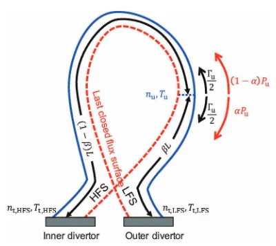
The basic two-point model describes the parallel transport along a magnetic field line [2]. The field line can simply be straightened to describe the transport in the parallel direction. This parallel transport is assumed to be decoupled from the perpendicular one. The most impor-tant feature of the two-point model is to relate the physi-cal quantities at two points: 1) the upstream point where the heat flux and particles enter the SOL, and 2) the di-vertor surface where the particles strike the solid material. In this model, the sources and sinks are treated locally at the boundaries. The locations of these two points are illus-trated in Fig. 1.
The two-point model can be directly derived from the fluid equations for plasma in steady state condition [2]. The particle and heat fluxes leave the core and enter the SOL at the upstream point. It is further assumed that neu-trals recycling from the targets are ionized in a thin layer in front of the target. For each side of the SOL flux tube, if it is assumed that the fraction of the momentum loss in the plasma flow is fmom[1], the total pressure throughout the entire length of the flux tube can be written as:
fmomnuTu(1+M2u)=ntTt(1+Mt2), (1) whereM is the Mach number, and the subscribesu andt refer to the values at the upstream and target. Here we also assume that the ion and electron temperatures are equal, Ti =Te. Note that the Mach number at the target,Mt, is approximately equal to unity. Equation 1 then becomes:
fmomnuTu(1+Mu2)≈2ntTt. (2) The total particle flux at the upstream point may be large during pellet-fuelling operation, and it may change the
up-Fig. 1 The particle flux,Γu, from the core enters the SOL and
equally separates into two parts. On contrary, the heat flux splits asymmetrically. The power to the outer and inner divertors areαPuand (1−α)Pu, respectively. The
connection length of the outer leg isβLand the connec-tion length of the inner leg is (1−β)L.
stream boundary significantly. One can define the parallel flux entering the SOL asG =(q95Γu)/(2πaκλ), whereq95 is the safety factor at 95% of the poloidal flux,Γu the to-tal rate of particle leaving the confined plasma volume,a the minor radius,κthe elongation, andλthe characteristic SOL width [13]. The parallel particle flux can be also writ-ten asG=nMcs, wherecsis the sound speed. In the SOL, the pressure conservation requires thatnT(1+M2) is con-stant along the field lines. In the heat transport equation, the parallel heat conduction generally dominates over the parallel heat convection [2]. Therefore the heat flux does not depend on the density and Mach number. Therefore the temperature remains unchanged, i.e.T =Tu. The pressure conservation at the upstream in the presence and absence of the particle fluxes can then be written as
nTu(1+Mu2)=nuTu. (3) Combining this equation with the expression ofG, one ob-tains
G(1+M2u)=nuMucs. (4) Solving forMuby using the quadratic formula, the Mach number at the upstream depends on the parallel particle flux as
Mu = 1 2
nucs/G−
(nucs/G)2−4
. (5)
After integrating along the field line of the flux tube, we finally obtain the heat transport equation [2]:
Tu7/2=Tt7/2+
7fcondqL 2κ0e ,
flux. Note that, in this model, no volumertric particle or power sources or sinks are considered. The ionization and recycling of neutrals are assumed to occurr only in a thin region near the target. Thus we write
(1−fpower)q,LFS =eγΓtTt,LFS
1+
γTt,LFS
, (7) where fpower is the fraction of the parallel heat flux that is lost before reaching the target, is the average energy lost by the electrons per recycled atom and approximately equals 25 eV [8], andγis the sheath heat transmission co-efficient,γ≈7 [2].
The asymmetries of the heat fluxe in the SOL can be modelled by introducing imbalance factors. The particle and heat fluxes enter the SOL at the upstream point, see Fig. 1. The precise location of the upstream is determined by the parameterβwhich is the fraction of the LFS con-nection length to the total length. The particle flux (Γu) from the core to the SOL then splits equally into two parts becausenu,left =nu,right,Tu,left =Tu,right, and the net Mach number equals zero at the stagnation point. One part of the fluxes goes to the outer target and the other directs towards the inner target.
For the heat flux from the core to the SOL, it enters the SOL at the upstream point as the particle flux does. We assume that it then splits asymmetrically into two parts. The amount of the power to the outer divertor isαPu, and the remaining power (1−α)Pu directs towards the inner target. The imbalance factors,αandβ, are inserted in the calculation of the two-point model leading to different sets of equations for the low-field side (LFS) and high-field side (HFS) as follows
for LFS:
2nt,LFSTt,LFS =nuTu,LFS ×(1+Mu2,LFS)fmom, (8) Tu7,/LFS2 =Tt7,LFS/2 +7fcondαqβL
2κ0e ,
(9) (1−fpower)αq=eγΓtTt,LFS ×
1+
γTt,LFS
, (10) for HFS:
2nt,HFSTt,HFS =nuTu,HFS×(1+M2u,HFS)fmom, (11) Tu7,/HFS2 =Tt7,/HFS2 +7fcond(1−α)q(1−β)L
2κ0e ,
(12) (1−fpower)(1−α)q=eγΓtTt,HFS
×
1+
γTt,HFS
. (13) At the upstream point, the densities and temperatures of the two field sides are equal. Therefore we have additional constrains at the upstream point.
nu,HFS =nu,LFS =nu, (14) Tu,HFS =Tu,LFS =Tu. (15)
In principle, the imbalance factors,αandβ, can be calcu-lated from kinetic theory.
The extended two-point model consists in a set of six nonlinear equations, equations 8 - 13, with 8 unknowns: nt,LFS,nt,HFS,Tt,LFS,Tt,HFS,Tu,nu, α and β. Since q is given from the core module HELIOS [14] andnu is the main control parameter, an additional parameter must be fixed for the system to be solved. It was chosenαin this work. For each set of equations, one can derive an ex-pression that only depends on the target temperature,Tt, as follows
Tt,LFS =
1+
γTt,LFS
−2
γ(1+MLFS2 )fmomnu
−2
×2miαq2(1−fpower)2
Tt7,LFS/2 +7fcondαqβL 2κ0e
4/7, (16)
Tt,HFS =
1+
γTt,HFS
−2
γ(1+M2HFS)fmomnu
−2
× 2mi
(1−α)q2(1−fpower)2
Tt7,/HFS2 +7fcond(1−α)q(1−β)L 2κ0e
4/7. (17)
Note that fmomis a function of the target temperature [1]. In this work, the conduction factor fcond is kept constant and approximately equals one. The target temperature (Tt) of each side can be independently determined as a func-tion ofαorβusing the bisection method [15]. Once the target temperatures at both targets are obtained, they are substituted back into the other equations to directly obtain nt at each side andTu. This can be done by the bisection method, see Fig. 2. By equating the upstream temperature from equations 9 and 12, and assumingTt,LFS > Tt,HFS, one can also obtain an inequality relation betweenαandβ:
α 1−α≤
1−β
β . (18)
Once the upstream temperature and density are deter-mined, the actual power lost in the SOL can be computed through impurity radiation. The heat balance between the upstream and the target points leads to the expression:
Fimp=
⎛ ⎜⎜⎜⎜⎜
⎜⎜⎝ fpowerq 2nuκ0eTu2
Tu
0 1
2T0.5LZ(T)dT
⎞ ⎟⎟⎟⎟⎟ ⎟⎟⎠
2
, (19)
whereFimp = fimp/Zeff [8]. AfterFimp is determined, the impurity fractionfimpis then obtained by
fimp=
Fimp
1−0.01FimpZimp(Zimp−1)
, (20)
where Zimp is the charge number of the seeded impurity [16], i.e. ZAr = 18 for argon. The integration in equa-tion 19, Tu
0 1
tends to overestimate the radiation losses. The value of fpowercorresponding to the impurity fraction can be finally obtained. Then the peak on the inner/outer divertor target qpeak,in/outis
qpeak,in/out=
Pseparatrix1−fpower−Prad,H Awet,in/out
+ fpowerPseparatrix
Awet,in/out
fdiv. (21)
Prad,H=e(−Ei)nt
2eTt mi
4πaλ
q95 is an hydrogen radiation power. Eiis the ionization energy of hydrogen (13.6 eV). Awetis the plasma-wetted area of a divertor. fdivis the frac-tion of radiated power from the SOL region that goes to the divertor walls. Since the peak heat flux on the target plates cannot exceedqthreshold=10 MW/m2(generally, limitation occurs at the outer divertor) [18], an impurity such as argon is introduced (parameter fimp) for increasing the radiation in the SOL and limiting the heat load on the targets [19].
The work flow of the algorithm for solving the ex-tended two-point model is illustrated in Fig. 2 and is im-plemented in the new SOLDIV subroutine. This subrou-tine initially takes inputs including geometric parameters (R,a,L, λ,Awet,q95), the power crossing the separatrixPu, the additional parameter α or βrequired for solving the system of equations as explained above, and a first guess for the impurity fraction fimp. The upstream density,nu, is
Fig. 2 The flow chart describes the work flow for solving the extended two-point model. Note thatδdenotes the toler-ance of the temperature difference andqthresholdrepresents
the threshold value of the heat flux on a divertor target.
the control parameter chosen by the operator from physical considerations (generally a fraction of the pedestal density defined in the HELIOS core module).
3. Result and Discussion
3.1
Comparison with SolEdge2D-EIRENE
code simulation
In this section, we validate the simulation results from the extended two-point model with the transport code SolEdge2D-EIRENE. SolEdge2D is a two-dimensional transport code for simulating the edge plasma with com-plex and realistic 2D magnetic and wall geometries [20, 21]. Its calculation is based on a fluid model that includes the conservation equations for the particles, for the mo-mentum, and for the energy for both electrons and ions. It also assumes toroidal-axis symmetry and the compu-tational domain is then reduced to a 2D poloidal cross-section. SolEdge2D can be coupled with EIRENE to in-vestigate edge plasma transport, thermal exhaust and de-tachment behavior in tokamak devices [22].
In order to compare the results from the two codes, the two-point model takes the upstream density and the power through the separatrix from the SolEdge2D-EIRENE code as input parameters. The two-point model is then used to predict the upstream and target temperatures, and the tar-get densities. Simulation results of two WEST discharges, 53259 and 54034, are chosen for the comparison. Table 1 shows the summary of these two discharges. We note that the discharges labelled 54034A and 54034B are from the same discharge, but with different phases. For the WEST configuration, the plasma major radius isR = 2.5 m, the
Table 1 Summary of SolEdge2D-EIRENE code simulations for WEST test discharges. Note that Psep is the power
through the separatrix [MW],Prad,SOLis the total power
radiated in the SOL [MW],λqis the scale length for the
power decay [mm]. The densities are reported in a unit of 1019m−3, and the temperatures are measured in a unit
Fig. 3 Comparison of the simulation results between the extended two-point model (2PM) and the transport code SolEdge2D-EIRENE.
minor radius a = 0.5 m, the elongation κ = 1.54, the toroidal magnetic fieldBφ=3.6 T and the plasma current IP=0.50 MA.
Figure 3 shows the comparison of the simulation re-sults of the densities and temperatures for the two dis-charges as obtained by the two codes. The temperatures at the upstream (Tu), and the inner (Tt,HFS) and outer (Tt,LFS) targets are illustrated in the top row, and the densities at the upstream (nu), and the inner (nt,HFS) and outer (nt,LFS) targets are presented in the bottom row. As we can see in these plots, the calculation from the extended two-point model overall agree with the SolEdge2D-EIRENE simula-tion.
We also compute the percentage differences between the results from both simulation codes. Here the percent-age difference is defined as
Δ(%)≡ f2PM− fSolEdge fSolEdge
×100, (22)
where f2PM and fSolEdge denote the same physical quanti-ties of the plasma (i.e. nt,HFS,nt,LFS,Tu,Tt,HFS, andTt,LFS) which are obtained from the two-point model (2PM) and the SolEdge2D-EIRENE simulation, respectively. We fur-ther note that, in this part, the fraction of power to the low-field side (α) is determined by optimising the total percent-age differences of the densities and temperatures at the up-stream point and the inner and outer targets. These imbal-ance factors are presented in Table 3. Whenαis not equal to 0.50, the differences of the densities and temperatures at the targets become more obvious. Table 2 shows the per-centage differences for these discharges and their average. As a whole, the average percentage difference for the den-sities and the temperatures at the upstream and the targets are less than 18%.
This work only compares the calculation from the ex-tended two-point model with SolEdge2D-EIRENE simu-lation on test discharges from WEST. However, it is a
Table 2 The percentage differences of the densities and temper-atures of the two discharges from the two-point model and SolEdge2D-EIRENE.
Table 3 The fraction of the power to the LFS (α) and the fraction of the LFS to the total connection length (β) as calcu-lated from the extended two-point model.
necessary step before comparing with experimental data since we have more control over parameters and physics involved. Future work should validate the model with ex-periments.
3.2
Prediction for ITER
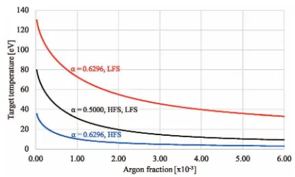
Fig. 4 The simulated target temperatures at the inner and outer divertors of ITER as a function of the argon fraction.
=6.20 m, the minor radiusa=2.00 m, the plasma current IP =14.4 MA, the toroidal magnetic fieldBT =5.3 T, the safety factor at the 95% of the poloidal fluxq95 =3.0, the radiation powerPrad=33 MW, the power crossing the sep-aratrixPu=92 MW, and the density at the upstream point nu=4.00×10¹⁹m−3.
It is further assumed that argon is the seeded impurity. Experimentally one observes that the asymmetric ratio be-tween the power to the outer divertor and the power to the inner divertor can vary on a significant range, from 1:1 to 5:1 [23]. This ratio could be reduced if we allow neutral particles to commute between the two legs. As a repre-sentative average value, we usePLFS/PHFS = 1.7, it cor-responds to an asymmetry power parameterα=0.6296. Figure 4 shows the predicted temperature at the inner and outer targets as a function of the argon fraction for α = 0.6296 and 0.50. The corresponding values of the peak heat flux on both divertor targets are plotted in Fig. 5. By construction, whenα=0.5, the temperatures on both divertor targets are the same. This is due to the symme-try of the particle and heat flux entering the SOL. Since the inner target has smaller plasma-wetted area, the peak heat flux on the inner divertor is higher than that on the outer divertor, see equation 21. The differences of the tem-peratures and heat fluxes at both divertor targets become more pronounced when the power fraction (α) deviates fromα = 0.5, see Figs. 4 and 5. In this case, both target temperature and peak heat flux on the outer divertor are higher than those on the inner divertor. The graphs show that the temperature and peak heat flux are decreasing as the argon fraction increases.
From Fig. 5, we also found that if the argon fraction is too low, the peak heat flux on the outer divertor may ex-ceed the threshold value which is about 10 MW/m2 [18]. An impurity such as argon should be introduced in the re-gion near the divertor. We found that the minimum concen-tration of argon required to keep the peak heat flux on the divertors below 10 MW is about 4.85×10⁻³in agreement with more sophisticated simulations [24, 25].
Fig. 5 The simulated peak heat fluxes at the inner and outer di-vertors of ITER as a function of the argon fraction. A dashed line denotes the threshold heat flux at the targets.
4. Summary
SYCOMORE is a system code that aims at modelling future fusion power plants with all subsystems included. It consists in a number of modules describing the diff er-ent componer-ents of the reactor, that are all interconnected. For the computation of the density and temperature in the scrape-offlayer, the SOLDIV code is used. However the previous version of SOLDIV assumed a symmetric SOL. In reality there is an imbalance of the heat flux between the two divertor legs, due to the ballooned transport, outward compression of the magnetic surfaces due to the Shafranov shift and asymmetry in the plasma wetted areas in the di-vertor. In this work, the SOLDIV module is improved to investigate this asymmetric transport in the SOL based on the extended two-point model. It is assumed that the out-going fluxes of particles and heat from the plasma core en-ter the SOL at the upstream point whose location is deen-ter- deter-mined as a fraction of the connection length (β). The heat and particle fluxes then split into two parts: one flowing to the inner divertor, and the other towards the outer divertor. By introducing the imbalance factors of the energy flux (α) and connection length (β), the transport equations become a set of nonlinear equations that can be numerically solved for the densities and temperatures at both divertor plates and the upstream point. We note that ELMs are not taken into account in this work. The two-point model is then vali-dated with the transport code SolEdge2D-EIRENE for two WEST discharges. The densities and temperatures at the upstream and targets that are computed by the two codes agree within the average percentage difference of 18%. Last but not least, the predictions of the densities, temper-atures, and heat fluxes at both divertor targets of ITER are also reported. To keep the heat flux on the outer diver-tor below 10 MW/m2, the argon fraction should be about 4.85×10⁻³ for an assumed density at the separatrix of 4×10¹⁹m−3.
Acknowledgement
The-oretical and Computational Science Center (TaCS) at King Mongkut’s University of Technology Thonburi, and Thai-land Institute of Nuclear Technology. This is also part of a collaborative research project under the Center for Plasma and Nuclear Fusion Technology (CPaF). This work was granted access to the HPC resources of Aix-Marseille Uni-versity financed by the project Equip@Meso (ANR-10-EQPX-29-01).
[1] P. Stangeby and G. McCracken, Nucl. Fusion 30, 1225 (1990).
[2] P.C. Stangebyet al.,The plasma boundary of magnetic fu-sion devices, vol.224 (Institute of Physics Publishing Bris-tol, 2000).
[3] H. Boltet al., J. Nucl. Mater.307, 43 (2002). [4] R. Pittset al., J. Nucl. Mater.438, S48 (2013). [5] M. Roediget al., Fusion Eng. Des.61, 135 (2002). [6] G. Federiciet al., Fusion Eng. Des.109, 1464 (2016). [7] R. Wenningeret al., Nucl. Fusion57, 016011 (2016). [8] C. Reuxet al., Nucl. Fusion55, 073011 (2015). [9] C. Reuxet al., Fusion Eng. Des. (2018).
[10] A. Li-Puma, J.-C. Jaboulay and B. Martin, Fusion Eng. Des.89, 1195 (2014).
[11] P. Ghendrihet al., J. Nucl. Mater.438, S368 (2013). [12] D. Galassiet al., Nucl. Fusion57, 036029 (2017). [13] A. Kallenbachet al., J. Nucl. Mater.337, 381 (2005). [14] J. Jean, Fusion Sci. Technol.59, 308 (2011).
[15] W.H. Press, B.P. Flannery, S.A. Teukolsky, W.T. Vetterling et al.,Numerical recipes, vol.2 (Cambridge university press Cambridge, 1989).
[16] D. Post, J. Abdallah, R. Clark and N. Putvinskaya, Phys. Plasmas2, 2328 (1995).
[17] A. Mavrin, J. Fusion Energy36, 161 (2017). [18] D. Guilhemet al., J. Nucl. Mater.196, 759 (1992). [19] G. Telescaet al., Plasma Phys. Control. Fusion53, 115002
(2011).
[20] L. Isoardiet al., J. Comput. Phys.229, 2220 (2010). [21] H. Bufferandet al., Nucl. Fusion55, 053025 (2015). [22] G. Ciraoloet al., Nucl. Mater. Energy12, 187 (2017). [23] C.S. Pitcher and P. Stangeby, Plasma Phys. Control. Fusion
39, 779 (1997).

![Table 1Summary of SolEdge2D-EIRENE code simulations forWEST test discharges.Note that Psep is the powerthrough the separatrix [MW], Prad,SOL is the total powerradiated in the SOL [MW], λq is the scale length for thepower decay [mm]](https://thumb-us.123doks.com/thumbv2/123dok_us/8437200.1699922/4.595.66.269.435.721/summary-soledge-simulations-discharges-powerthrough-separatrix-powerradiated-thepower.webp)