Assessment for the Progressive Collapse of Moment
Resisting Frame Structures Using a
Practiced-Oriented Method
Fadzli Mohamed Nazri1∗, Moustafa Moufid Kassem1, Shahiron Shahidan2, Sharifah Salwa Mohd Zuki2 and Sherliza Zaini Sooria3 1School of Civil Engineering, Engineering Campus, Universiti Sains Malaysia,
Sri Ampangan, 14300 Nibong Tebal, Penang, Malaysia
2Faculty of Civil and Environmental Engineering,
Universiti Tun Hussein Onn Malaysia, 86400 Pt Raja Batu Pahat Johor
3Pusat Kecemerlangan Kejuruteraan dan Teknologi (CREaTE) Jabatan Kerja Raya Malaysia,
Jalan Kemus, Simpang Ampat, 78000 Alor Gajah, Melaka, Malaysia
Abnormal loads that include explosions, vehicle accidents, bombings, and earthquakes that cause column failure may lead to progressive collapse. This study investigated the potential of progressive collapse of column removal in order to evaluate the tendency of progressive collapse between Moment Resisting Concrete Frames (MRCF) and Moment-Resisting Steel Frames (MRSF) related to the deformation of rotation degree. This study also evaluated the drift limit of damage measurement. The moment resisting frames were designed based on Eurocode (EC3) and (EC8). The response of 4-, 6- and 9-storey MRCF structures and MRSF structures using the Alternative Path Method (APM) was studied whereas the locations of columns removed at the corner and at the centre of the structures were specified as Case 1 and Case 2, respectively. Pushover Analysis (POA) and Incremental Dynamic Analysis (IDA) were performed using the SAP 2000 program. Two types of framed structures with single column loss in two different locations, i.e. corner and centre were considered in this investigation. The results showed that MRCF has a larger potential of experiencing progressive collapse than MRSF. A greater Peak Ground Acceleration (PGA) value was obtained by Case 2 before it reached the Collapse Prevention Limit. Therefore, this finding revealed that column loss at the corner of buildings causes a higher risk of progressive collapse compared to column loss at the centre of buildings.
Keywords: column loss, corner column, center column, IDA, POA, plastic hinges, pro-gressive collapse
I. INTRODUCTION
Progressive collapse begins when a
verti-cal load carrying member is cast away due to
man-made causes or natural hazards.
Abnor-mal forces are transferred to the neighbouring
columns in the structure which initiate beam
∗
corresponding author: [email protected]
failure and cause partial or the whole structure.
Generally, design practices do not consider
abnormal events such as gas explosions, vehicle
impacts, bomb attacks, and other hazards unless
the structures are exposed to these events. This
scenario leads to the production of guidelines
on reducing the sensitivity of buildings towards
Ad-ministration (GSA, 2003), and Department of
Defense (DoD, 2005). Progressive collapses of a
structure occur when loading patterns or
bound-ary conditions are affected. For example,
struc-tural failure tends to happen when the carrying
load exceeds the ultimate capacities. This failed
element will eventually lead to failure
mecha-nisms (Rakshith, 2013).
Progressive studies have become important
after the occurrence of accidental cases such as
the gas explosion at Ronan Point in 1968,
terror-ist attacks on Murrah Federal Building in 1995
and the World Trade Center in 2001 and so on
(Wanget al., 2014). The collapse of Ronan Point
Tower in 1968 was due to structural engineering
issues. According to Jalali Larijaniet al. (2013),
three main columns of Murrah Federal Building
were damaged leading to the failure of the
trans-fer girder. This event ended with the collapse
of columns supported by girders and floor
ar-eas supported by damaged columns. Kyei and
Braimah (2017) used the LS-DYNA software to
study the effect of transverse reinforcement
spac-ing on reinforced concrete column performance
under blast loading.
Lu et al. (2011) suggested that the
robust-ness of frame structures can be determined by
taking the residual reserve strength ratio as the
quantitative index. Robustness of structure can
be clarified as the ability of structures to
re-sist progressive collapse. Hosseini et al. (2014)
noted that the elimination of columns will
af-fect the adjacent column subjected to additional
imposed loads which significantly increase both
stress and force. These extra forces imposed on
columns need to be checked to ascertain whether
the structure has the ability to bridge the
miss-ing elements.
Tavakoli and Alashti (2013) carried out a
study on the potential of progressive collapse for
5- and 15-storey buildings with four and six bays
by applying the Alternate Path Method
rec-ommended by Unified Facilities Criteria (UFC).
They found that as the number of storeys and
bays increased, the resistance of progressive
col-lapse also increased.
Chidambaram et al. (2016) studied the
ef-fect of fire loads on a (G+7) moment resisting
steel frame structure (MRSF) residential
build-ing as one of the main reasons of structural
fail-ure. The fire load was given at different
col-umn locations (corner, edge, intermediate, and
re-entrant column) under a given temperature
of 550oC. As per GSA guideline, the demand capacity ratio (DCR) was the index of the
pro-gressive collapse for each element. Elshaeret al.
(2017) made a parametric study to investigate
the effect of different parameters on progressive
collapse. These parameters include the location
of column removal, level of the removed column,
case of loading, and the slab in a progressive
col-lapse. This investigation was performed by using
the “Applied Element method” for a structure
under seismic load, and UFC guideline
require-ments.
Sideri et al. (2017) considered blast loading
as one of the main reasons for the progressive
collapse. They have investigated and evaluated
the structural robustness of adjacent structural
member damage distribution induced by blast
loads. Yu et al. (2017) studied the effect of
cor-rosion reinforcement of an aging reinforced
con-crete structure subjected to the scenario of
mid-dle column loss. Based on the dynamic
load-displacement curve pushdown analysis, the
corrosion are more vulnerable to progressive
col-lapse than the newly constructed ones.
Goel et al. (2017) investigated the critical
load path or load transfer and the collapse
be-haviour of an RC building subjected to sudden
blast load. This investigation was based on the
removal of certain columns and observes the load
path. On the other hand, the behaviour was
in-vestigated in terms of joint displacement,
verti-cal reaction, and the axial force after removal
due to blast load. Rezvani et al. (2017)
in-vestigated the effect of using the inverted
V-bracing on enhancing steel moment resisting
frames (SMRF) that were subjected to the loss of
exterior columns that would lead to failure
pro-gression. The study was based on the Dynamic
Increase Factor (DIF) that suggests the
estima-tion required for the steel bracing cross-secestima-tional
area for strengthening the structure.
Gerasimidis et al. (2015) conducted a
pro-gressive collapse analysis of a 20-storey steel
frame with the removal of corner columns
ac-cording to the alternate load path approach. At
the moment of removal, two adjacent columns
failed due to elastic flexural-torsional buckling.
Al-Salloumet al. (2016) investigated the failure
mechanism and the vulnerability of medium-rise
circular RC buildings against the progressive
col-lapse generated from the blast load.
Kandil et al. (2013) emphasised different
pa-rameters affecting the behaviour of steel frames
under progressive collapse. The study
con-cluded that increasing values of damping in a
dynamic analysis will result in decreasing
max-imum lateral deflection. Moreover, the
poten-tial of progressive collapse reduces as the
num-ber of storeys increases due to structural
mem-bers involved in the resistance of progressive
col-lapse behaviour. Asgarian and Hashemi
Rez-vani (2010) studied the progressive collapse of
10-storey buildings designed with Concentrically
Braced Steel Frames (CBF). In order to
clar-ify the critical location of element removal, the
impact factor of structural number for different
storeys was determined.
Feng et al. (2017) proposed a novel method
to improve the lateral collapses due to the
earth-quake and progressive collapses. Kinked rebars
were placed in the beams of a six-storey RC
frame to improve the seismic behaviour and the
progressive collapse resistance. Hadi and Saeed
Alrudaini (2012) have proposed a scheme for
retrofitting RC buildings to resist progressive
collapse resulting from first floor column
fail-ure. Vertical cables were connected at the end of
beams and hung on hat steel braced frames on
top of the building. Alrudaini and Hadi (2010)
proposed another novel method to increase the
progressive collapse resistance of RC buildings
by using embedded vertical cables in the column
and hanging those cables at the top to a hat-steel
braced frame placed on the top of the building.
This research was conducted for Moment
Re-sisting Concrete Frame (MRCF) and Moment
Resisting Steel Frame (MRSF) buildings
mea-suring 4, 6 and 9 storeys. Two cases of column
removal at the corner and at the centre were
con-sidered as Case 1 and Case 2 respectively. The
primary focus was on evaluating the tendency of
progressive collapse potential related to the
de-formation limit of rotation degree and the drift
limit of damage measurement. The Alternate
Path Method (APM) which consists of POA and
IDA non-linear dynamic analyses were employed
in this study, as Dinaret al. (2013) and other
in-elastic pushover analysis as well the incremental
dynamic analysis for demand predictions.
More-over, the most critical scenario relative to the
lo-cation of column removal was evaluated through
damage measurement.
II. METHODOLOGY
4-, 6-, and 9-storey frame buildings were
se-lected because the evaluation of progressive
col-lapse must be 4 storeys or greater as stated in
the GSA guideline. Two cases were considered
in this study. Case 1 represents the removal of
columns at the corner of the structure whereas
Case 2 represents the removal of columns at the
centre of the structure.
The procedure started with the design of the
moment resisting frames based on Eurocode.
By using the SAP2000 software(CSI, 2004),
pushover analysis (POA) and Incremental
Dy-namic Analysis (IDA) were performed. The
number of plastic hinges and drift limit states
were determined. In order to assess the
struc-tural performance of these structures, five
per-formance levels were considered according to
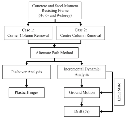
Xueet al. (2008). Figure 1 shows the flowchart
methodology.
A. Material properties and loading
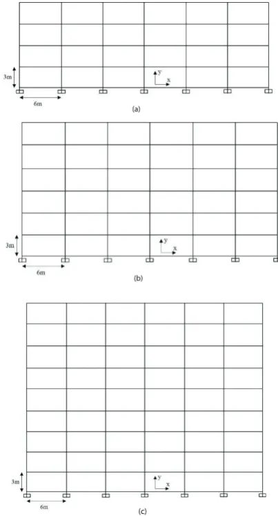
In this study, three buildings of different sizes
(4-, 6-, and 9-storeys) were investigated. The
height of each storey was 3.0m with a bay width
of 6.0m and slab thickness of 15cm. As shown
in Figure 2 (a), 2 (b), and 2 (c). The structure
had no irregularities in its elevation.
The Moment Resisting Concrete Frames were
designed based on Eurocode, and the designed
Concrete and Steel Moment Resisting Frame (4-, 6- and 9-storey)
Case 1: Corner Column Removal
Case 2: Centre Column Removal
Alternate Path Method
Pushover Analysis Incremental Dynamic Analysis
Plastic Hinges Ground Motion
Drift (%) L im it S ta te
Figure 1. Flow Chart Methodology
ground acceleration is assumed to be 0.5g of
ground type A which refers to rocks in a
geo-logical formation. The gravity loads consisting
of dead loads (Gk) and live loads (Qk) were
ap-plied to all floors which were taken as 5.3kN/m2, and 4kN/m2 respectively. Table 1 illustrates the structural modelling data input for analysing
MRCF and MRSF. The column size selected
measured 500mm x 500mm, whereas the beam
size measured 300mm x 700mm with a
compres-sive strength of 30MPa. Based on the frame
design, the columns and beams were reinforced
with T20 bars and T10 link reinforcement with
a yield stress of 460N/mm2.
For Moment-Resisting Steel Frames (MRSF),
the design followed EC3 and associated with
EC8, the steel grade was assumed as S275 for
the steel frame structure. Based on the
uni-versal columns (UC) and beams (UB) standard
sections that refer to the specifications of the
H-shape, the column section sizes used were
305mm x 305mm x 198mm for 4- and 6-storey
9-storey buildings. For beams, the selected
di-mensions were 533mm x 210mm x 92mm for
4-and 6-storey buildings 4-and UB533mm x 210mm
x 101mm for 9-storey buildings. Table 2 and 3
illustrate the section properties for MRCF and
MRSF respectively.
(a)
(b)
(c)
Figure 2. Moment resisting frame (MRF)
elevation view (a) 4-storey frame; (b) 6-storey
frame; and (c) 9-storey frame
III. ANALYSING AND MODELLING THE PROGRESSIVE COLLAPSE
The potential for progressive collapse of these
buildings is due to the removal of columns based
on the Alternative Path Method (APM). Two
cases of column removal were applied in the
anal-ysis. Case 1 referred to the removal of corner
columns while Case 2 referred to the removal of
centre columns of buildings as shown in Figure
3 (a) and (b). Both cases demonstrated the
re-moval of columns at ground floor level. In this
paper, the analyses were done using pushover
analysis (POA) and incremental dynamic
analy-sis (IDA). Therefore, the mentioned procedure
has been applied for analysing the structure
for three different storey heights. According to
Unified Facilities Criteria (UFC) guidelines, the
following load combinations; equation (1) and
equation (2) have been applied to the entire
structure.
For non-linear static analysis (POA):
2(Gk+ 0.25Qk) (1)
(Gk+ 0.25Qk) (2)
A. Plastic Hinges and Drift limits
Pushover analysis and incremental dynamic
analysis were conducted after column removal.
The increase in load due to column removal will
cause excessive load to the residual structure.
Plastic hinges are formed and the drift values
increase as the load increases. The value of the
plastic rotations at the plastic hinges will be
Table 1. Structural modelling data input for MRCF and MRSF
Input structural data analysis parameters
Slab thickness 15cm
Bay width 6m
Storey height 3m
Dead load (Gk) 5.3kPa
Live load (Qk) 4kPa
Ground Type A
Design ground acceleration on type A ground = .
Important factor ( ) 1.0
Peak ground acceleration ( ) 0.5g Type of analysis Nonlinear analysis
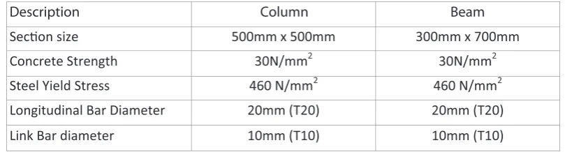
Table 2. Section properties of Moment Resisting Concrete Frame (MRCF)
Description Column Beam
Secon size 500mm x 500mm 300mm x 700mm
Concrete Strength 30N/mm2 30N/mm2
Steel Yield Stress 460 N/mm2 460 N/mm2
Longitudinal Bar Diameter 20mm (T20) 20mm (T20)
Link Bar diameter 10mm (T10) 10mm (T10)
Meanwhile, the % drift after performing the IDA
analysis will be compared with the drift limit
suggested by FEMA-273 and Xue et al. (2008).
The recommended limit states are OP, IO, LS,
DC, and CP at % drift equivalent to 0.5%, 1%,
1.5%, 2%, and 2.5% respectively.
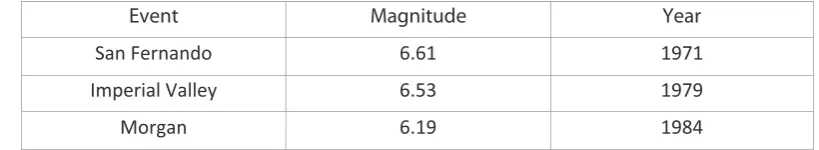
B. Ground motion records
IDA analyses require a suitable set of ground
motion records. According to Nazri (2011),
a few parameters to consider during the
se-lection of ground motion are event magnitude,
peak ground acceleration (PGA), distance, and
soil type. Ground motion time-histories
recom-mend a minimum of three sets of ground
mo-tion records as stated in FEMA 450. Thus, for
this study, three sets of ground motion records
were used. Smerziniet al. (2014) suggested that
the range of magnitude to be considered should
be between 5.0 to 7.3. Table 4 represents the
selected ground motion events from the PEER
NGA website.
IV. RESULTS AND DISCUSSION
A. Pushover analysis
Pushover analyses performed consisted of two
load cases applied to the structure. Gravity
loads and lateral loads were applied over the
height of the structure. The gravity load on the
members is a combination of Dead Load (DL)
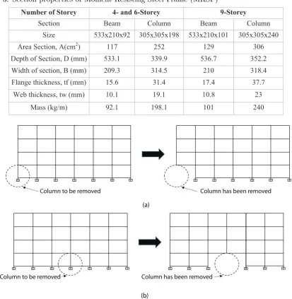
distribu-Table 3. Section properties of Moment Resisting Steel Frame (MRSF)
Number of Storey 4- and 6-Storey 9-Storey
Section Beam Column Beam Column
Size 533x210x92 305x305x198 533x210x101 305x305x240
Area Section, A(cm2) 117 252 129 306
Depth of Section, D (mm) 533.1 339.9 536.7 352.2
Width of section, B (mm) 209.3 314.5 210 318.4
Flange thickness, tf (mm) 15.6 31.4 17.4 37.7
Web thickness, tw (mm) 10.1 19.1 10.8 23
Mass (kg/m) 92.1 198.1 101 240
Column has been removed Column to be removed
(a)
(b)
Column to be removed Column has been removed
Figure 3. Removal of column (a) Case 1: Corner Column; (b) Case 2: Center Column
tion pattern for lateral loading used is triangular
distribution. Through the analysis, the pushover
curve of base shear versus displacement was
plot-ted.
There were 12 structures analysed using
Pushover Analysis (POA) including Moment
Re-sisting Concrete Frame (MRCF) for Case 1 and
Case 2, and Moment Resisting Steel Frame
(MRSF) for Case 1 and Case 2 with three
dif-ferent storey heights. The base shear demands
from these analyses were compared.
Based on the pushover curves in Figure 4(a)
and 4(b), the base shear values of 4-, 6-, and
9-storey MRCF structures and 4-, 6-, and 9-9-storey
MRSF structures computed from the
analy-sis were 1919.89kN, 1875.16kN, and 1553.97kN,
4523.59kN, 3987.78kN and 3728.58kN,
Table 4. Selection of Ground Motion
Event Magnitude Year
San Fernando 6.61 1971
Imperial Valley 6.53 1979
Morgan 6.19 1984
base shear value was obtained by the 4-storey
MRSF structure. The highest base shear value
obtained was 4523.59kN. Meanwhile, 9-storey
MRCF structure carried the lowest value of base
shear is 1553.97kN.
For Case 2, the base shear values of 4-, 6-,
and 9-storey MRCF structures and 4-, 6-, and
9-storey MRSF structures computed from the
analysis were 1374.56kN, 1189.33kN, 978.03kN,
and 4550.27kN, 4056.09kN and 3847.86kN,
re-spectively. The same scenario occurred for Case
2 where the highest base shear value obtained
was obtained by the 4-storey MRSF structure
(4550.27kN) while the lowest value was obtained
by the 9-storey MRCF structure (978.03kN).
The result showed that MRSF has the ability
to carry a higher value of shear force compared to
MRCF. This is due to the higher moment
capac-ity possessed by MRSF compared to MRCF. In
the case of column removal, the base shear value
of 4-storey structures is greater than that of
6-and 9-storey structures. This is explained by the
fact that the weight of structural elements due to
column removal is transferred to other elements.
Therefore, this situation leads to an increase in
structural pressure.
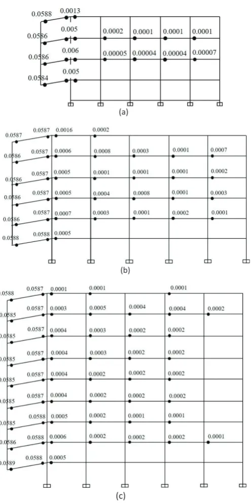
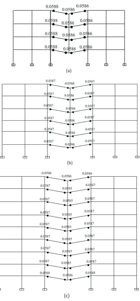
B. Plastic Hinges
As a result of the pushover analysis, the
for-mation of hinges can be viewed graphically on a
step-by-step basis. Figure 5 and Figure 6 show
the distribution of plastic hinges for
Moment-Resisting Concrete Frame (MRCF) Structure for
Case 1 and Case 2. The results presented in
the figures show the value of plastic rotation of
each hinge formed. As shown, most of the
val-ues are larger than the limit value recommended
by FEMA (0.05 rad). Therefore, structure
fail-ure is represented by the occurrence of plastic
hinges at the end of the beams. This
instabil-ity of the structure system enhances the collapse
mechanism.
However, for the Moment Resisting Steel
Frame (MRSF), the sudden removal of the
col-umn at the first floor causes the downward
dis-placement at the point in different storeys above
the removed column as shown in Figure 5 and
Figure 6. Moreover, no plastic hinges formed in
MRSF due to the removal of a single column.
Based on the results, it can be concluded that
the Moment Resisting Steel Frame (MRSF) will
not suffer progressive collapse as it successfully
absorbed the loss of the first-floor column which
was due to the removal of a single column (either
corner or centre column). Therefore, MRSF is
more sustainable in resisting single column loss
compared to MRCF which has a larger potential
(a) Case 1: (Corner Column)
(a) Case 1: (Center Column)
Figure 4. Pushover Curve of MRCF and MRSF
C. Incremental Dynamic Analysis (IDA)
It is very important to determine whether
structure due to column loss has adequate
dura-bility by referring to the drift limit state. In this
study, two schemes (Case 1 and Case 2) of IDA
analysis were considered. Only MRCF was
ap-plied in this analysis due to a higher potential
for progressive collapse.
(a)
(b)
(c)
Figure 5. Distribution of Plastic Hinges of Moment-Resisting Concrete Frame (MRCF) for the
Removal of Corner Columns in (a), (b) and (c), Case 1
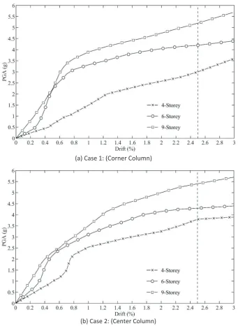
IDA curves in Figure 7(a) and Figure 7(b), the
incremental dynamic analysis (IDA) shows that
the total height of the structure can influence
the potential of the structure to collapse. In
the first case (Case 1), the element removed at
the corner of the structure showed that the
4-storey MRCF structure reaches the collapse
pre-vention limit state (CP) at peak ground
acceler-ation (PGA) of 3g. This was followed by PGA
(a)
(b)
(c)
Figure 6. Distribution of Plastic Hinges of Moment-Resisting Concrete Frame (MRCF) for the
Removal of Center Columns in (a), (b) and (c), Case 2
buildings respectively. For the second case (Case
2), the element removed at the centre of the
structure showed that the 4-storey MRCF
struc-ture reaches the collapse prevention limit state
at a PGA of 3.8g, followed by PGA values of
4.3g and 5.4g for 6-storey and 9-storey
build-ings respectively. Therefore, it can be concluded
shak-ing due to higher PGA. Moreover, the
poten-tial for progressive collapse reduces as the
num-ber of storeys increases. This result is in
agree-ment with a previous study done by Kandil et
al. (2013) where it was found that the potential
of progressive collapse reduces as the number of
storeys increases because of structural members
which resist progressive collapse behaviour. In
addition, from the analysis, structures which lose
a centre column was found to be more
sustain-able compared to structures which lose a corner
column as corner column loss leads to a higher
tendency of progressive collapse.
V. CONCLUSION
This study investigates the behaviour of
Moment-Resisting Concrete Frame (MRCF) and
Moment-Resisting Steel Frame (MRSF) towards
progressive collapse. This study emphasises the
elimination of external structural columns in two
different locations. In the first case, the
col-umn at the corner of a structure is removed.
For the second case, the column at the
cen-tre of the structure is removed. SAP 2000 was
used to analyse both cases using Pushover
Anal-ysis (POA) and Incremental Dynamic AnalAnal-ysis
(IDA).
Based on the results, the following
conclu-sions can be made:
1. Based on the Pushover Analysis (POA),
MRSF was found to be more resistant
to-wards damage or failure due to a smaller
displacement induced to the structure
when a larger shear force is applied.
2. The highest value of plastic rotation
recorded (0.0589 rad) occurred in the
9-storey MRCF structure of Case 1 and
Case 2. MRCF has a larger potential
of experiencing progressive collapse than
MRSF.
3. Higher buildings are better able to resist
shaking due to higher Peak Ground
Ac-celeration (PGA). Moreover, the
poten-tial for progressive collapse reduces as the
number of storeys increases.
4. The critical condition of corner column
removed from the structure is observed.
Therefore, the removal of corner columns
increases the potential for progressive
col-lapse compared to the removal of centre
(a) Case 1: (Corner Column)
(b) Case 2: (Center Column)
Figure 7. Mean IDA curves of (a): Case 1, and (b): Case 2
VI. ACKNOWLEDGMENTS
This research was supported by the
Univer-siti Sains Malaysia under the Short Term Grant
Scheme (60313036).
VII. REFERENCES
[1] Al-Salloum, Y., Almusallam, T., Ngo, T., El-sanadedy, H., Abbas, H. and Mendis, P. (2016)
Medium-Rise Circular RC Building Against Blast Loads. ASME 2016 35th International Conference
on Ocean, Offshore and Arctic Engineering. American Society of Mechanical Engineers, V009T12A005-V009T12A005.
[2] Alrudaini, T. M. S. and Hadi, M. N. (2010)
A new design to prevent progressive collapse
of reinforced concrete buildings. The 5th Civil Engineering Conference in the Asian Region and Australasian Structural Engineering Con-ference.
[3] Asgarian, B. and Hashemi Rezvani, F. (2010)
Determination of progressive collapse-impact
factor of concentric braced frames. Proceedings of the 14thEuropean conference on earthquake
engineering, Ohrid, Republic of Macedonia. [4] Chidambaram, C., Shah, J., Kumar, A. S. and
Karthikeyan, K. (2016) A Study on Progressive Collapse Behavior of Steel Structures Subjected to Fire Loads. Indian Journal of Science and Technology, 9.
[5] CSI. (2004) SAP 2000 integrated finite element analysis and design of structures. v10ed. Com-puter and Structures Inc, Berkeley.
[6] Dinar, Y., Alam, M. and Paul, S. (2013) Perfor-mance Based Analysis of RC building consisting Shear wall and varying infill percentage. Euro-pean Academic Research, 1, pp. 2927-2947. [7] Dod, U. (2005) UFC 4-023-03.Design of
Build-ing to Resist Progressive Collapse. Unified Fa-cility Criteria, United States Department of De-fense, Washington, DC.
[8] Elshaer, A., Mostafa, H. and Salem, H. (2017) Progressive collapse assessment of multistory re-inforced concrete structures subjected to seismic actions. KSCEJournal of Civil Engineering, 21, pp. 184-194.
[9] Feng, P., Qiang, H., Qin, W. and Gao, M. (2017) A novel kinked rebar configuration for simul-taneously improving the seismic performance and progressive collapse resistance of RC frame structures.Engineering Structures, 147, pp. 752-767.
[10] Gerasimidis, S., Deodatis, G., Kontoroupi, T. and Ettouney, M. (2015) Loss-of-stability in-duced progressive collapse modes in 3D steel moment frames. Structure and Infrastructure Engineering, 11, pp. 334-344.
[11] Goel, M., Agrawal, D. and Choubey, A. (2017) Collapse Behavior of RCC Building under Blast Load.Procedia Engineering, 173, pp. 1943-1950. [12] Gsa, U. (2003)Progressive collapse analysis and design guidelines for new federal office buildings
and major modernization projects. Washington, DC.
[13] Hadi, M. N. and Saeed Alrudaini, T. M. (2012) New building scheme to resist progressive col-lapse.Journal of Architectural Engineering, 18, pp. 324-331.
[14] Hosseini, M., Fanaie, N. and Yousefi, A. M. (2014) Studying the vulnerability of steel mo-ment resistant frames subjected to progressive collapse. Indian Journal of Science and Tech-nology, 7, pp. 335.
[15] Jalalilarijani, R., Celikag, M., Aghayan, I. and Kazemi, M. (2013) Progressive collapse analy-sis of two existing steel buildings using a lin-ear static procedure.Structural engineering and Mechanics, 48, pp. 207-220.
[16] Kandil, K. S., Ellobody, E. A. E. F. and El-dehemy, H. (2013) Progressive collapse of steel frames.World Journal of Engineering and Tech-nology, 1, pp. 39.
[17] Kyei, C. and Braimah, A. (2017) Effects of transverse reinforcement spacing on the re-sponse of reinforced concrete columns subjected to blast loading. Engineering Structures, 142, pp. 148-164.
[18] Lu, D.-G., Cui, S.-S., Song, P.-Y. and Chen, Z.-H. (2011) Robustness assessment for progressive collapse of framed structures using pushdown analysis methods. International Journal of Re-liability and Safety, 6, pp. 15-37.
[20] Rakshith, K. G. and Radhakrishna (2013) Pro-gressive Collapse Analysis Of Reinforced Con-crete Framed Structure. International Journal of Research in Engineering and Technology, IC-RICE Conference Issue, pp. 36-40.
[21] Rezvani, F. H., Taghizadeh, M. A. M. and Ron-agh, H. R. (2017) Effect of inverted-V bracing on retrofitting against progressive collapse of steel moment resisting frames. International Journal of Steel Structures, 17, pp. 1103-1113.
[22] Sideri, J., Mullen, C. L., Gerasimidis, S. and Deodatis, G. (2017) Distributed Column Dam-age Effect on Progressive Collapse Vulnerability in Steel Buildings Exposed to an External Blast Event. Journal of Performance of Constructed Facilities, 31, 04017077.
[23] Smerzini, C., Galasso, C., Iervolino, I. & Paolucci, R. (2014) Ground motion record selec-tion based on broadband spectral compatibility.
Earthquake Spectra, 30, pp. 1427-1448.
[24] Tavakoli, H. and Alashti, A. R. (2013) Evalu-ation of progressive collapse potential of multi-story moment resisting steel frame buildings un-der lateral loading. Scientia Iranica, 20, pp. 77-86.
[25] Wang, H., Zhang, A., Li, Y. and Yan, W. (2014) A review on progressive collapse of building structures. Open Civil Engineering Journal, 8, pp. 183-192.
[26] Xue, Q., Wu, C.-W., Chen, C.-C. and Chen, K.-C. (2008) The draft code for performance-based seismic design of buildings in Taiwan. Engineer-ing Structures, 30, pp. 1535-1547.