AN IMPROVED ARCHITECTURE FOR
MINIMIZING REAL TIME PACKET
LOSS IN MIPV6
DR. SAPNA GAMBHIRYMCA University of Science & Technology, Faridabad, Haryana, India
SHILPY GUPTA Research Scholar,
YMCA University of Science & Technology, Faridabad, Haryana, India
Abstract :
With the advent of mobile devices, the internet now undertook a huge and unexpected explosion of growth. The wireless mobile internet gives users access to the internet services while they are on move. This mobility has been supported through the Internet Protocol known as Mobile IP (MIP). MIP allows users with mobile devices to have continuous network connectivity to the internet without changing their IP addresses when moving from one network to another. While on move, Mobile Node (MN) undergoes a handover process, in which the MN gets disconnected from one Point of Attachment (PoA) and tries to connect to another PoA.
Keywords: MIPv6, Handover Latency, Care-of-Address, Duplicate Address Detection.
1. Introduction
The various technological advancements, like the advent of PDAs and laptops, lead to rise in demand for mobile communications. The wireless mobile internet is an extension of the internet into the mobile environment, which gives users access to the internet services while they are on move [1]. Mobile communication has received a lot of attention in the last decades. The interest in mobile communication on the internet means that IP protocol, originally designed for stationary devices, must be enhanced to allow the use of mobile devices [2]. The mobile users want to have indefinite access to the network in fixed IP with their portable devices, beyond the limits of time and place. However, since basic IP has some limitations to provide mobility, users have to change IP address according to the access points. Thus, there emerges the necessity of Mobile IP (MIP). In MIP, when a MN moves away from one PoA and attaches to another, it needs to obtain a new IP address. This procedure is known as the handover [3]. The handover process can be defined as a sequence of steps that are performed when a MN gets disconnected from one network and tries to connect to another network. Handover mechanism is the important part of Mobile IP. The handover process involves various steps, viz, discovery of routers, movement detection, care-of-address configuration, duplicate-address-detection and binding registration. The handover in MIPv6 with basic steps is shown in Fig. 1.
Fig.. 1. Handover in MIP
When the MN moves from one network to another, the MN requires to get new IP address and register this new address with the HA and the CNs to get connected. This may take a substantial period of time that may not be suitable for the real-time applications
Also during the handover, the MN cannot receive packets that the CN sent to it. This may lead to the packet loss.
These latency and packet loss problems remains until the MN gets new address from the new network and register its binding with the HA as well as the CN. In real-time traffic, this situation will be a huge setback for which a new architecture is proposed to overcome these problems. Numerous efforts have been attempted to develop efficient handover schemes. To minimize real time packet loss, an improved architecture is proposed in this paper.
The paper is organized as follows: The basic MIPv6 architecture is reviewed in Section II. Section III provides details of the improved architecture. Then, Section IV evaluates the improved architecture on the basis of numerical analysis followed by the comparison of basic MIPv6 architecture and the Improved MIPv6 architecture in Section V. Lastly; conclusion is given in Section VI.
2. Basic MIPv6 Architecture
The MIPv6 handover is composed of L2-handover and L3-handover where L2 handover is the process by which the MN changes from one link-layer connection to another. L3 handover is the process in which a MN detects a change in an on-link network prefix that would require a change in the primary CoA [5]. The L2 handover latency is negligible as compared to the L3 handover latency. Thus L3 handover latency is the major problem that is of greater concern. This L3 handover process is illustrated in Fig. 2 [6]. The L3 handover process consists of five phases:
1) Discovery of Routers
The MN uses the “Neighbor Discovery” protocol mechanisms to detect the available neighboring routers. In this mechanism, the routers send Router Advertisement (RA) messages periodically, or in response to Router Solicitation (RS) message from MN [7].
2) Movement Detection
3) Care-of-Address Configuration
When MN finds that it has no more contact with its current router, it chooses another one in its default router list and creates its IP address starting from the corresponding prefix, using stateless address autoconfiguration [3].
Fig.. 2. Basic MIPv6
4) Duplicate-Address-Detection
Once an IPv6 MN has configured its CoA, it must perform DAD to ensure that its configured address is unique on the link. Until the DAD is performed successfully, the configured CoA is considered as tentative. To perform DAD, MN sends Neighbor Solicitation (NS) message with its own address as the target address of the solicitation message. The destination address in the IPv6 header of the NS is set to the solicited node multicast address of the target address with the source address being the unspecified address [3]. If there is another node on the link that is using the same address as the tentative CoA, that node will acknowledge the message by sending the Neighbor Advertisement (NA) message to the MN. If the MN receives the NA message, the tentative CoA is not unique. Then, the MN re-configures the CoA and repeats the process until it gets a unique CoA. When it detects a CoA that is unique, the address is assigned to the MN [8].
5) Binding Registration
delay in communication,
lesser throughput (average rate of successful data delivery over a communication channel) [10],
Packet loss (number of packets that doesn’t reach their destination).
These problems will be huge during real time sessions between the MN and CN. The major issue needs to be resolved is the packet loss. To minimize the packet loss, an improved MIPv6 architecture is proposed as discussed in the next Section.
3. Improved MIPv6 Architecture
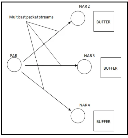
The proposed architecture suggests the solution to the problem of packet loss that occurs in the existing MIPv6. Proposed architecture suggests the use of the buffering mechanism to minimize the packet loss. Proposed architecture suggests the multicasting of packets, during handover, from the PAR to the NAR where these packets will be buffered. After the completion of the handover process, these packets will be forwarded to the intended MN. This solution minimizes the packet loss. This solution is explained as follows.
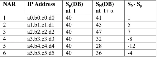
NARs will be selected from the available routers neighboring PAR as shown in Fig. 3. When MN receives RA messages from the neighboring routers after every α seconds as shown in Fig. 4, it checks for the signal strength and maintains its information in a table as shown in Table 1.
Fig. 3. Neighboring Routers
Fig. 4. Position of the MN when receiving the RAs
of the six neighboring routers and their previous and new signal strengths. The memory size depends on the size of NAR’s address, and the size required storing the values of signal strengths for six neighboring routers. When a message or signal is received from the nearby device, the signal strength is more than that received from the far away device. So if the signal strength of the received RAs is increasing, this means that the MN is moving towards the source router. If the signal strength of the received RAs is decreasing, this means that MN is moving away from the source router.
Table 1. Data Structure storing information about the Signals
The neighboring routers, whose RA message’s signal strength is increasing, are considered to be the possible NARs to which the MN can precede during handover process. So these will be selected, their addresses are grouped as the multicast group addresses. On predicting a handover to a NAR, the MN submits this multicast group addresses to PAR by encapsulating as Mobility Options in Fast Binding Update (FBU) message. Then the PAR retrieves this multicast group of addresses from the FBU, and performs the multicasting of the packets sent by the CN during handover, to the multicast group addresses. Considering the routers NAR2, NAR 3 and NAR4 be the possible NARs to which MN can proceed for handover, this forwarding of packets can be done as shown in Fig. 5.
Fig. 5.Buffering of Multicast Packet Stream
These packets are then buffered at all these NARs for t seconds, where t would be selected as: t > THandover
THandover is the time required for handover process. Thus, THandover would act as the threshold value for buffering, before which the packets would be lost. When the MN completes its handover with any of these routers, that NAR will forward these buffered packets to the MN. After forwarding the packets, these will be discarded at the NAR
4. Numerical Analysis
Packet loss is the number of packets that are lost during the handover process. In general, in wireless and mobile networks, packet loss is mostly caused by bit errors in an error-prone wireless channel, congestion in the network, or due to handover. The main reason for packet loss caused by handover is the fact that packets are
routed to the PAR for buffering while the link to the PAR is already broken. These packets might be dropped by the PAR. Thus in the existing architecture for MIPv6, there is a great possibility of packet loss during handover after the disconnection of the MN from the previous network. While in the proposed architecture, as we suggest the buffering of packets for the time interval greater than the threshold value which is equal to the value of handover latency, the problem of real-time packet loss due to handover latency will be resolved completely. Thus,
Buffering time, TBUFFERING > THANDOVER_ImprovedMIPv6,
As an example, consider Fig. 6 where MN is receiving RA from all it’s six neighbors. Suppose the MN is moving in the direction as shown in Fig. 6. Signal strength received by MN at time t when MN is at the centre of middle cell and at time t+ α. Details of the signal strength is shown in Table 2.
Fig. 6. Direction of Movement of MN
Table 2. Sample s Data Set for Storing information of the Signals
From the table, it is clear that MN is moving closer to NAR1, NAR2 and NAR3 rather than remaining ones. So, it is feasible to multicast the packets to these NARs during handover process rather than multicasting it to all other NARs. This reduces the network overhead and removes the problem of packet loss during handover. Still there are some situations when the packet loss is possible, which is very less as compared to that in existing architecture. These situations are:
a) Due to bit errors in an error-prone wireless channel b) Congestion in the network
c) When MN moves towards the black hole region or gets disconnected for more than the packet buffering time NAR IP Address Sp(DB)
at t
SN(DB)
at t+ α SN- Sp
1 a0.b0.c0.d0 40 41 1
2 a1.b1.c1.d1 40 45 5
3 a2.b2.c2.d2 40 47 7
4 a3.b3.c3.d3 40 32 -8
5 a4.b4.c4.d4 40 28 -12
6 a5.b5.c5.d5 40 36 -4
MN NAR6
NAR4
NAR5 NAR1
NAR3
NAR2 Direction of Movement t
Conclusion
With the proposal of improved MIPv6 architecture, it is concluded that the problems of packet loss that occurs in existing MIPv6 would be resolved to a great extent providing an efficient and reliable mobility in MIPv6. At a little cost for the memory management and the router updation, the mobility in IPv6 could achieve the goals of minimized real-time packet loss.
References
[1] Jamalipour, “The Wireless Mobile Internet Architecture, Protocols and Services”, Wiley, 2002. [2] B.A. Forouzan, “TCP/IP Protocol Suite”, 3rd Ed., Tata McGraw Hill, 2006.
[3] M. Dunmore, T. Pagtzis, and C. Edwards, “Mobile IPv6 Handovers: Performance Analysis and Evaluation”, IST-2001-32603. [4] http://www.6net.org/publications/deliverables/D4.1.3v2.pdf, 2005.
[5] D.P. Kim, and S.J. Koh, “Analysis of Handover Latency for Mobile IPv6 and mSCTP”, Journal of Information Processing Systems, vol.4, no.3, pp. 87–96, 2008.
[6] D. Johnson, C. Perkins, and J. Arkko, “Mobility Support in IPv6”, RFC 3775, Network Working Group, 2004.
[7] J.C. Murillo, J.L.G. Sanchez, and I.G. Robledo, “Handover Performance Analysis in Mobile IPv6, A Contribution to Fast Movement Detection”, International Conference on Wireless Information Networks and Systems, WINSYS, pp. 78-81, 2008.
[8] T. Narten, E. Nordmark, and W. Simpson, “Neighbor Discovery for IP Version 6 (IPv6)”, RFC 2461, Network Working Group, 1998. [9] S. Thomson, T. Narten, and T. Jinmei, “IPv6 Stateless Address Autoconfiguration”, RFC 2862, Network Working Group, 2007. [10] S. Mahmood, “Triangle Routing in Mobile IP”.
[11] http://suraj.lums.edu.pk/~cs678s04/2004%20Projects/Finals/Group04.pdf.