CRYOGENIC PROCESSES – A REVIEW
RADHEY SHAM
Associate Professor, MED, CEC Landran, Mohali 140307. India.
T K JINDAL
Assistant Professor, AED, PEC University of Technology, sector 12, Chandigarh 160012, India.
B S PABLA
Professor, MED, NITTR, Sector 26, Chandigarh 160026, India.
Abstract
Cryogenics deals with the production and maintaining temperatures below -1500C. Cryogenic processes include
liquefaction of air, oxygen, nitrogen, hydrogen and helium. Final liquefaction is obtainable only if the temperature before throttling is below inversion temperature. Hydrogen and helium have their inversion temperatures as -77.80C and -2500C respectively. Extremely low temperatures are obtained by the
demagnetization of a paramagnetic salt. Cryogenic temperatures are useful for storage of large volumes of gases in small space in the liquefied form, preservation of insemination, very high vacuum applications and fundamental research in understanding more deeply thermodynamic concepts and also sub-atomic structure of matter as the motion of protons, electrons significantly reduces at cryogenic temperatures. Ductile metals and alloys maintain their ductility and also acquire superconductivity at low temperatures.
Key words: cryogenics, liquifaction, magnetic cooling, inversion temperature.
Introduction
Cryogenics is that branch of engineering which deals with temperatures lower than -1500C. There are many
areas of interest where we need cryogenic temperatures such as storage of large volumes of gases in small space in the liquefied form, preservation of insemination, very high vacuum applications and fundamental research in understanding more deeply about entropy and sub-atomic structure of matter as the motion of protons, electrons reduces at cryogenic temperatures.
2. Cryogenic Methods and their analysis (a) Liquefaction of gases
In order to liquefy a gas, one or two types of gas expansions are employed. These are
(i) Isotropic expansion/real expansion
This type of expansion is a reversible expansion and is used for partial cooling of gases leading to their subsequent liquefaction. By this process alone, liquefaction is not feasible because of lubrication and erosion problems.Under this process, the temperature after expansion is given by the relation given below:
For an (isentropic) Theoretical process
(T2/T1)= (p2/p1)(--1)/
For a real process
(T2/T1)= (p2/p1)(n--1)/n
Where n=1 to but <
(ii) Throttling expansion
Throttling expansion of a gas eliminates the lubrication difficulties, simplifies the equipment necessary but does so with a marked lowering of the efficiency (Complete loss from high pressure to low pressure as no work is recovered). But to attain the liquefaction and to overcome the practical difficulties associated with the reversible expansion, throttling is the must process for the liquefaction of each gas. It is also called as Joule Thomson Expansion.
Joule Thomson coefficient= μ = (T/p) h=C
Joule Thomson Coefficient is a function of both temperature and pressure. Therefore it does not have a unique value.
3. Inversion temperature:
Maximum temperature at which Joule Thomson coefficient μ = (T/p) h=C is zero. It represents neither heating
nor cooling on expansion which is possible only for an ideal gas. There is only one (maximum) inversion temperature for an ideal gas. The Inversion temperature for real gases is not unique as it is a function of both temperature and pressure and thus there is one maximum inversion temperature for each gas. If the temperature of the gas is above the inversion temperature before expansion, then heating occurs upon expansion. If temperature is below the inversion temperature before expansion, cooling results on expansion. Consequently whenever a gas has to undergo cooling upon expansion, it must be at a temperature below its inversion temperature. For such a case fall of temperature with fall of pressure makes the Joule Thomson Coefficient positive. Final liquefaction is practically possible only with throttling process. The maximum inversion temperature of various gases is given below:
TABLE 1: IMPORTANT PROPERTIES OF GASES
Gas N.B.P. 0 C Freezing Point 0 C Critical Temperature 0 C
Maximum inversion Temp. 0
C
Air -191 -212.3 -140.2 330
O2 -183 -218.8 -118.8 620
N2 -196 -210 -147.0 347.8
H2 -252.8 -259.2 -239.9 -77.8
He -268.9 -269.7 -267.9 -250.0
CO2 -78.3 --- 31.1 1230
It is important to note that the inversion temperatures of hydrogen and helium are -77.80C and -2500C. Therefore
these gases are to be brought below the inversion temperatures before throttling to achieve liquefaction.
4. Advantages of Liquefaction
1. Liquefaction of gases produces cryogenic temperatures required for fundamental research. 2. Liquefaction helps in storing large volume of gases in small storages.
TABLE 2: REDUCTION IN VOLUME ON LIQUEFACTION
Gas Wt. Volume on liquefaction
Volume of gas
Reduction ratio
O2 1 0.031 26.62 858
N2 1 0.044 30.41 691
Air 1 0.040 29.50 737
H2 1 0.496 422.41 851.6
He 1 0.282 213.4 756.7
Liquefaction of gases is achieved by employing.
a. Joule Thomson expansion alone or
b. isentropic expansion as well as Joule Thomson expansion
Liquefaction of air
a) Linde’s process b) Claude’s process
a) Linde’s (or Hampson) air liquefaction method
Principle – Uses only Joule Thomson expansion for liquefaction
In Linde’s process (Fig.1 (a) and (b)), the air is compressed to 200 atm and the yield is about 10 percent. Oxygen and nitrogen are obtained by fractional distillation of liquid air.
Analysis: - Basis – for a unit weight of air liquefaction
t1 = t 2 = t7
p1 = p7 =1 atm
p2 = 200 atm
Mass balance
m4 = m6+1 = m7+1 (i)
m1 = m2 = m3 = m4
m6 = m7
m5 = 1
Energy balance around heat exchanger.
Energy entering = energy leaving
m2h2+m6h6 = m3h3+m7h7 (ii)
h2, h6, h7 are known from T-S chart for air and unknowns are m2 and h3.
Energy balance around separator
Energy entering = energy leaving
m4 h4 = m5 h5 + m6 h6 (iii)
But h4 = h3 (iv)
m4 & h3 are unknown and are solved by using equations (i), (ii), (iii) & (iv).
Disadvantage of Linde’s air liquefaction method
(i) It results in a lower yield of around 10%.
(ii) The working pressure is very high resulting in high power consumption and requiring robust equipment.
Advantage: It is a simple method.
b) Claude’s air liquefaction method
Principle – uses both isentropic and throttling expansions
is passed through the second heat exchanger and then throttled to atmospheric pressure. The second stream with 80% going to the turbine and cooled on expansion. This cooled air from the turbine cools the air in heat exchanger II and thus lowers the temperature before throttling. This gives a higher percentage of liquefied air.
Analysis of Claude’s air liquefaction method
Basis: for a unit mass of air liquefaction
t1, t2, t11, t3 are known
h1, h2, h11, h3 are known
h3=h3’=h3”
t3=t3’=t3”
Apply energy balance around H.E.I., HE II & Separator
m2 h2 + m8 h8 = m8 h3 + (m2-1) h1 + 1.h6
In this process, yield is increased significantly as compared to Linde’s process. However some lubrication difficulties are encountered in expander.. but are overcome.
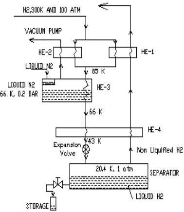
6. Liquefaction of Hydrogen
Peculiarity of Hydrogen: Ordinary hydrogen is simplest of atoms as it consists of a proton in the centre and an electron moving in the orbit around the nucleus. Both proton and electron are also spinning on their axes as well. As such there are four different types of hydrogen atoms (A, B, C and D) (Refer Fig.3). Firstly atoms A and C combine to form ortho hydrogen molecule (protons spinning in same directions but electrons spinning in the opposite directions). Secondly the atom A and D combine to form Para molecule of hydrogen. In atoms A and D, the protons as well as electron are spinning in the opposite directions. Thus at room temperature, Hydrogen gas consists of two molecular varieties, Ortho-hydrogen 75% and Para-hydrogen 25%. This composition does not change even in freshly liquefied hydrogen. However, over the passage of time, ortho- form tends to change to Para form till the equilibrium is reached at 99% Para form. It is an extremely a slow process. This conversion process is highly exothermic and releases heat (1420 kJ/kg) of hydrogen. This tremendous heat evolution causes liquid hydrogen to boil. This is called boil off loss. This loss is reduced by employing catalysts like Cr2O3 or Al2
O3 which accelerates the conversion of ortho into Para even before complete liquefaction of hydrogen is
achieved and boil off loss is avoided. Thus Hydrogen is liquefied as described below.
(i) Pre-cooling of hydrogen by liquid nitrogen to a temperature below its inversion temperature of -780C.
(ii) Throttlingexpansion(Fig.4).
Yield in this process is around 25 %.
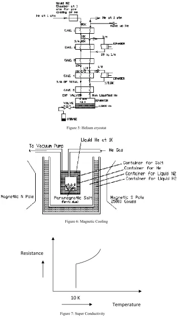
7. Helium Liquefaction byCollins’s Cryostat Principle
(i) Polytropic expansion for precooling
(iii) Throttling for liquefaction.
Liquefaction of helium (Fig.5) uses normal liquid nitrogen for precooling before the helium enters the first cascade heat exchanger. Since helium liquefies at a lower temperature than that of even hydrogen, more number of heat exchangers and other devices are incorporated in order to achieve significant amount of liquid helium with reasonable expenditure of energy. This liquefaction process requires about 45 KW to yield 35 to 40 liters of helium per hour.
Very Low temperatures of the order of 0.001 K have been obtained by demagnetization of a paramagnetic salt such as gadolinium-sulphate (Ferric Ammonium Alum, Fe2 (So4)(NH4)2So4 24 H2O). The salt is cooled to a
lower temperature of about 1 K by liquid helium at 0.2 atmospheric pressure. Now a strong magnetic field of 25000 Gauss intensity is applied, the molecules of the salt act as tiny magnets and arrange themselves in a regular arrangement and releases large amount of heat energy in doing so. The various steps for magnetic cooling (Fig.6) are as under:
Step 1 :
The paramagnetic salt is surrounded by boiling helium, at a low pressure (0.2 atm), which chills the salt to slightly below 1 K.
Step 2 :
A strong magnetic field is applied to the salt which aligns the molecules. In this process,
heat is released and the liquid helium removes the heat thus released and still maintains the salt at 1 K.
Step 3 :
The helium bath is removed and the salt is thermally insulated.
Step 4
Finally the magnetic field is removed. The molecules rearrange themselves and requires large amount of energy for this disorder. This energy is not available from anywhere. The salt gives out this energy from itself and thus plunges to extremely low temperatures reaching almost absolute zero.
9. Measurement of Cryogenic Temperatures
Constant volume gas thermometer is employed to measure the low temperatures. Such an instrument is based on Charles’s law stating that the pressure of a perfect gas varies directly with the absolute temperature if the volume is kept constant. Nitrogen is used for such instruments. Helium is used for very low temperatures because of its low liquefaction temperature.
10. Applications of Cryogenics a. Industrial applications:
Shrink fitting of metals
Liquid oxygen is used in welding, in the manufacture of steel
Liquid oxygen in artificial breathing in hospitals & aircrafts. For the preservation of blood, dead bodies and medicines.
For freezing the food for preservation - By spray of liquid nitrogen. Quick healing of wounds.
Cooling the body parts by anesthesia.
b. Agriculture:
Preservation of bull insemination for better creed. For the manufacture of cryogenic magnets
Super conductive transformers and Super conduction motors
Used in separation of gases i.e. air, Coke oven gas, Helium 3 from Helium 4 Economic transport of ice cream.
Superconductivity makes computers compact Liquid hydrogen is used as a fuel in rockets.
Spectrum lines are more sharpened at low temperatures.
Bolometers are used at low temperatures to measure very small quantity of radiant heat.
To understand thermodynamic concepts more deeply.
Cryo-pumps produces very high vacuum i.e. 10-12 mm of mercury.
Space research In Missile launching
11. Materials of Construction at Cryogenic Temperautres
FCC structure show no loss in ductility at low temperature while BCC and HCP structure show significant decrease in ductility at low temperatures and it is measured from the energy required to break the specimen.
TABLE 3: Change of ductility with low temperature
Metal Crystal lattice Energy to break (FT lb.)
at 700F Energy to break (FT lb.) at 3000 F
Al FCC 19 27
Cu FCC 43 50
Ni FCC 89 99
Iron BCC 78 1.5
Titanium HCP 14.5 6.6
Mg HCP 4 30-105
FCC structures are most suitable at cryogenic temperatures as these do not lose their ductility at low temperatures. Thus copper and its alloys, aluminum and its alloys are most suitable. Most metals show super-conductivity between temperatures of 4 to 15 K. Fig 7 shows the phenomenon of super-super-conductivity.
References:
[1] Mechanical properties of structural materials at low temps- NBS monograph 13, McClintock R.M. & gibbons, H.P., Washington
[2] Cryogenic materials data hand book- Durban, T.F., McClintock, R.M., Reed, and R.P.
[3] Scurlock, Ralph G., ed. (1993). History and Origins of Cryogenics. Oxford, Clarendon Press.
[4] Weisend, John G. II, ed. (1998). Handbook of Cryogenic Engineering. Philadelphia, Taylor and Francis
[5] Kinard, G.E., “ The Commercial use of Liquid Nitrogen Over the last 40 years”, International cryogenic Engineering Conference 17,
London 1998.
[6] A brief overview of cryogenics in China,S.M. Li, Cryogenic Laboratory, Zhejiang University, Hangzhou, 310027, China,2000
[7] Flynn, T.M., Cryogenic Engineering, Dekker, New York, 2005
FIGURES:
Figure 1(b): T-S Diagram of Linde’s Air Liquefaction Process.
Figure 2(a): Line Diagram of Claude’s Air Liquefaction Process.
Figure 3: Para and Ortho molecules of H2
Figure 5: Helium cryostat
Figure 6: Magnetic Cooling
Resistance
Temperature
10 K