Development and Validation of Task Instructional Sheet in Electrical Installation for Problem-Based Learning Environments in Technical Colleges
Prof. K.R.E. Okoye1 & 2Caleb, E. E. 1
Department of Technology and Vocational Education Nnamdi Azikiwe University, Awka, Nigeria
2
Department of Vocational Education University of Uyo, Uyo
Corresponding Author:[email protected]
Abstract
The study developed and validated a task instructional sheet in electrical installation and maintenance for assisting technical teachers seeking to implement problem-based learning in technical colleges. Instrumentation research design was employed in the study. The area of the study was South-South zone of Nigeria. The population of the study is 68 technical teachers with specialization in electrical installation and maintenance works in all the 20 public technical colleges in south-south, Nigeria. The entire 68 technical teachers were used in the study for the purpose of validating the electrical installation task instructional sheet. No sampling was done because the number was small and manageable. The instrument developed in this study is “Electrical Installation Task Instructional Sheet” (ESTIS). The instrument went through a multi validation process to establish the validity of the instrument. The reliability of the task instructional sheet was determined using a pilot test of 20 students from a school in the study population. A standard test of internal consistency of Cronbach Alpha was used for determining the reliability coefficient. This yielded a value of 0.84, indicating a high reliability index. The data generated was analysed using Mean, standard deviation to answer research the question while content validity of the process (psychomotor) component of the task instructional sheet was determined using Lawshe’s content validity index (CVI). Based on the findings of the study, it is concluded that the developed task instructional sheet in electrical installation and maintenance are valid and reliable to be used by technical teachers for implementing Problem-Based Learning environments in technical education programmes. It is recommended that Technical teachers should adopt the developed task instructional sheet and apply them in technical training institutions.
Keywords: PBL Environments, DACUM, tasks, task analysis, real world problems Introduction
Problem-based learning (PBL) is most often positioned as a student- or learner-centred
pedagogy, focusing on learners’ active and often collaborative creation of knowledge through
engaging with real-world problems. The PBL environment is a process and competency oriented
learning environment. The competency orientation component of PBL provides learners with the
skills, knowledge and attitudes to demonstrate proficiency against occupational standards and
PBL environment is also a student centred environment that influences greatly the
content and organization of instruction, educational process as well as the roles of students and
teachers. A teacher in a PBL environment is a coach, a trainer, a supervisor and an expert. A
student is no longer primarily focused on listening to the teacher, but has to accomplish tasks. A
teacher in PBL no longer offers and explains texts, but is offering experiences and tasks. Tasks
become an essential component of the PBL environment. Tasks according to Olaitan (2003) are a
set of logically related actions required for the completion of a job. Tasks are academic activities
that learners engage in, or carry out, using their existing knowledge and resources or those that
have been provided in pre-task work by the teacher. This takes on a whole new dimension when
teaching practical (psychomotor) aspects of technical education. Practical skill activities form a
major part of instruction in technical education as most activities in technical and vocational
education require practical skills to carry out. Problem-based learning (PBL) advocates that
learning environments should be replica work environments, thus, tasks as found in industries
and real life situations should be brought into the classroom for student learning. PBL further
advocates that support be offered to students to facilitate learning. One method the technical
teacher could use in class to facilitate learning during PBL tutorials is the use of task
instructional sheets.
Task instructional sheet is applied for training new job entrants or students. It lists the
steps of the job, detailing the systematic processes that may be required to perform the job safely
with utmost quality and efficiency. A task is any learning activity or assessment that asks
students to perform, to demonstrate their knowledge, understanding and proficiency.
Performance tasks yield a tangible product and/or performance that serve as evidence of
select from given alternatives, a performance task presents a situation that calls for learners to
apply their learning in context.
The use of teacher developed task instructional sheets in technical education is fast gaining
momentum and widely encouraged by academics.
In order to design instruction that will support learning, it is essential that designers
understand the nature of the tasks that learners will be performing. The principle is the same,
whether for direct instruction or for problem-based learning environments (Polson, 1993). The
development of a task instructional sheet begins with a task analysis of the occupation. A task
analysis is a systemic collection of data about a specific job or group of jobs to determine what
an employee should be taught and the resources he or she needs to achieve optimal performance
(DeSimone, Werner, Harris, 2002). The Task Analysis sequences and describes measurable
behaviours involved in the performance of a task. It also provides a detailed analysis of each task
in terms of frequency, difficulty and importance. The product is used for designing job
description, task inventory, performance systems, performance assessment system and training
design and development.
Task analysis in occupations and industrial technology can be performed using the
DACUM process. DACUM is an acronym for Developing A Curriculum. DACUM is widely applied in occupational analysis. Essentially, the DACUM process is a well-organized,
step-by-step brainstorming session that involves a panel of expert workers in the occupation being
analyzed and a qualified DACUM facilitator. In the DACUM process, expert workers in the
occupation are guided by a trained facilitator to identify the duties and tasks (competencies) of
the occupation, along with the supportive enablers such as knowledge and skills, tools and
The DACUM process is not complicated, but the development of a quality training
program entails additional steps. Once a DACUM profile is developed and reproduced on paper,
it should be validated by having other expert workers and supervisors review it for completeness
and accuracy. In job analysis, validity is the measure of the accuracy of a selection test or the
measure for predicting job performance. Validity is not inherent in any test but indicates how
appropriate the test is for a particular use. Validation of job analysis and selection procedures is
an essential task for instructional designers. In development and assessment of various kinds of
instructional packages, content-related validity is most appropriate (Jeffrey, 2001).
Content-related validity is the extent to which a selection method represents some portion
of the behaviours being assessed. Content validity depends on the extent to which an empirical
measurement reflects a specific domain of content. Content-related validity does not involve
correlation coefficients but is determined by subject matter experts (SMEs), who decide the
extent to which a predictor samples the domain of work behaviours. In this sense, content-related
measures involving specific knowledge and skills are interchangeable with the job tasks. Tests of
relevant job knowledge, proficiency tests, and work samples may be used as part of a
content-related validity study (Jeffrey, 2001).
The development of a content valid instrument is typically achieved by a rational analysis
of the instrument by raters (experts) familiar with the construct of interest or experts on the
research subject (Sangoseni, Hellman & Hill, 2013). Specifically, raters will review all of the
questionnaire items for readability, clarity and comprehensiveness and come to some level of
agreement as to which items should be included in the final questionnaire. Item rating and scale
level rating have been proposed for content validity. The item rated content validity indices
from I-CVI. S-CVI means the level of agreement between raters (Sangoseni, Hellman & Hill,
2013). Sangoseni et al.(2013), proposed a S-CVI of ≥0.78 as significant level for inclusion of an
item into the study.
Purpose of the Study
The purpose of the study is to develop and validate a task instructional sheet in electrical
installation for technical teachers seeking to implement problem-based learning in technical
colleges in South-South, Nigeria. Specifically the study sought to
1. Determine the contents of the task instructional sheet in electrical installation for public
technical colleges in South-South, Nigeria.
2. Validate the developed task instructional sheet
3. Determine the reliability of the task instructional sheet
Research Questions
1. What are the contents of the task instructional sheet in electrical installation for public
technical colleges in South-South, Nigeria?
2. How valid are the developed task instructional sheets?
3. What is the reliability of the developed task instructional sheet?
Method
task instructional sheet. No sampling was done because the number was small and manageable. The instrument developed in this study is “Electrical Installation Task Instructional Sheet” (ESTIS). The instrument went through a multi validation process to establish the validity of the instrument.
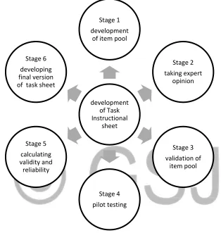
Figure 1: Developmental Research Procedure for Electrical Installation Task Instructional Sheet
The reliability of the task instructional sheet was determined using a pilot test of 20 students
from a school in the study population. A standard test of internal consistency of Cronbach Alpha
was used for determining the reliability coefficient. This yielded a value of 0.84, indicating a
high reliability index.
Method of Data Collection
Data for the study were collected using questionnaire, focus group discussion employing
a DACUM chart, Delphi technique and during the practical sessions. Supervisors from industries
development of Task Instructional
sheet Stage 1 development
of item pool
Stage 2 taking expert
opinion
Stage 3 validation of
item pool
Stage 4 pilot testing Stage 5
calculating validity and
were involved in the DACUM process, where they brainstormed on tasks that are essential for
electrical installation. This went on for a period of 21 working days. The input from industries
was then presented to experts in the Delphi technique, who screened the items to ensure that they
served as inputs to education. Seven experts were involved in the Delphi process. The researcher
utilized the services of trained research assistants in administering the questionnaire to
respondents across the study area.
Method of Data Analysis
The data generated was analysed using Mean, standard deviation to answer research the
question one, while content validity of the process (psychomotor) component of the task
instructional sheet was determined using Lawshe’s content validity index (CVI). The construct
and criterion validity of the task instructional sheet was also determined using factor analysis and
Pearson product moment correlation (PPMC) respectively. Following a detailed review of
NABTEB curriculum for the award of National Technical certificate (NTC) in electrical
installation and maintenance works, installation of concealed PVC was identified as a major
practical skill area for assessment in the NABTEB curriculum. Hence, performance objectives
relating to this skill area were isolated from the curriculum. Based on the critical review of
relevant literature, these objectives were transformed into basic task statements. Cronbach Alpha
was used for determining the internal consistency of the task instructional sheet. The
recommended alpha coefficient of 0.70 by Tavakol and Dennick (2011) was used to set the
criteria for the reliability coefficient test score acceptability limit.
Data Presentation
Research Question One: What are the contents of the task instructional sheet in electrical
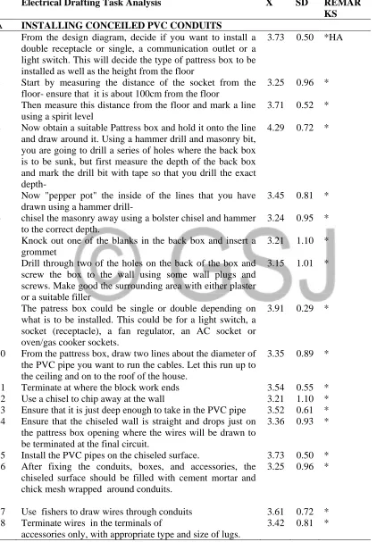
Table 1: Respondents’ Mean Ratings on the Process Skills Content of the Task Instructional Sheet in Electrical Installation and Drafting
Electrical Drafting Task Analysis X SD REMAR KS A INSTALLING CONCEILED PVC CONDUITS
1 From the design diagram, decide if you want to install a double receptacle or single, a communication outlet or a light switch. This will decide the type of pattress box to be installed as well as the height from the floor
3.73 0.50 *HA
2 Start by measuring the distance of the socket from the floor- ensure that it is about 100cm from the floor
3.25 0.96 * 3 Then measure this distance from the floor and mark a line
using a spirit level
3.71 0.52 * 4 Now obtain a suitable Pattress box and hold it onto the line
and draw around it. Using a hammer drill and masonry bit, you are going to drill a series of holes where the back box is to be sunk, but first measure the depth of the back box and mark the drill bit with tape so that you drill the exact depth-
4.29 0.72 *
5 Now "pepper pot" the inside of the lines that you have drawn using a hammer drill-
3.45 0.81 * 6 chisel the masonry away using a bolster chisel and hammer
to the correct depth.
3.24 0.95 * 7 Knock out one of the blanks in the back box and insert a
grommet
3.21 1.10 * 8 Drill through two of the holes on the back of the box and
screw the box to the wall using some wall plugs and screws. Make good the surrounding area with either plaster or a suitable filler
3.15 1.01 *
9 The patress box could be single or double depending on what is to be installed. This could be for a light switch, a socket (receptacle), a fan regulator, an AC socket or oven/gas cooker sockets.
3.91 0.29 *
10 From the pattress box, draw two lines about the diameter of the PVC pipe you want to run the cables. Let this run up to the ceiling and on to the roof of the house.
3.35 0.89 *
11 Terminate at where the block work ends 3.54 0.55 * 12 Use a chisel to chip away at the wall 3.21 1.10 * 13 Ensure that it is just deep enough to take in the PVC pipe 3.52 0.61 * 14 Ensure that the chiseled wall is straight and drops just on
the pattress box opening where the wires will be drawn to be terminated at the final circuit.
3.36 0.93 *
15 Install the PVC pipes on the chiseled surface. 3.73 0.50 * 16 After fixing the conduits, boxes, and accessories, the
chiseled surface should be filled with cement mortar and chick mesh wrapped around conduits.
3.25 0.96 *
17 Use fishers to draw wires through conduits 3.61 0.72 * 18 Terminate wires in the terminals of
accessories only, with appropriate type and size of lugs.
19 If wires become kinked while you work, they get stuck. Have a helper feed the wire carefully from one end of the conduit while you pull at the other end. If you work alone, precut the wires (leave yourself an extra 2 feet or so) and unroll them so they can slide smoothly through the conduit.
3.17 0.95 *
Team Up to Pull Wire Through Conduit.
Pull wires from box to box. If there are more than three turns between boxes, use a pulling elbow. For longer runs use a fish tape
3.15 1.11 *
20 Push the fish tape into conduit and fold wires over fish tape 3.06 0.98 * 21 To attach multiple wires to a fish tape, strip the outer
insulation from the wires and wrap the bare wires through the eye on the end of the fish tape. Twist a strand around all of the wires attached and wrap the whole head of the wire connection with electrical tape. Adding wire pulling lubricant makes the pull much easier.
3.83 0.38 *
22 Strip 6 inches of insulation from one wire, 8 inches from another wire, 10 inches from a third wire, and so on. Fold the wires over the fish tape, as shown, and wrap tightly with electrician's tape.
3.32 0.89 *
23 Pull smoothly, using long strokes to avoid stopping and starting. If the wires get stuck, back up a foot or so and start again.
3.47 0.57 *
24 This process is repeated for all the wirings to be placed in the conduit. The same process is done for lighting wiring, socket outlets, power outlets like HVAC systems. The differences in the cable size, position of pattress box and whether it should be a single or double pattress box
3.14 1.09 *
B LIGHTING CONNECTIONS Wiring a Ceiling Rose
25 Create an aperture in the ceiling about the diameter of the ceiling rose to be installed using chasers
3.46 0.61 *HA 26 Check to see if the ceiling rose fits the aperture 3.31 0.92 * 27 Ensure that a wooden slab is nearby where the screws of
the ceiling rose will be tightened to the ceiling
3.60 0.72 * 28 Using an indelible marker pen, mark the end of the three
live conductors
3.69 0.53 * 29 Connect all the live conductors to the same connector
section.
3.15 1.11 * 30 Do the same for the neutral conductors by connecting them
to the same connector section separate from the live connectors.
3.06 0.98 *
31 Connect all the earth wires to a new section of the connectors
3.50 0.55 * 32 After this has been done, connect a neutral wire to the
neural section of the connectors in the ceiling rose and draw to the lamp holder
3.12 1.09 *
33 Connect a fresh wire to the live section of the ceiling rose draw that wire to the switch and connect at one side of the light switch.
3.46 0.61 *
draw to the lamp holder
35 Connect the live wire from the switch to the live section of the lamp holder
3.60 0.72 * 36 Connect the neutral wire from the ceiling rose to the
neutral section of the lamp holder.
3.72 0.50 * 37 Install the light at the appropriate place based on the design 3.12 1.09 * 38 Use two wires to connect the lamp to the lamp holder by
looping the wires to the neutral and live ends of the lamp holder separately.
3.08 1.03 *
39 This process is repeated at every installed ceiling rose for each lighting point
3.79 0.41 * 40 Check for all loose ends and faults 3.67 0.52 * 41 The live feed from the Consumer unit (fuse board) feeds
into the first ceiling rose (ceiling rose A).
3.92 0.27 * 42 from this feed, power can then be looped into other ceiling
rose down to the last lighting point
3.81 0.40 * This process is repeated for all the other ceiling rose until
the last lighting point is connected
3.71 0.60 * C CONNECTING RECEPTACLES- general and
specialized (power circuits)
43 Prepare the circuit cable(s), as needed (2.5mm2 for general receptacles, 4mm2 for HVAC socket outlets)
3.81 0.40 *HA 44 Cut through the sheathing, or outer jacket, of each cable,
using a cable ripper. Clamp the ripper over the cable and pull the tool toward the end of the cable to cut through the sheathing
3.88 0.32 *
45 Peel the sheathing away from the wires inside the cable and trim it off about 1/2 to 1 inch from where the cable is clamped to the electrical box, using cutting pliers or a utility knife
3.61 0.75 *
46 Strip 3/4 inch of insulation from the end of each insulated wire in the box, using a wire stripper.
3.75 0.49 * 47 Install pigtails if there is more than one cable in the box.
Using a scrap of the same type of circuit cable, cut 6-inch lengths of each type of wire in the cable and strip 3/4 inch of insulation from each end of the wire. Join the bare copper (or green insulated) ground wire to the ground wires in the circuit cables using a wire connector, following the manufacturer's directions. Do the same with the white (neutral) wires, then the black (hot) wires, so you have one ground, one white and one black pigtail.
Note: If the electrical box is metal, install an additional grounding pigtail and connect it to the ground screw on the box.
3.66 0.65 *
48 Form a U-shaped hook on the end of each wire (or pigtail), using needle nose pliers. Fit the hooked end of the ground wire around the ground screw of the new outlet so the open end of the wire is on the right. Use the pliers to squeeze the hook closed around the threaded shank of the screw. Tighten the ground screw with a Phillips screwdriver.
3.51 0.61 *
yellow (neutral) screw terminals on the outlet, using the same techniques used for the ground screw. Connect the black hot wire or pigtail to one of the brown (hot) screw terminals on the outlet.
50 Confirm that all wiring connections are secure by gently tugging on each wire. Reconnect and retighten any loose wires.
3.64 0.71 *
51 Carefully tuck the wires into the box; it often helps to bend them in one or two places, but do not create sharp bends.
3.76 0.49 * 52 Hold the outlet against the box edge and secure it to the
box with the screw at the top and bottom of the outlet.
3.19 1.10 * 53 Fit the outlet cover plate over the outlet and secure it to the
box with one or two screws, as applicable. Restore power to the circuit by switching on the circuit breaker. Plug in an electrical device to the outlet to make sure the outlet is working properly
3.92 0.28 *
54 All general receptacles in a room can be connected using the ring method. Junction boxes are used to terminate the ring circuit, from where it is looped to the mains. These connections for a conduit system are usually done in the ceiling or suspended roof beyond sight.
3.60 0.75 *
D Earthing System Installation
55 Step 1. With post hole diggers or a powered post hole drill, dig a hole as deep as you can or as long as the ground rod. The rod need only stick out of the ground enough to make a wire connection. If the rod is longer than the hole is deep, pound the rod in to accommodate the size differences.
3.63 0.55 *HA
56 Drive the electrode into the ground with a post driver.The pipe is placed at 3.75 meters.
3.41 0.97 * 57 Step 2. Back fill the hole with
a) bentonite if the rod is installed in an environment which will not freeze,
b) or an 80/20 mixture of concrete and charcoal of which the charcoal is pulverized to a powder.
3.61 0.52 *
58 Concrete can now be poured over the mixture. But ensure that the copper rod protrudes from the ground
3.42 0.93 * 59 Make wire connections using 6 to no less than 10 gage
solid copper wire. Make the wire run as straight as possible. If the installer will need to make turns, use wide sweeping bends. Do not put sharp bends in the wire. Use a good quality copper clamp to attach the wire to the rod using at the minimum a sturdy ground clamp. The preferred method would be to weld the wire to the rod utilizing a flash type welding kit. Do not just wrap the wire around the rod.
3.78 0.43 *
60 Insert the other end of the copper wire to the main panel's ground (neutral) service conductor and tighten the screw.
3.74 0.51 * E INSTALLING THE DISTRIBUTION BOARD
61 Measure the diameter of the DB 3.43 0.93 *HA 62 Replicate the measurement of the DB on the wall where the
DB is to be installed
63 Cut away the space for installing DB 3.93 0.25 * 64 Ensure that the depth of the space will fit the DB normally 3.82 0.43 * 65 Inspect and install the feeder pipe first. 3.29 0.98 * 66 Install the connector into the panel 3.79 0.52 * 67 when using a metal pipe, place a plastic bushing over the
connector threads.
4.03 0.68 * 68 Level the panel and insert screws through the holes
provided in the back of the panel
3.32 0.85 * 69 Using a tape, pull the electrical feeder wires through the
feeder pipe.
3.24 0.96 * 70 Leave enough wire to get to the opposite side of the panel. 3.16 1.15 * 71 Bend the two black wires to shape them for easy
installation to the main breaker.
3.07 1.07 * 72 Excess bare wire leaves a safety hazard where the wires
can come in contact with other wires and cause a short circuit.
3.82 0.40 *
73 Connect the neutral wire to the neutral buss. The neutral buss is located on either side of the breakers. It is a silver-colored bar with many smaller screws and connection points
3.19 0.93 *
74 Connect all of the green and bare copper wires to the ground buss bar.
3.45 0.56 * 75 If the wires were bent ahead of time, ensure to have a nice,
neat wire installation that looks uniform.
3.16 1.15 * 76 Next, install the circuit feeds to the branch circuit
breakers.
3.45 0.69 * 77 Connect the appropriate sized wire to the correctly rated
breaker.
3.29 0.92 * 78 Bend the wires so that they keep a neat appearance when
the installation is complete.
3.69 0.71 * F WIRING THE DB
79 Kitchen sockets are wired with a 4mm cable and connected to a 32A MCB in the DB.
3.48 0.82 *HA 80 HVACs such as cookers, oven, air conditioning units are
wired with a minimum 4mm cables and each is connected separately to a MCB of 32A in the DB
3.16 1.03 *
81 Socket outlets are connected with a 20A-32A MCB 3.14 1.15 * 82 Light circuits are connected with a 15A MCB in the DB 3.52 0.78 * 83 Ensure that the DB connection allows for additional
appliances to be added in the installation by allowing for free spaces in the DB
3.29 0.98 *
84 Sockets in a room can all be connected to the same MCB. That is if there are 3 sockets in a room, they can all be connected to the same MCB. This is done by connecting all the neutral wires to the neutral section of the DB and connecting the live wires to the same MCB. That is three red wires are connected to one MCB.
3.20 1.11 *HA
85 This technique is repeated for lighting points 3.48 0.82 *HA
Table 1 shows the summary of the Mean and standard deviation scores of respondents on
the electrical drafting and installation tasks to be included in the PBL-Instructional package. The
analysis shows that the Mean ( ̅) and standard deviation (σ) scores ranges from 3.06 – 4.35 and
0.25 – 1.12 respectively. The result shows that all the items have Mean ( ̅) responses above 3.0
the cut-off mean. This indicates that all the respondents agreed that the tasks were highly
appropriate to be included in the task instructional sheet.
Research Question 2:How valid are the developed PBL training modules for effective PBL environment in technical education?
Determining Content Validity
The content validity of instrument was qualitatively and quantitatively analysed using panel of
seven (7) experts comprising three lecturers in Technical Education, specifically, with majors in
electrical technology, two lecturers in Curriculum planning and management and two electrical
installation and design supervisors in industries. In ascertaining the qualitative content validity of
the Task instructional sheet, content experts and target group’s recommendations are adopted on
observing grammar, using appropriate and correct words, applying correct and proper order of
words in items, review of tasks identified as well as appropriate scoring. owever, in
determining the quantitative content validity of the process component of the task sheet,
Lawshe’s content validity ratio (CVR) method was employed. From the result of analysis, the
Scale-Content Validity Index (S-CVI) ranged from 0.71- 1.0. 18 items have scale content
validity index (S-CVI) of 0.71 while the rest have CVI of 1.0. A CVI of 0.71-0.79 indicates that
the item should be revised, while a CVI of 0.80-1.0, indicates that the task is appropriate and
should be included.
Two main types of criterion validity are tested. These are the concurrent and predictive
validity.
Concurrent validity is determined by comparing tests scores of students to a measure of their job
performance, both measured at approximately the same time.
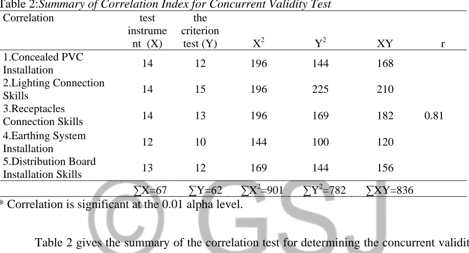
Table 2:Summary of Correlation Index for Concurrent Validity Test
Correlation test
instrume nt (X)
the criterion
test (Y) X2 Y2 XY r
1.Concealed PVC
Installation 14 12 196 144 168
0.81 2.Lighting Connection
Skills 14 15 196 225 210
3.Receptacles
Connection Skills 14 13 196 169 182
4.Earthing System
Installation 12 10 144 100 120
5.Distribution Board
Installation Skills 13 12 169 144 156
∑X=67 ∑Y=62 ∑X2=901 ∑Y2=782 ∑XY=836
* Correlation is significant at the 0.01 alpha level.
Table 2 gives the summary of the correlation test for determining the concurrent validity
of the instrument. The degree to which the test and criterion are correlated is the degree to which
the test is a valid indicator of the trait measured by the criterion. The correlation index is 0.81,
indicating a high correlation coefficient between the test instrument and the criterion test. Thus,
the instrument has a high validity coefficient and hence, a high criterion validity.
Determining the Predictive Validity
Predictive criterion-related validity is the correlation between test scores and future job
performance. Such a test is done within a time interval of each other. The students were tested
based on the task instructional sheet. Afterwards, a job performance test was also administered to
Table 3:Summary of Correlation Index for Predictive Validity Test Correlation
test instrume
nt (X)
Job Perform
ance
test (Y) X2 Y2 XY r
1.Concealed PVC
Installation 14 14 196 196 196
0.89 2.Lighting Connection
Skills 14 15 196 225 210
3.Receptacles Connection
skills 14 13 196 169 182
4.Earthing System
Installation 12 10 144 100 120
5.Distribution Board
Installation Skills 13 13 169 169 169
∑X=67 ∑Y=65 ∑X2=901 ∑Y2=859 ∑XY=877
* Correlation is significant at the 0.03 level.
Table 3 gives the summary of the correlation test for determining the predictive validity
of the instrument. This was done by correlating the test scores of students as against the job
performance test which was administered after a period. The index gives the extent of the
predictive validity. The validity coefficient gives a value of 0.89, which indicates a high
predictive validity index.
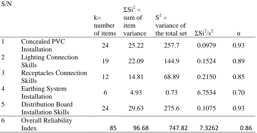
Research Question 3:What is the Reliability of the developed task instructional sheet? Table 4:Reliability of the Task Instructional Sheet in Electrical Installation
S/N
k= number of items
ΣSi2 = sum of item variance
S2 = variance of
the total set ΣSi2/s2 α 1 Concealed PVC
Installation 24 25.22 257.7 0.0979 0.93 2 Lighting Connection
Skills 19 22.09 144.9 0.1524 0.89
3 Receptacles Connection
Skills 12 14.81 68.89 0.2150 0.85
4 Earthing System
Installation 6 4.93 0.73 6.7534 0.70
5 Distribution Board
Installation Skills 24 29.63 275.6 0.1075 0.93 6 Overall Reliability
Cronbach Alpha reliability test was used to determine the internal consistency of
the Electrical Installation task instructional sheet. Reliability analysis for each factor was
performed applying Cronbach alpha technique. The overall reliability coefficient is 0.86. The
alpha coefficients are above the recommended value of 0.70 (Tavakol & Dennick, 2011).
Therefore, the developed PBLIPEDI and its clusters are highly reliable.
Discussion of Findings
Validity of the Problem-Based Learning Training Modules
The validity of the study is discussed under the following subheadings
(a). Content Validity of the task instructional sheet in Electrical Installation
The quantitative index content validity evaluation gives strong support to the job
relatedness of the task instructional sheet. The data analysis yielded high correlations, indicating
a significant degree of overlap between training curriculum content and job task domain. The
Scale-Content Validity Index (S-CVI) ratio ranges from 0.71- 1.0. 18 items have scale content
validity index (S-CVI) of 0.71 while the rest have CVI of 1.0. A CVI of 0.71-0.79 indicates that
the item should be revised, while a CVI of 0.80-1.0, indicates that the task is appropriate and
should be included. This finding is in line with Sangoseni et al. which proposed a S-CVI of
≥0.78 as significant level for inclusion of an item into the study. Furthermore, the findings agree
with Polit and Beck (2006) who recommended the CVR as an appropriate indicator of content
validity based on a comparative evaluation of the CVR and alternative indexes.
(b). Concurrent Validity of the Problem-Based Learning Instructional Package in Electrical Drafting and Installation (PBLIPEDI)
Concurrent criterion-related validity measures the correlation between employee
time. The correlation coefficient gives the validity coefficient. The PBLIPEDI was administered
to the students, thereafter, the students were given a real work test. The test scores were
correlated and yielded a coefficient of 0.81. Based on the high coefficient score, the validity
coefficient is very high and the instrument is said to have a high concurrent criterion validity.
This is in line with Jeffrey (2001) which averred that to measure the criterion validity of a test,
researchers must calibrate it against a known standard or against itself. In his research, he found
that the relationship between test performance and a job/occupational metric can be quantified by
a correlation coefficient (ranging from -1.0 to +1.0), which can be used to demonstrate how
strongly correlated two variables are depending on how close the number is to -1.0 or +1.0.
(c). Predictive Validity of the Problem-Based Learning Instructional Package in Electrical Drafting and Installation (PBLIPEDI)
The predictive criterion related validity was determined to see how likely it is that test
scores in the PBLIPEDI could predict future job performance. The validity coefficient gave an
index of 0.89. Based on the high validity coefficient, the instrument was said to have high
predictive criterion validity. These findings are in line with Jeffrey (2001) which found that if an
employer's selection testing program is truly job-related, it follows that the results of its selection
tests should accurately predict job performance. In other words, there should be a positive
correlation between test scores and future job performance. Predictors may include ability tests,
work samples, interview ratings, personality inventories, or ratings of experience. For example,
an electrical test can be considered to have high criterion-related validity if it correlates
positively with the job performance of an electrical technologist.
Conclusion
Based on the findings of the study, it is concluded that the developed task instructional
teachers for implementing Problem-Based Learning environments in technical education
programmes. The training modules if followed by the technical teachers, would help in
developing key competencies in concealed PVC wiring and installation.
Recommendations
Based on the findings of this study, the following recommendations were
made:
1. Technical teachers should adopt the developed task instructional sheet and apply them in
technical training institutions.
2. Further curriculum development initiatives by the NBTE should consider the Developing
A CUrriculuM (DACUM) process, where current trends and experts in the occupation have a say on what is to be taught to students.
3. Technical teachers should explore the use of hybrid models of instruction utilizing PBL
and demonstration methods blended together.
References
Davis, L.L.(1992). Instrument review: Getting the most from a panel of experts. Applied Nursing Research, 5,194-197.
DeSimone, R.L., Werner, J.M. & Harris, D.M. (2002). Human Resource Development. Orlando, FL.: Harcourt, Inc.
Elizabeth, G., Jocelyn D., & Simon, F. (2006). Principles of learning: Advancing performance in today’s workplace. The Forum Corporation of North America. Paper No FOR5102.
Gay, L. R. (1996). Educational research. competences, for analysis and application. (5th Edition), Prentice Hall, Merrill, NJ, USA.
Jeffrey, H.(2001).Job analysis and selection. Validity and Reliability 23-35.
Norton, R. E., & Moser, J. (2008). DACUM handbook (3rd Ed.). Columbus, OH: Center on Education and Training for Employment, the Ohio State University.
Polson, C.M.(1993). Task analysis for an automated instructional design advisor. In J. Michael, M. Polson & D. Muraida (Eds). Automating instructional design: Concepts and issues. (pp. 219-248). Englewood cliffs, NJ: Educational Technology publishers.
Sangoseni, O., Hellman, M. & Hill C. (2013).Development and validation of a questionnaire to assess the effect of online learning on behaviours, attitude and clinical practices of physical therapists in United States regarding of evidence based practice. International Journal of Allied Health Science Practitioners, 11, 1-12.