Volume 2007, Article ID 60539,27pages doi:10.1155/2007/60539
Review Article
An Overview on Wavelets in Source Coding,
Communications, and Networks
James E. Fowler1and B ´eatrice Pesquet-Popescu2
1Department of Electrical & Computer Engineering, GeoResources Institute, Mississippi State University, P.O. Box 9627, Mississippi State, MS 39762, USA
2D´epartement Traitement du Signal et des Images, ´Ecole Nationale Sup´erieure des T´el´ecommunications, 46 rue Barrault, 75634 Paris, France
Received 7 January 2007; Accepted 11 April 2007
Recommended by Jean-Luc Dugelay
The use of wavelets in the broad areas of source coding, communications, and networks is surveyed. Specifically, the impact of wavelets and wavelet theory in image coding, video coding, image interpolation, image-adaptive lifting transforms, multiple-description coding, and joint source-channel coding is overviewed. Recent contributions in these areas arising in subsequent papers of the present special issue are described.
Copyright © 2007 J. E. Fowler and B. Pesquet-Popescu. This is an open access article distributed under the Creative Commons Attribution License, which permits unrestricted use, distribution, and reproduction in any medium, provided the original work is properly cited.
1. INTRODUCTION
Wavelet transforms are arguably the most powerful, and most widely-used, tool to arise in the field of signal pro-cessing in the last several decades. Their inherent capac-ity for multiresolution representation akin to the operation of the human visual system motivated a quick adoption and widespread use of wavelets in image-processing applica-tions. Indeed, wavelet-based algorithms have dominated im-age compression for over a decade, and wavelet-based source coding is now emerging in other domains. For example, re-cent wavelet-based video coders exploit wavelet-based tem-poral filtering in conjunction with motion compensation to yield effective video compression with full temporal, spatial, and fidelity scalability. Additionally, wavelets are increasingly used in the source coding of remote-sensing, satellite, and other geospatial imagery. Furthermore, wavelets are start-ing to be deployed beyond the source-codstart-ing realm with increased interest in robust communication of images and video over both wired and wireless networks. In particu-lar, wavelets have been recently proposed for joint source-channel coding and multiple-description coding. This spe-cial issue collects a number of papers that explore these and other latest advances in the theory and application of wavelets.
Here, in this introductory paper to the special issue, we provide a general overview of the application of wavelets and
wavelet theory to the signal representation, source coding, communication, and network transmission of images and video. The main body of this paper is partitioned into two major parts: we first cover wavelets in signal representation and source coding, and then explore wavelets in communi-cations and networking. Specifically, inSection 2, we focus on wavelets in image coding, video coding, and image inter-polation, as well as image-adaptive lifting transforms. Then, in Section 3, we explore the use of wavelets in multiple-description coding and joint source-channel coding as em-ployed in communication and networking applications. Fi-nally, we make some concluding remarks inSection 4. Brief overviews of the papers in the special issue are presented at the end of relevant sections throughout this introductory paper—these overviews are demarked by boldfaced headings to facilitate their location.
2. WAVELETS IN SIGNAL REPRESENTATION AND SOURCE CODING
applied. Combining such a signal representation with quan-tization and some form of bitstream generation yields im-age/video compression schemes; suchsource coding consti-tutes perhaps the most widespread practical application of wavelets. In this section, we overview the role of wavelets in current applications of both signal representation and source coding. First, we focus on source coding by examin-ing the use of wavelets in image and video coders in Sections 2.1 and2.2, respectively. InSection 2.3, we discuss image-adaptive wavelet transforms that have been proposed to im-prove signal-representation capabilities by adapting to local image features. Finally, inSection 2.4, we explore wavelet-based signal representations for the interpolation (magnifi-cation) of image data.
2.1. Image coding
Over the last decade, wavelets have established a dominant presence in the task of 2D image compression, and they are increasingly being considered for the compression of 3D im-agery as well. Wavelets are attractive in the image-coding problem due to a tradition of excellent rate-distortion per-formance coupled with an inherent capacity forprogressive transmissionwherein successive reconstructions of the image are possible as more and more of the compressed bitstream is received and decoded. Below, we overview several salient concepts in the field of image coding, including multidi-mensional wavelet transforms, coding procedures applied to such transforms, as well as coding methodology for general imagery of shape other than traditional rectangular scenes (i.e., shape-adaptive coding). The reader is referred elsewhere for more comprehensive and in-depth surveys of 2D image coding (e.g., [1]), 3D image coding (e.g., [2]), and shape-adaptive coding (e.g., [3]).
2.1.1. Multidimensional wavelet transforms
A single stage of a 1D discrete wavelet transform (DWT) de-composes a 1D signal into a lowpass signal and a highpass signal. Multidimensional wavelet decompositions are typi-cally constructed by such 1D wavelet decompositions applied independently along each dimension of the image dataset, producing a number of subbands. The decomposition proce-dure can be repeated recursively on one or more of the sub-bands to yield multiple levels of decomposition of lower and lower resolution.
The most commonly used multidimensional DWT struc-ture consists of a recursive decomposition of the lowest-resolution subband. Thisdyadicdecomposition structure is illustrated for a 2D image in Figure 1(a). In a 2D dyadic DWT, the original image is decomposed into four subbands each being one fourth the size of the original image, and the lowest-resolution subband (thebaseband) is recursively decomposed. The dyadic transform structure is trivially ex-tended to 3D imagery as illustrated inFigure 1(b)—a single stage of 3D decomposition yields 8 subbands with the base-band recursively decomposed for a 3D dyadic transform.
Alternative transform structures arise when subbands other than, or in addition to, the baseband are subjected to further decomposition. Generally referred to as wavelet-packet transforms, these decomposition structures can be fixed (like the dyadic structure), or be optimally adapted for each image coded (i.e., a so-called best-basistransform structure [4]). Packet transforms offer the potential to better match the spatial or spatiotemporal characteristics of certain imagery and can thereby at times yield greater coding effi -ciency. Although not widely used for 2D image coding,1fixed packet transforms, such as those illustrated inFigure 2, have been extensively deployed in 3D image coders and often yield coding efficiency substantially superior to that of the dyadic transform ofFigure 1(b). In particular, the packet structure ofFigure 2(a)has been shown to be near optimal in certain applications, producing coding performance nearly identical to the optimal packet decomposition structure chosen in a rate-distortion best-basis sense [6,7].
Although there are many possible wavelet-transform fil-ters, image-coding applications almost exclusively rely on the ubiquitous biorthogonal 9/7 transform of [14] or the simpler biorthogonal 5/3 transform of [15]. Biorthogonality facili-tates symmetric extension at image boundaries and permits linear-phase FIR filters. Furthermore, experience has shown that the biorthogonal 9/7 offers generally good coding per-formance [16], while the biorthogonal 5/3 is attractive for reducing computational complexity or for implementation of reversible, integer-to-integer transformation [17,18]. In fact, the biorthogonal 9/7 and an integer-valued biorthogo-nal 5/3 are the only transforms permitted by Part 1 of the JPEG2000 standard [13], although coding extensions of Part 2 [19] of the standard permit a greater variety of trans-forms.
2.1.2. Coding procedures
Many wavelet-based coders for 2D and 3D images are based on the following observations which tend to hold true for dyadic decompositions of many classes of imagery: (1) since most images are lowpass in nature, most signal energy is compacted into the lower-resolution subbands; (2) most co-efficients are zero for high-resolution subbands; (3) small- or zero-valued coefficients (i.e.,insignificant coefficients) tend to be clustered together within a given subband; and (4) clusters of insignificant coefficients in a subband tend to be located in the same relative position as similar clusters in the subband of the same orientation at the next higher-resolution level.
Wavelet-based image coders typically implement the fol-lowing coding procedure. DWT coefficients are represented in sign-magnitude form with the signs and magnitudes coded separately. Coefficient magnitudes are successively ap-proximated via bitplane coding wherein the most signifi-cant bit of all coefficient magnitudes is coded, followed by the next-most significant bit, and so forth. In practice,
1The WSQ fingerprint coding standard [5] is one example of a fixed packet
B3 V3
H3 D3 V2
H2 D2
V1
H1 D1
(a) (b)
Figure1: Dyadic DWT with three levels of decomposition. (a) 2D; (b) 3D.
(a) (b)
Figure2: Examples of 3D wavelet-packet DWTs with three levels of decomposition. (a) 2D dyadic plus independent 1D dyadic; (b) three independent 1D dyadic transforms.
such bitplane coding is usually implemented by perform-ing two codperform-ing passes through the set of coefficients for each bitplane—a significance passand arefinement pass. In essence, the significance pass describes the first bitplane holding a nonzero bit for all the coefficients in the DWT while the refinement pass produces a successive approxima-tion of each coefficient after its most significant nonzero bit is coded. The significance pass works by successively coding a map—thesignificance map—of coefficients which are in-significant relative to a threshold; the primary difference be-tween wavelet-based coders lies in how this significance-map coding is performed.Table 1presents an overview of promi-nent significance-map coding strategies which we discuss in detail below.
Zerotreesare one of the most widely used techniques for coding significance maps in wavelet-based coders. Zerotrees capitalize on the fact that, in dyadic transforms, insignifi-cant coefficients tend to cluster together within a subband,
Table1: Strategies for significance-map coding in wavelet-based still image coders.
Strategy Prominent examples Methodology Notes
Zerotrees EZW [8], SPIHT [9] Cross-scale trees of coeplus arithmetic codingfficients Widely used
Set partitioning SPECK [10,11], BISK [12] Set splitting into subsets plusarithmetic coding No cross-subband processing
Conditional coding JPEG2000 [13]
Multicontext arithmetic coding of small blocks; arithmetic coding; optimal block truncation
Superior rate-distortion performance; cross-subband processing confined to block-truncation process
(a) (b)
Figure3: Zerotrees in (a) the 2D dyadic transform ofFigure 1(a), (b) the 3D packet transform ofFigure 2(a).
asymmetric zerotreestructure originating in [25] and illus-trated inFigure 3(b)typically provides the best performance for the packet transform ofFigure 2(a).
Despite the prominence of zerotree-based algorithms, re-cent work [28] has indicated that, typically, the ability to predict the insignificance of a coefficient through cross-scale parent-child relationships is somewhat limited compared to the predictive ability of neighboring coefficients within the same subband. Consequently, recent algorithms have fo-cused on coding significance-map information using only within-subband information. An alternative to zerotrees for significance-map coding is within-bandset partitioning. The set-partitioning embedded block coder (SPECK) [10, 11], originally developed as a 2D image coder, employs quadtree partitioning (seeFigure 4(a)) to locate significant coefficients within a subband; a 3D extension (3D-SPECK [29,30]) re-places quadtrees with octrees as illustrated in Figure 4(b). A similar approach is embodied by the binary set splitting with k-d trees (BISK) algorithm in both its 2D (2D-BISK [12]) and 3D (3D-BISK [3, 31]) variants wherein sets are always partitioned into two subsets. An advantage of these set-partitioning algorithms is that sets are confined to reside within a single subband at all times throughout the algo-rithm, whereas zerotrees span across multiple transform
res-olutions. Not only does this fact entail a simpler implementa-tion, it is also beneficial from a computational standpoint as the coder must buffer only a single subband at a given time, leading to reduced dynamic memory needed [11]. Further-more, the SPECK and BISK algorithms are easily applied to both the dyadic and packet transform structures of Figures 1(b),2(a), and2(b)with no algorithmic differences.
(a)
(b)
Figure4: Set partitioning. (a) 2D quadtree partitioning. (b) 3D oc-tree partitioning.
In JPEG2000, the method for codeblock-bitstream trun-cation is typically a Lagrangian rate-distortion optimal tech-nique,post-compression rate-distortion (PCRD) optimization [32,35]. PCRD optimization is performed simultaneously across all of the codeblocks from the image, producing an optimal truncation point for each codeblock. The truncated codeblocks are then concatenated together to form a single bitstream. The PCRD optimization, in effect, distributes the total rate for the image spatially across the codeblocks in a rate-distortion-optimal fashion such that codeblocks with higher energy, which tend to more heavily influence the dis-tortion measure, tend to receive greater rate. Additionally, the truncated codeblock bitstreams are interleaved in an opti-mal order such that the final bitstream is close to being rate-distortion optimal at many truncation points. As described in Part 1 of the standard, JPEG2000 is, in essence, a 2D im-age coder. However, for 3D imim-agery, the coding extensions available in Part 2 of the standard can effectuate the packet transform of Figure 2(a), and the PCRD optimization can be applied across all three dimensions; this strategy for 3D images has been called “JPEG2000 multicomponent” [36]. We note that JPEG2000 with truly 3D coding, consisting of arithmetic coding of 3D codeblocks as in [37], is under de-velopment as JPEG2000 Part 10 (JP3D), an extension to the core JPEG2000 standard; however, the use of JPEG2000 mul-ticomponent currently remains widespread for 3D imagery. The reader is refered to [33,34] for useful introductions to the JPEG2000 standard.
Figures 5 and 6 illustrate typical coding performance for some of the prominent 2D and 3D wavelet-based image coders discussed above. For 2D images, distortion is usually measured as a peak signal-to-noise ratio (PSNR), defined as
PSNR=10 log10255 2
D , (1)
whereDis the mean square error (MSE) between the origi-nal image and the reconstructed image; for 3D images, typ-ically an SNR is used where 2552 in (1) is replaced by the
26 28 30 32 34 36
PSNR
(dB)
0.1 0.2 0.3 0.4 0.5 0.6 0.7 0.8 0.9 1 Rate (bpp)
JPEG-2000 SPIHT
SPECK JPEG
Figure5: Rate-distortion performance for the 2D “barbara” im-age comparing the wavelet-based JPEG2000, SPIHT, and SPECK coders, as well as the original JPEG standard [38, 39]. The Qc-cPack [40] (http://qccpack.sourceforge.net) implementations for SPIHT and SPECK are used, while JPEG-2000 is Kakadu Ver. 5.1 (http://www.kakadusoftware.com) and JPEG is the Independent JPEG Group implementation (http://www.ijg.org). The wavelet-based coders use a 5-stage wavelet decomposition with 9–7 wavelet filters.
28 30 32 34 36 38 40 42 44 46
SNR
(dB)
0.1 0.2 0.3 0.4 0.5 0.6 0.7 0.8 0.9 1 Rate (bpppb)
JPEG-2000 3D-SPIHT 3D-SPECK
(a) (b)
Figure7: (a) Original scene. (b) Arbitrarily shaped image objects to be coded with shape-adaptive coding.
dataset variance. Both the PSNR and SNR have units of deci-bels (dB). The bitrate is measured in terms of bits per pixel (bpp) for 2D images and typically bits per voxel (bpv) for 3D imagery (equivalently bits per pixel per band (bpppb) for hyperspectral imagery consisting of multiple spectral bands). We see in Figures5and6that JPEG2000 offers performance somewhat superior to that of the other techniques for both 2D and 3D coding.
In this special issue, the work “Adaptation of zerotrees using signed binary digit representations for 3D image cod-ing” by E. Christophe et al. presents a 3D zerotree-based coder operating on hyperspectral imagery decomposed with the packet transform ofFigure 2(a). The 3D-EZW algorithm is modified so as to eliminate the refinement pass (called the “subordinate” pass in the context of EZW [8]). Elimi-nating the subordinate pass, which typically entails a sorted list, simplifies the algorithm implementation but decreases coding efficiency. However, the use of a signed-binary-digit representation rather than the traditional sign-magnitude form for the wavelet coefficients increases the proportion of zero bits in the bitplanes, thereby increasing coding efficiency back to equal the original 3D-EZW implementation. Alsoin this special issue, “JPEG2000 compatible lossless coding of floating-point data” by B. E. Usevitch proposes extensions to the JPEG2000 standard to provide lossless coding of floating-point data such as that arising in many scientific applications. Several modifications to the JPEG2000 bitplane-coding pro-cedure and context conditioning are made to accommodate extended-integer representation of floating-point numbers.
2.1.3. Coding of arbitrarily shaped imagery
In traditional image processing—as is the case in the pre-ceding discussion—it is implicitly assumed that imagery has the shape of a rectangle (in 2D) or rectangular vol-ume (in 3D). The majority of image-coding literature ad-dresses the coding of only rectangularly shaped imagery. However, imagery with arbitrary, nonrectangular shape has become important in a number of areas, including multi-media communications (e.g., the arbitrarily shaped video
objects as covered by the MPEG-4 video-coding standard [41] and other approaches [42–47]), geospatial imagery (e.g., oceanographic temperature datasets [3,31,48,49], multi-spectral/hyperspectral imagery [50,51]), and biomedical ap-plications (e.g., mammography [52], DNA microarray im-agery [53–55]).Shape-adaptive image codingfor these appli-cations is usually achieved by adapting existing image coders designed for rectangular imagery to the shape-adaptive cod-ing problem.
In a general sense, shape-adaptive coding can be consid-ered to be the problem of coding an arbitrarily shaped im-agery “object” residing in a typically rectangularly shaped “scene” as illustrated inFigure 7. The goal is to code the im-age object without expending any bits towards the nonob-ject portions of the scene. Typically, an obnonob-ject “mask” will be required to be transmitted to the decoder separately in order to delineate the object from nonobject regions of the scene. Below we focus on object coding alone, assuming that any one of a number of lossless bilevel-image coding algo-rithms is used to provide an efficient representation of this binary object mask as side information to the central shape-adaptive image-coding task. Likewise, the segmentation of image objects from the nonobject background is considered an application-specific issue outside the scope of the shape-adaptive coding problem.
(such as explicitly discarding sets consisting of only nonob-ject regions from further consideration [3,12,31,43,44]) to increase performance. See [3] for a comprehensive overview of wavelet-based shape-adaptive coders.
In this special issue, the work “Costs and advantages of object-based image coding with shape-adaptive wavelet transform” by M. Cagnazzo et al. examines sources of in-efficiencies as well as sources of performance gains that re-sult from the application of shape-adaptive coding. It is ob-served that inefficiencies arise from both the reduced energy-compaction capabilities of the SA-DWT (due to less data for the DWT to process) as well as an interaction of the significance-map coding with object boundaries (e.g., in shape-adaptive SPIHT [43], zerotrees which overlap the ject/nonobject boundary). On the other hand, image ob-jects tend to be more coherent and “smoother” than full-frame imagery since object/nonobject boundary edges are not present in the object, a characteristic that may lead to coding gains. Experimental results in “Costs and advantages of object-based image coding with shape-adaptive wavelet transform” by M. Cagnazzo et al. provide insight as to the rel-ative magnitude of these losses and gains as can be expected in various operational conditions.
2.2. Video coding
The outstanding rate-distortion performance of the coders described above has led to wavelets dominating the field of still-image compression over the last decade. However, such is not the case for wavelets in video coding. On the contrary, the traditional architecture (illustrated inFigure 8) consisting of a feedback loop of block-basedmotion estima-tion(ME) andmotion compensation(MC) followed by a dis-crete cosine transform(DCT) of the residual is still widely em-ployed in modern video-compression systems and an inte-gral part of standards such as MPEG-2 [59], MPEG-4 [41], and H.264/AVC [60]. However, there has naturally been great interest in carrying over the gains seen by wavelet-based still-image coders into the video realm, and several diff er-ent approaches have been proposed. The first, and most straightforward, is essentially an adaptation of the traditional ME/MC feedback architecture to the use of a DWT, employ-ing a redundant transform to provide the shift invariance necessary to the wavelet-domain ME/MC process. A second approach involves eliminating the feedback loop of the tra-ditional architecture by applying ME/MC in an “open-loop” manner to drive a temporal wavelet filter. Finally, a recent strategy proposes eliminating explicit ME/MC altogether and instead relying on the greater directional sensitivities of a 3D complex wavelet transform to represent the motion of sig-nal features.Table 2overviews each of the these recent ap-proaches to wavelet-based video coding, and we discuss each one in detail below.
2.2.1. Redundant transforms and video coding
Perhaps the most straightforward approach to wavelet-based video coding is to simply replace the DCT with a DWT in
the traditional architecture ofFigure 8, thereby performing ME/MC in the spatial domain and calculating a DWT on the resulting residual image (e.g., [61]). This simple approach suffers from blocking artifacts [62], which are exacerbated if the DWT is not block based but rather the usual whole-image transform. An alternative paradigm would be to have ME/MC take place in the wavelet domain (e.g., [63]). How-ever, the fact that the critically sampled DWT used ubiqui-tously in image-compression efforts is shift variant has long hindered the ME/MC process in the wavelet domain [64,65]. It was recognized in [56,66, 67] that difficulties asso-ciated with the shift variance of traditional DWTs could be overcome by choosing instead to perform ME/MC in the do-main of a redundant transform. In essence, the redundant DWT (RDWT)2 [69–71] removes the downsampling oper-ation from the traditional DWT to ensure shift invariance at the cost of a redundant, or overcomplete, representation.
There are several equivalent ways to implement the RDWT, and several ways to represent the resulting over-complete set of coefficients. The most popular coeffi cient-representation scheme employed in RDWT-based video coders is that of a coefficient tree. This tree representation is created by employing filtering and downsampling as in the usual critically sampled DWT; however, all sets, or phases, of downsampled coefficients are retained and arranged in a tree-like fashion. The RDWT was originally formulated, however, as thealgorithme `a trousimplementation [69,70]. In this implementation, decimation following wavelet filter-ing is eliminated, and, for each successive scale of decompo-sition, the filter sequences themselves are upsampled, creat-ing “holes” of zeros between nonzero filter taps. As a result, the size of each subband resulting from an RDWT decom-position is exactly the same as that of the input signal, as is illustrated for a 2D image inFigure 9. By appropriately sub-sampling each subband of an RDWT, one can produce ex-actly the same coefficients as does a critically sampled DWT applied to the same input signal.
The majority of a prior work concerning RDWT-based video coding originates in the work of Park and Kim [56], in which the system shown in Figure 10 was proposed. In essence, the system ofFigure 10works as follows. An input frame is decomposed with a critically sampled DWT and partitioned into cross-subband blocks, wherein each block is composed of the coefficients from each subband that corre-spond to the same spatial block in the original image. A full-search block-matching algorithm is used to compute motion vectors for each wavelet-domain block; the system uses as the reference for this search an RDWT decomposition of the pre-vious reconstructed frame, thereby capitalizing on the shift invariance of the redundant transform. Any of the 2D image coders described above inSection 2.1.2is then used to code the MC residual. Subsequent work has offered refinements to the system depicted in Figure 10, such as the deriving of motion vectors for each subband [72,73], or resolution
2There are several names that have been given to this transform, including
Input image sequence
+
−
DCT CODEC
Output bitstream
CODEC−1
DCT−1 + +
z−1
Motion compensation Motion
estimation
Motion vectors
Figure8: The traditional video-coding system consisting of ME/MC followed by DCT.z−1 =frame delay,CODECis any 2D still-image
coder.
Table2: Strategies for wavelet-based video coding.
Strategy Prominent examples Methodology Notes
Wavelet-based hybrid coding Park and Kim [56] ME/MC in wavelet domain via shift-invariant RDWT
MCTF MC-EZBC [57] Temporal transform eliminatesME/MC feedback loop Performance competitive withtraditional coders (H.264); full scalability
Complex wavelet transforms [58] Directionality of transformeliminates ME/MC
Performance between that of 3D still-image coding and traditional hybrid coding; no ME/MC
B2 V2
H2 D2 V1
H1 D1
Figure9: Spatially coherent representation of a two-scale RDWT of a 2D image. Coefficients retain their correct spatial location within each subband, and each subband is the same size as the original image.Bj,Hj,Vj, andDjdenote the baseband, horizontal, vertical,
and diagonal subbands, respectively, at scalej.
[74], independently; subpixel accuracy ME [75, 76]; and resolution-scalable coding [73,74,77].
In most of the RDWT-based video-coding systems de-scribed above, the redundancy inherent in the RDWT is used
exclusively to permit ME/MC in the wavelet domain by over-coming the well-known shift variance of the critically sam-pled DWT. However, the RDWT redundancy can be put to greater use, as was demonstrated in [81,82], wherein the re-dundancy of the RDWT is used to guide mesh-based ME/MC via a cross-subband correlation operator, and in [83, 84], wherein the transform redundancy is employed to yield mul-tiple predictions diverse in transform phase that are com-bined into a single multihypothesis prediction.
2.2.2. Motion-compensated temporal filtering (MCTF)
Input image sequence
DWT +
−
CODEC
Output bitstream
CODEC−1 + +
DWT−1
z−1
Motion compensation Motion
estimation RDWT
Motion vectors
Figure10: The RDWT-based video coder of [56].z−1=frame delay,CODECis any still-image coder operating in the critically
sampled-DWT domain as described inSection 2.1.2. The cascade of the inverse DWT and forward RDWT in the feedback loop can be computationally simplified by using a complete-to-overcomplete transform [78–80].
Current frame (a)
Reference frame Unconnected pixels
(b)
Figure11: In MCTF using block matching, blocks in the reference frame corresponding to those in the current frame typically overlap. Thus, some pixels in the reference frame are mapped several times into the current frame while other pixels have no mapping. These latter pixels are “unconnected.”
is fundamentally at odds with the traditional ME/MC feed-back loop (such as in Figures8 and10) which hinders the achieving of a high degree of scalability. Consequently, 3D transforms, which break the ME/MC feedback loop, are a primary focus in efforts to provide full scalability. However, the deploying of a transform in the temporal direction with-out MC typically produces low-quality temporal subbands with significant “ghosting” artifacts [85] and decreased cod-ing efficiency. Consequently, there has been significant in-terest in motion-compensated temporal filtering (MCTF) in which it is attempted to have the temporal transform follow motion trajectories. Below, we briefly overview MCTF and its recent use in wavelet-based video coding; for a more thor-ough introduction, see [86,87].
Figure 11. These latter pixels are thus “unconnected” and are handled in a typicallyad hocmanner outside of the temporal-filtering process, while a single temporal path is chosen for multiconnected pixels typically based on raster-scan order.
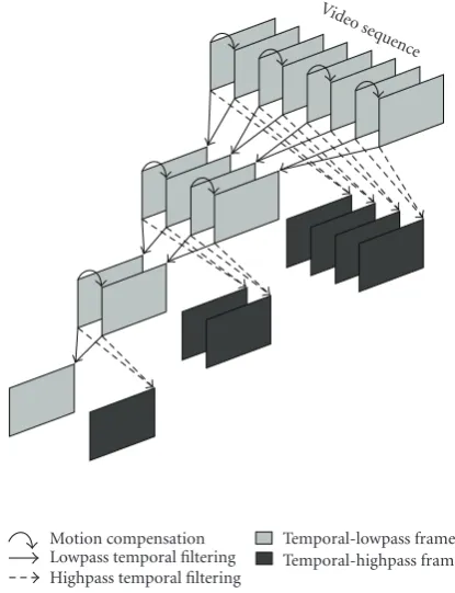
It has been recognized that a lifting3 implementation [90,91] permits the MC process in the temporal filtering to be quite general and complex while remaining easily in-verted. For example, letx1(m,n) andx2(m,n) be two consec-utive frames of a video sequence, and letWi,jdenote the op-erator that maps frameionto the coordinate system of frame
j through the particular MC scheme of choice. Ideally, we would wantW1,2[x1](m,n) ≈ x2(m,n). Haar-based MCTF would then be implemented via lifting as
h(m,n)=1
2
x2(m,n)−W1,2
x1
(m,n),
l(m,n)=x1(m,n) +W2,1[h](m,n),
(2)
where l(m,n) and h(m,n) are the lowpass and highpass frames, respectively, of the temporal transform [91]. This formulation, illustrated inFigure 12, permits any MC to be used since the lifting decomposition is trivially inverted as
x1(m,n)=l(m,n)−W2,1[h](m,n),
x2(m,n)=2h(m,n) +W1,2
x1
(m,n). (3)
The lifting implementation of the temporal filtering facil-itates temporal filters longer than the Haar [91–93], sub-pixel accuracy for ME [57,90,91,94–96], bidirectional MC and multiple reference frames [57,96, 97], multihypothe-sis MC [98–101], ME/MC using meshes rather than blocks [85,95,100,101], and multiple-band schemes that increase temporal scalability [102–104].
For coding, MCTF is combined with a 2D spatial DWT, and typically one of the 3D coders described inSection 2.1.2, such as 3D-SPIHT or JPEG2000 multicomponent, is applied to render the final bitstream. In the absence of MC, the temporal transform would be applied separately from the spatial transform, resulting in the packet decomposition of Figure 2(a). In such a case, the order in which the tempo-ral and spatial transforms were performed would not matter. However, due to the shift invariance of the spatial DWT in the presence of MC, the temporal and spatial transforms do not commute, giving rise to two broad families of MCTF ar-chitectures.
Most MCTF-based coders apply MCTF first on spatial-domain frames, following with a spatial 2D dyadic DWT. Such “t + 2D” coders have the architecture illustrated in Figure 13(a). A number of prominent MCTF-based coders (e.g., [57,88–98,105]) employ thet+2Darchitecture, includ-ing the prominent MC-EZBC coder [57]—currently largely considered to be the state-of-the-art in wavelet-based MCTF scalable coding—and its refinements [105–107]. Alterna-tively, one can reverse the transform order, applying the spa-tial transform first, and then conducting temporal filtering
3SeeSection 2.3for more on lifting in general.
Video seq uence
Motion compensation Lowpass temporal filtering Highpass temporal filtering
Temporal-lowpass frames Temporal-highpass frames
Figure12: Haar-based MCTF, depicting three levels of temporal decomposition.
among wavelet-domain frames. Such “2D+t” coders [76,99– 101,108–111] typically apply MCTF within each subband (or resolution) independently as illustrated inFigure 13(b); a spatial RDWT such as described inSection 2.2.1is often used to provide shift invariance for the wavelet-domain MCTF. Fi-nally, a hybrid “2D+t+ 2D” architecture was proposed in [86,112,113] to continuously adapt between thet+ 2Dand 2D+tstructures to reduce motion artifacts under both tem-poral and spatial scaling.
We note that the forthcoming extension to H.264/AVC for scalable video coding [114,115] uses open-loop ME/MC for temporal scalability and is closely related in this sense to MCTF. However, the remainder of the coder follows a more traditional layered approach to scalability with an H.264/AVC-compatible base layer. An oversampled pyramid, rather than a spatial DWT, is used for spatial scalability.
Input sequence
Temporal filtering
Spatial
DWT 3D coder
Output bitstream
Motion estimation
Motion vectors (a)
Input sequence
Spatial DWT
Subband 1
Subband 2
Subband 3
SubbandN
MCTF MCTF MCTF
MCTF . . .
3D coder bitstreamOutput
(b)
Figure13: (a) Thet+ 2DMCTF architecture. (b) The 2D+tMCTF architecture, with “in band” MCTF applied individually on each spatial subband. “3D coder” indicates any of the 3D wavelet-based coders fromSection 2.1.2.
standard) is proposed in [117]. In this coder, a model-based bit-allocation procedure is designed to yield a high degree of scalability.
2.2.3. Complex wavelet transforms
Although MCTF as discussed above is a relatively recent in-novation, the concept of coding video by grouping several frames together into a 3D volume and employing transforms in the spatial and temporal directions has been explored on and offin the literature for the past several decades—an early wavelet-based example is [118]. However, temporal trans-forms for video pose a unique problem that causes 3D video coding to be different from the coding of other 3D data types; MCTF is just one approach to temporally decorrelating ob-ject pixels regardless of the frame-to-frame motion they un-dergo. An alternative to MCTF has arisen recently in the form of the complexdual-tree discrete wavelet transform(DDWT) [119–121]. The DDWT is a redundant transform that, in the 3D case [121], produces four times as many subbands as the DWT, with each subband oriented in a different spatiotem-poral direction. When applied to a video signal, these ori-entations help isolate image features moving in different di-rections, providing inherent motion selectivity. The ability of the transform to describe motion without explicit ME/MC has motivated the use of the DDWT in video-coding sys-tems [58,122] looking to avoid the computational complex-ity associated with ME. However, since the 3D DDWT is four times redundant, efficient coding of the transform co-efficients is a challenging task.
In this special issue, “Video coding using 3D dual-tree wavelet transform” by B. Wang et al. as well as in preceding work [58], a DDWT-based video coder is proposed to exploit
the fact that a significant degree of correlation exists between DDWT coefficients residing at the same spatiotemporal loca-tions in different subbands. Twenty-eight-dimensional cross-subband vectors of DDWT coefficients assembled from the 28 highpass DDWT subbands are assembled and coded with arithmetic coding resulting in rate-distortion performance superior to that of 3D-SPIHT [22, 23] applied directly to a 3D DWT of the video sequence with no ME or MC. In [124], it is further recognized that large-magnitude DDWT coefficients occur rather sparsely such that small or zero coefficients tend to form spatiotemporally coherent regions within each subband. A coder is then proposed which com-bines the BISK algorithm [3,12,31], the packet transform ofFigure 2(b), and 4-dimensional cross-subband vectors of DDWT coefficients.
2.3. Image-adaptive lifting transforms
The 2D and 3D image coders discussed above rely on the DWT applied to the image data to result in coefficients hav-ing, more or less, the properties outlined at the start of Section 2.1.2. Although traditional DWTs do a reasonably good job at this task, there have been a number of efforts to improve wavelet decompositions by abandoning their fixed structure in favor of transforms that adapt to local signal characteristics. For this, an alternative transform implemen-tation is essential.
Input signal
Highpass subband
Lowpass subband +
−
LWT Prediction Update
+ +
Odd samples
Even samples
(a)
Output signal Highpass
subband
Lowpass subband
+ +
LWT−1 Prediction
Update
−
+
Odd samples
Even samples (b)
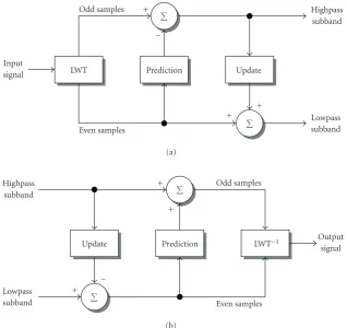
Figure14: A 1D DWT implemented via lifting. (a) The forward transform (analysis). (b) The inverse transform (synthesis). LWT is a polyphase decomposition of the input signal into even-indexed and odd-indexed samples (the “lazy wavelet transform” [123]).
into a sequence of lifting steps, typically resulting in an im-plementation with computational complexity significantly reduced as compared to the traditional convolution-based filter-bank implementation [128]. This fact alone would ac-count for widespread use in practical DWT implementa-tions; however, the lifting structure, depicted in Figure 14, permits a number of interesting generalizations to the DWT via suitably modifying the prediction or update operators. Such “second-generation” wavelet constructs include bound-ary wavelets, wavelets on irregular sampling, and wavelets that map integers to integers [17,18]; see [129] for an exten-sive overview of both first- and second-generation wavelets based on lifting.
The key to second-generation lifting formulations is that the inverse transform is trivially effectuated by simply revers-ing the operations of the forward transform, as illustrated in Figure 14(b). This fact has been exploited recently in order to devise transforms thatadaptto local signal features by modi-fying the prediction or update operations in response to local signal characteristics [130–146]. In these schemes, as long as the inverse transform can track the prediction/update vari-ations made by the forward transform, perfect reconstruc-tion is assured. Suchsignal-adaptivetransforms clearly lack shift invariance and are typically nonlinear, but often pro-duce subband signals that can be better exploited in appli-cations. Of primary interest are schemes that permit
adap-tion to take place without the need for “side informaadap-tion” between the forward and inverse transforms. Although ex-plicitly describing the adaption decisions made at the for-ward transform permits easy implementation of the inverse transform, the side information results in a transform that is, in essence, no longer critically sampled but, rather, overcom-plete.
The most common approach to adaptive lifting is based on the idea that highpass DWT subbands should be rela-tively sparse to be beneficial in most applications. As a con-sequence, the usual strategy is to design the prediction oper-ator to adapt to the signal locally so as to minimize the en-ergy in the resulting highpass subband. The update step, on the other hand, usually remains fixed, typically set to the up-date operator for some first-generation biorthogonal trans-form, such as that of the 5/3 DWT. Thisadaptive-prediction lifting strategy, employed in [130–136,146], is illustrated in Figure 15. Alternatively, in [137–145], the opposite approach of an adaptive update operator plus fixed prediction is pur-sued; in thisadaptive-updatecase, a large signal gradient pro-duces a “weak” update step such that edges and other sharp signal features are not smoothed but retain their sharpness.
Input signal
Highpass subband
Lowpass subband +
−
LWT calculationPredictor Prediction Update +
+
Odd samples
Even samples
Figure15: Adaptive-prediction lifting. Predictor is adapted to local signal features, usually in an effort to minimize energy in the highpass subband.
Figure 15, the adaption of the predictor operator is driven by the even polyphase component, and the predictor produces its prediction from the same even samples. In this manner, the predicted values, as well as the predictor itself, can be de-termined within the inverse transform. Most adaptive-lifting schemes follow this polyphase-based approach. However, the adaption of the predictor in [135,136] is driven from the highpass subband (the opposite polyphase component); this adaption is based causally on already processed highpass co-efficients such that the inverse transform can produce the same adaption. Additionally, the adaption of the update op-erator in [137–145] is driven from both polyphase compo-nents; in this case, the adaption is carefully designed mathe-matically to ensure perfect reconstruction.
In any case, the key to inversion of an adaptive lifting transform is having the inverse produce the same adaptive operator as did the forward transform. Clearly, any signal-processing operations—in particular, quantization—that lie between the forward transform and its inverse can jeopar-dize the ability to track the adaption of the operator in ques-tion. As a consequence, much of the prior literature considers only the application of lossless compression in conjunction with adaptive lifting (e.g., [132,133,144,146]). On the other hand, lossy compression can be considered if one is mindful of the consequences that quantization can entail within the adaption process of the inverse transform. For example, in [130,131], the adaptive-prediction step follows the fixed up-date step (contrary to the architecture ofFigure 15), and the adaption of the predictor is driven byquantizedsignal values; in [135], quantization is applied within the feedback loop of the causal highpass prediction update; and, in [142,143,145] conditions are determined for recovering the original adap-tion decisions at the inverse transform, and a relaadap-tion be-tween the reconstruction error and the quantization error is derived.
To this point, we have considered issues surrounding adaptive lifting of 1D signals. For 2D imagery, the typical approach is to apply a 1D adaptive-lifting scheme such as depicted inFigure 15separably to the rows and columns of the image. The 1D-based strategy can be further refined for 2D coding by enlarging the prediction (or update) context to include samples for rows/columns other than the current one [130,131,135,136]. Alternatively, a quincunx
subsam-Figure16: Quincunx subsampling. The two shades of gray indicate the two polyphase components.
pling scheme (seeFigure 16) permits lifting to be applied in a nonseparable fashion directly in 2D [133,146–149]; in this case, each lifting stage produces a single lowpass and a single highpass subband rather than the four directional subbands that arise in a separable DWT. Finally, the four directional subbands of the separable decomposition can be produced simultaneously via a single update operator combined with three prediction operators [138].
Low-resolution input signal
Prediction 2
2
DWT synthesis stage
Highpass synthesis filter
Lowpass synthesis filter
High-resolution output signal
Figure17: Wavelet-based interpolation of a 1D signal. 2D image interpolation may be accomplished by a similar system applied to the subbands of a 2D DWT synthesis stage, or by applying this 1D system in a separable fashion to image rows and columns independently.
lifting, and an application to lossless image compression is considered.
2.4. Image interpolation
Although wavelets have perhaps played their most promi-nent role in source-coding applications such as the image and video coders described above, wavelet-based signal represen-tations are widely used in other applications, such as signal filtering, denoising, feature detection, and signal enhance-ment. In particular, the multiresolution characteristic inher-ent to wavelet transforms makes them a natural choice for the task of image interpolation—the magnification or res-olution enhancement of an image with the goal of no loss to the sharpness of the image. The philosophy fundamen-tal to wavelet-based image interpolation is illustrated in 1D inFigure 17. Essentially, a highpass subband is synthesized by a prediction process from the given low-resolution signal which is, itself, treated as a lowpass subband. Both subbands then undergo a single stage of DWT synthesis, resulting in a high-resolution signal magnified by a factor of 2 as compared to the original input signal.
Although image interpolation is a classic problem in the field of image processing, traditional solutions such as bilin-ear or bicubic interpolation impose a constraint on conti-nuity in the image, resulting in a tendency to produce over-smoothed edges [152]. Additionally, these traditional inter-polators include the original image pixels in the interpolated output image, essentially making an inherent assumption that the original low-resolution input image was produced by direct downsampling of some higher-resolution image. Yet, antialiasing filters are often used in practice in image acqui-sition or resolution reduction [152]. On the other hand, the inclusion of the lowpass synthesis filter inFigure 17can be seen as compensating for the antialiasing filter (which would be the lowpass analysis filter in a nonexistent DWT analysis stage), while the predictor inFigure 17explicitly adds high-frequency information to retain sharp edge and texture de-tails.
Many wavelet-based interpolation schemes are based on the techniques originating in [153–155]. In these algorithms,
a 1D RDWT (seeSection 2.2.1) is used to determine edge lo-cations in an image row or column by identifying signal fea-tures that persist across wavelet scales in accordance with the theory of [156]. The highpass band is then synthesized by “copying” signal features from a lower-resolution subband into the new highpass band at the locations of the identified edges. The regularity of the edges is preserved by measuring the decay in regularity across scales at the edge locations and extrapolating into the newly created highpass subband. This basic strategy has been enhanced by projection onto con-vex sets (POCS, e.g., [157]) to iteratively refine the initial extrapolated highpass band [153,154]. Additionally, alter-native strategies for producing the highpass prediction were proposed in the form of linear minimum mean square esti-mation [152], hidden Markov models [158], hidden Markov trees [159], and Gaussian mixture models [160].
In this special issue, the work “Image resolution en-hancement via data-driven parametric models in the wavelet space” by X. Li adopts a POCS strategy consisting of an ob-servational constraint (DWT analysis applied to the high-resolution interpolator output must match the original low-resolution input) as well as several additional constraints on sharp highpass signal features. Specifically, separate con-straints are formulated for edges, contours, and texture fea-tures.
3. WAVELETS IN COMMUNICATIONS AND NETWORKING
error-resilient communication, and wavelets have played a role in a number of them. Below, we survey the use of wavelets in the communication and networked transmission of images and video. First, inSection 3.1, we overview pro-cedures that produce redundancy by creating multiple corre-lated codings, or descriptions, of the imagery for transmis-sion across separate network paths. Then, inSection 3.2, we overview techniques that dispense with the assumption of the separability of the source and channel design problems to develop systems in which the source and channel coders are jointly designed.
3.1. Multiple-description coding
With increasing use of the Internet and other best-effort net-works for multimedia communication, there is a growing need for reliable transmission. Traditional research efforts have concentrated on enhancing existing error-correction techniques; however, recent years have seen an alternative lution emerge and garner increasing attention. This latter so-lution focuses mainly on the situation in which immediate data retransmission is either impossible (e.g., network gestion or broadcast applications) or undesirable (e.g., con-versational applications with very low delay requirements). We are referring to a specific technique known as multiple-description coding (MDC). In this section, we overview the use of wavelets in MDC; the reader is referred to [161] for a comprehensive general review of MDC.
In essence, the MDC technique operates as illustrated in Figure 18. The MDC encoder produces several correlated— but independently decodable—bitstreams calleddescriptions. The multiple descriptions, each of which preferably has equivalent quality, are sent over as many independent chan-nels to an MDC decoder consisting of a central decoderas well as multiple side decoders. Each of the side decoders is capable of decoding its corresponding description indepen-dently of the other descriptions, producing a representation of the source with some level of minimally acceptable qual-ity. On the other hand, the central decoder can jointly decode multiple descriptions to produce the best-quality reconstruc-tion of the source. In the simplest scenario, the transmission channels are assumed to operate in a binary fashion; that is, if an error occurs in a given channel, that channel is considered damaged, and the entirety of the corresponding bitstream is considered unusable at the receiving end.
The success of an MDC technique hinges on path diver-sity, which balances network load and reduces the probability of congestion. Typically, some amount of redundancy must be introduced at the source level in order that an acceptable reconstruction can be achieved from any of the descriptions, and such that reconstruction quality is enhanced with ev-ery description received. An issue of concern is the amount of redundancy introduced by the MDC representation with respect to a single-description coding, since there exists a tradeoffbetween this redundancy and the resulting distor-tion. Therefore, a great deal of effort has been spent on an-alyzing the performance achievable with MDC ever since its beginnings [162,163] up until recently, for example, [164].
As an example of MDC, consider a wireless network in which a mobile receptor can benefit from multiple descrip-tions if they arrive independently, for example, on two neigh-boring access points. In this case, when moving between these two access points, the receiver might capture one or the other access point, and, in some cases, both. Another way to take advantage of MDC in a wireless environment is by splitting the transmission in frequency to form the two de-scriptions. For example, a laptop may be equipped with two wireless cards (e.g., 802.11a and g) with each wireless card receiving a different description. Depending on the dynamic changes in the number of clients in each network, one wire-less card may become overloaded, and the corresponding de-scription may not be transmitted. In wired networks, diff er-ent descriptions can be routed to a receiver through diff er-ent paths by incorporating this information into the packet header [165]. In this situation, the initial scenario of binary “on/off” channels might no longer be of interest. For ex-ample, in a typical CIF-format video sequence, one frame might be encoded into several packets. In such cases, the system should be designed to take into consideration indi-vidual or bursty packet losses rather than a whole descrip-tion.
Practical approaches to MDC include scalar quantization [166–168], polyphase decompositions [169,170], correlating transforms [171–177], and frame expansions [178–180]. We overview each of these strategies in the next sections below, first in the context of wavelet-based MDC for still images be-fore turning attention to MDC for video to conclude this sec-tion.
3.1.1. Multiple-description scalar quantization
Multiple-description scalar quantization (MDSQ) [166] consists of encoding a memoryless stationary zero-mean source using a separate scalar quantizer for each description. The dictionaries of the scalar quantizers are determined from the minimization of the central distortion, subject to a max-imal admissible distortion on the side distortions. Once the dictionaries are found, they must be indexed. In [166], two types of indexing are described: nested index assignment and linear index assignment. When one takes into account the rate on the two channels in addition to the distortion, the optimization problem is slightly different—in this case, the central distortion is minimized under rate as well as distor-tion constraints for the side decoders. Entropy coders follow the quantizers, and the system is called entropy-constrained MDSQ (ECMDSQ) [167]. An extension of the previous results to vectors was provided in [181–184] in the form of multiple-description lattice vector quantization.
Source
signal Encoder
Description 1
Description 2
MDC decoder Side decoder 1
Central decoder
Side decoder 2
Acceptable quality
Best quality
Acceptable quality
Figure18: MDC with two descriptions.
3.1.2. Polyphase decompositions
A polyphase decomposition provides a straightforward and relatively simple approach to achieve MDC—one first splits the source samples into polyphase components (e.g., even and odd samples) and then encodes the polyphase compo-nents independently. Recall that the M polyphase compo-nents of a sourcex[n] are the signalsy1[n],y2[n],. . .,yM[n] such that
yi[n]=x[Mn+i], n∈Z,i∈ {1,. . .,M}. (4)
In the polyphase approach to MDC, each description con-sists of a single polyphase component, and, at the decoder side, the correlation between the components is exploited to recover any lost data.
This straightforward polyphase-based MDC strategy is refined slightly in [169] wherein, after polyphase decomposi-tion, redundancy is introduced in each description by adding a low-rate version of the other polyphase components. As a consequence, each description involves a main polyphase component, encoded at high resolution, and several sec-ondary polyphase components, encoded with less rate. The decoder simply merges the received polyphase components, and, if several versions of a given polyphase component are received, the decoder makes use of only the one encoded at the highest precision. For efficient coding, the polyphase sig-nals must be decorrelated; if not, the decoder will be subop-timal, since it does not exploit the existing correlation. This system is therefore intended to be used after an initial source-coding step which consists of decorrelating the input data (e.g., a DWT or DCT).
For imagery, polyphase decompositions can be applied to different types of information in the image—pixels in the spatial domain, coefficients of a 2D DWT, or even zerotrees of wavelet coefficients (seeSection 2.1.2). In this latter scheme, odd and even zerotrees are split into two descriptions and encoded as main and secondary components using SPIHT [169,170].
It is useful to note that, whereas in most other MDC sys-tems, redundancy between the descriptions is controlled only
implicitly in the generation of the descriptions themselves, the polyphase-based MDC of [169] explicitly separates gen-eration of the descriptions from the addition of redundancy; specifically, redundancy is controlled through the bitrate al-located to the secondary components. Thus, we find, in a certain sense, a separation principle between source cod-ing (main quantization) and channel codcod-ing (added redun-dancy). While traditional source coding relies on a transform to reduce correlation between original-data (image) samples, MDC consists of the introduction of correlation in order to control redundancy in the transmitted bitstream. Below, we consider two types of correlation for the wavelet-based MDC of images—statistical correlation, through correlating transforms; and deterministic correlation, through projec-tion onto frames.
In this special issue, the work “Multiple description cod-ing with redundant expansions and application to image communications” by I. Radulovic and P. Frossard enters into the general polyphase MDC category. In the coder proposed in that work, a generic redundant dictionary is partitioned such that different, yet correlated, dictionary “atoms” are put into different descriptions.
3.1.3. Correlating transforms
A multiple-description correlating transform (MDCT) con-sists of transforming a block of N centered, independent Gaussian random variables into a block ofNcorrelated vari-ables. MDCT was introduced in [171,172] for the case of
in [175] that the optimal continuous-valued transform has the form
T=
α (2α)−1
−α (2α)−1 , (5) where the parameterα∈[σ2/2σ1,∞) allows tuning the re-dundancy,ρ,
ρ=1
2log
α2σ2
1+σ22/
4α2
σ1σ2 , (6)
whereσ2
1 andσ22 are the variances of the two sources. The discrete-valuedTtransform is then derived from (5) by fac-toring T into triangular matrices and then computing in-termediate roundings of the triangular matrix factors. One can remark that, in the case that the two variances are equal, the side distortion is constant whatever the redundancy. In fact, this distortion is the same as that obtained when send-ing each source without transformation and estimatsend-ing the missing source by the mean value in the case of a transmis-sion failure. Moreover, the side distortion does not tend to zero when the rate tends to infinity. Finally, it was concluded in [175] that MDCT appears to be more efficient for low dundancies, while MDSQ, for example, is better at higher re-dundancies.
A generalization of the MDCT strategy was proposed in [176,177]. There, an orthonormal two-band filterbank fol-lowed by different quantizers produces the correlation be-tween the two descriptions. When one of the channels is off, for example the first one, the missing symbols transmitted on this channel are linearly estimated from the decoded sym-bols on the second channel. Since the size of the filters is not restricted, this framework is more general than that of the MDCT of [175], where the size of the transform is 2×2. Ad-ditionally, in [176,177], the source is considered to be sta-tionary Gaussian of power spectrum density (psd)S(ω) in-stead of independent and identically distributed as in [175]. Consequently, in [176,177], rate-distortion theory for Gaus-sian processes (i.e., “reverse waterfilling” [185,186]) is used to determine the optimal filters. Reverse waterfilling dictates that, for a sufficiently small distortionD, the minimum rate to transmit a Gaussian process with a psd ofS(ω) is
R(D)= 1
2π π
−π 1 2log
S(ω)
D dω. (7)
This formula is used to compute the transmission rate of the Gaussian variables on each channel, supposing that the en-tropy coding achieves its theoretical limit. Moreover, an opti-mal allocation among the channels is assumed; consequently, the two descriptionsyi[n], i∈ {1, 2}, are transmitted at the rates Ri D0 = 1 2π π −π 1 2log
Yi(ω)
D0 dω
, (8)
whereYi(ω) is the psd ofyi[n], andD0is the central distor-tion. The redundancy is then
ρD0
=1 2 R1 D0 +R2
D0 − 1 2π π −π 1 2log
S(ω)
D0 dω
,
(9)
the second term corresponding to the rate-distortion curve of the sourcex[n] with psdS(ω). In case of failure on chan-nel 1,y1[n] is estimated by Wiener filtering asY21(ω)/Y2(ω), whereY21(ω) is the cross-psd of y1[n] and y2[n]. One can then compute the side distortionsD1 andD2which are ap-proximately equal to the estimation errors ofy1[n] andy2[n] by the Wiener filter. The frequency responses of the optimal filters,H1(ω) andH2(ω), are then the solution of
min H1(ω),H2(ω)
1 2
D1+D2
+λρD0
, (10)
with the central distortion fixed. The Lagrangian parameter
λalso allows adjusting the redundancy and thus the balance between central and side distortions. The following conclu-sions of this study are of interest.
(1) When λ → ∞, one simply tries to minimize the re-dundancyρ. In this case, we arrive at classical source-coding results, with the optimal filters producing decorrelated variablesy1[n] andy2[n]. The filterbank is, in this case, a Karhunen-Lo`eve transform.
(2) Whenλ=0, the redundancy is not taken into account, and one minimizes only the side distortions. The op-timal filterbank then corresponds to a polyphase de-composition, and the correlation between y1[n] and y2[n] is maximal.
(3) If the source is independent and identically distributed by blocks of 2 (i.e., vectors of two successive sam-ples are Gaussian, independent, and identically dis-tributed), the optimal filters will be FIR of length 2, and we arrive at the MDCT of [175]; this result was also shown in [187].
The work in [176, 177] also provides optimal filters for an AR(1) process and compares to classical orthonormal wavelet transforms (Haar, Daubechies, Coifman).
3.1.4. Correlation through frames
A frame is a family of vectors generating a Hilbert space; con-trary to a decomposition in a basis, frame decompositions of-ten lead to redundant coefficients. Moreover, the correlation in such a redundant decomposition is deterministic, since, for a vector space of dimensionN,N coefficients suffice to reconstruct the original signal. The redundancy permits, on the one hand, reduction of quantization noise [188], and, on the other hand, recovery after channel errors. In fact, it was shown that uniform tight frames are optimal in the case of erasures [179].
code. From this comparison, the advantage of frames occurs at high bitrate and for a very low, or very high, packet-loss rate. Otherwise, error-correcting codes are better. However, when there are no packet losses, the redundancy added by the channel code cannot be exploited, whereas frame-based redundancy can still be used by the decoder to reduce quan-tization noise.
3.1.5. MDC for video
Several directions have been investigated for video using MDC. In [189–192], the proposed schemes are largely de-ployed in the spatial domain within hybrid video coders such as MPEG and H.264/AVC; a thorough survey on MDC for such hybrid coders can be found in [193].
On the other hand, only a few works investigate MDC schemes that introduce source redundancy in the temporal domain, although this approach has shown some promise. In [194], a balanced interframe MDC was proposed starting from the popular DPCM technique. In [195], the reported MDC scheme consists of temporal subsampling of the coded error samples by a factor of 2 so as to obtain two threads at the encoder which are further independently encoded using prediction loops that mimic the decoders (i.e., two side pre-diction loops and a central prepre-diction loop).
MDC has also been applied to MCTF-based video cod-ing (seeSection 2.2.2); existing work fort+ 2Dvideo codecs with temporal redundancy addresses 3-band filter banks [196,197]. Another direction for wavelet-based MDC video uses the polyphase approach in the temporal or spatiotem-poral domain of coefficients [198–200].
In this special issue, the work “A motion-compensated overcomplete temporal decomposition for multiple descrip-tion scalable video coding” by C. Tillier et al. focuses on a two-description coding scheme for scalable video, wherein temporal and spatial scalability follow from a classical dyadic subband transform. The correlation between the two de-scriptions is introduced in the temporal domain by exploit-ing an oversampled MCTF. An important feature of the pro-posed scheme is its reduced redundancy, which is achieved by an additional subsampling of the resulting temporal de-tails. The remaining detail coefficients are then distributed in a balanced manner between the two descriptions, along with the nondecimated approximation coefficients. The global re-dundancy is thus tuned by the number of temporal decom-position levels.
3.2. Joint source-channel coding
Shannon’s separability theorem [201] states that if the min-imum achievable source-coding rate of a given source is be-low the capacity of a channel, then that source can be reliably transmitted through the channel. In addition, it states that the source and channel encoders can be separated in such a way that the source-coding rate reduction takes place in the source encoder, while the protection against channel errors occurs separately in the channel encoder—that is, source and channel coding can be treated separately without any loss of
performance for the overall system. Such a concatenation of a source coder followed by a channel coder which are sepa-rately optimized is atandemcommunication scheme. How-ever, Shannon’s separation theorem, and thus tandem com-munication, is valid only for blocks of source and channel symbols sufficiently long and for encoders and decoders of arbitrarily large complexity.
In practical situations, there are limitations on both sys-tem complexity and block length which call into question the validity of separate design. In recent decades, alternative ap-proaches consisting of combining source and channel cod-ing have arisen. The objective is to include both source- and channel-coding modules in the same processing block in or-der to reduce the complexity of the overall system while si-multaneously increasing the system performance in a non-ideal, real-world setting. Typically, efforts toward suchjoint source-channel codinghave focused on either designing chan-nel coding with respect to a fixed source—source-optimized channel coding—or on designing source coding with respect to a fixed channel—channel-optimized source coding. Below, we overview both strategies as applied to wavelet-based im-age and video source coders.
3.2.1. Source-optimized channel coding
In source-optimized channel coding, the source code is first designed and optimized for a noiseless channel. A channel code is then designed for this fixed source code so as to min-imize end-to-end distortion over a given channel (typically a binary symmetric channel (BSC), an additive white Gaus-sian noise (AWGN) channel with a given modulation, or a time-varying channel).
For example, [202] considers transmission of a video sequence over fading channels. A 3D spatiotemporal sub-band decomposition followed by vector quantization (VQ) of the subband coefficients forms the source coder, while the VQ indexes of each coded subband are interleaved and pro-tected usingrate-compatible punctured convolutional(RCPC) codes [203]. The source-coding and channel-coding rates are jointly chosen on a subband-by-subband basis to minimize the total end-to-end mean distortion. Interleaving facilitates the analytical computation of the channel-induced distor-tion by making the equivalent channel memoryless, and the optimal allocation of source- and channel-coding rates is for-mulated as a constrained optimization problem.