R E S E A R C H
Open Access
An integrated FEM-ANN model for laser
bending process with inverse estimation of
absorptivity
Ravi Kant, Shrikrishna N. Joshi
*and Uday S. Dixit
Abstract
Background:Absorption of laser energy into the worksheet surface during laser bending process is an important and critical factor for accurate computation of the bend angle. This paper presents an integrated FEM-ANN approach to compute accurate value of bend angle during laser bending process.
Methods:Initially, a finite element method (FEM) based three-dimensional nonlinear transient thermo-mechanical numerical model is developed using ABAQUS package. Using FEM model and data obtained in actual experiments, the proper values of absorptivity for various sets of process conditions are computed by inverse analysis technique. Based on the proper values of absorptivity, an artificial neural network (ANN) model is developed for accurate and quick prediction of absorptivity for given input process conditions. The predicted absorptivity is then employed in the FEM model for accurate computation of bend angle.
Results:The performance of the integrated approach is verified by conducting experiments.
Conclusion:The verification results showed that the proposed approach is able to compute the bend angle with a very good accuracy (average prediction error of 4.14 %). The proposed approach can also be suitable for the numerical simulations of other laser based manufacturing processes.
Keywords:Laser bending; Absorptivity; Inverse analysis; Bend angle; Artificial neural network (ANN); Finite element method (FEM)
Background
In laser bending process, a controlled heating of the work-sheet surface is carried out by laser beam irradiation. This induces non-uniform thermal stresses that plastically de-form the worksheet (Li and Yao 2000). The dede-formation is the result of complex interaction between laser process parameters,viz. laser power, scanning velocity and beam diameter, worksheet material properties and the work-sheet geometry. Due to uneven mechanical restraint and temperature distribution, the bend angle is not uniform along the scanning line which is called as ‘edge effect’ (Shen et al. 2010). The important features of laser bending process include absence of spring-back, possibility of forming at inaccessible areas, creation of complex shapes with different irradiation strategies, possibility of bending brittle materials and the easy control of the process (Wu et al. 2010, Kant and Joshi 2013, Kant and Joshi 2014).
Literature reports various numerical investigations on the effect of various parameters such as laser power, scanning velocity, beam diameter, sheet geometry, cool-ing conditions, number of irradiations and clampcool-ing on the process mechanism, bend angle and edge effect for a wide range of materials. Li and Yao (2000) studied the effect of strain rate by taking various combinations of laser power and scanning velocity in such a way that the peak temperature at the upper surface of the worksheet remains constant. They observed that the bend angle, re-sidual stresses and hardness decrease with increase in the strain rate. Hu et al. (2001) studied the effect of process parameters on laser bending of stainless steel. Zhang et al. (2002) developed an efficient numerical model for pulsed laser bending of full-hard 301 stainless steel. The computation time was significantly reduced by the proposed methodology. Yanjin et al. (2005) studied the effect of various thermal and mechanical properties of the workpiece material on bend angle. The bend angle
decreased with increase in Young’s modulus, yield
* Correspondence:[email protected]
Department of Mechanical Engineering, Indian Institute of Technology Guwahati, Guwahati, Assam 781039, India
strength, thermal conductivity, specific heat and density of the material while it increased with increase in the coeffi-cient of thermal expansion. Shi et al. (2006) explained vari-ous laser forming mechanisms (temperature gradient mechanism, buckling mechanism and upsetting mechan-ism) in terms of temperature and stress–strain distribu-tions. Authors proposed a new coupling mechanism based on the combination of temperature gradient and buckling mechanism. Shen et al. (2009) numerically studied the laser bending of metal/ceramic bi-layer materials sheet. Pitz et al. (2010) proposed the moving mesh methodology approach to reduce the computational time involved in the numerical simulations of laser bending process. They used a fine mesh around the laser beam and coarse mesh in the remaining part. The mesh moved synchronously with the laser beam. Jamil et al. (2011) studied the effect of laser beam geom-etries on the laser bending process governed by the buck-ling mechanism. Gollo et al. (2011) performed a statistical analysis to study the effects of material, laser power, beam diameter, scan velocity, sheet thickness, number of scans and pulse duration on bend angle.
Literarure also contains studies on the effect of forced cooling and curvilinear irradiations on the performance of laser bending. Cheng and Yao (2001) found that the forced cooling can significantly reduce the total forming time in a multi-pass laser bending process. They also found that the forced air cooling does not have any harmful effect on micro-structural and mechanical prop-erties of the workpiece. Shen et al. (2011) studied the ef-fect of forced cooling on laser bending of steel plates using finite element based numerical simulations. The forced cooling was applied either on top or bottom or on both the surfaces. It was moving simultaneously with laser beam by an offset of about one second. The forced cooling did not have a significant effect on the bend angle and edge effect. Chen et al. (2004) observed that in a curvilinear laser bending, the deformation occurs on one side of the laser scanning path along which the rigid constraint is lower. Zhang et al. (2007) showed that the peak temperature at the scanning surface and warp-ing increases with the increase in scannwarp-ing path curva-ture. Kant and Joshi (2014) observed that the worksheet does not bend over the laser scanning path in the curvi-linear laser bending process. The bend line differs from the scanning path and the bending offset increases with the increase in laser power and beam diameter.
The bend angle per laser scan is small and therefore, the laser bending is also carried out with the assistance of mechanical load. Yanjin et al. (2003) showed that pre-loading can increase the bend angle significantly. Yao et al. (2007) presented effect of various pre-loads on laser bending process. They employed pure compression, pure tension and pure bending as pre-loading and observed that pre-loading does not cause any external edge effect.
Kant and Joshi (2013) proposed a laser assisted bending with moving mechanical load for bending of large sized worksheets. Gisario et al. (2015a) studied laser assisted bending of AISI 304 stainless steel sheets of 1 mm thick-ness to obtain a large bend angle upto 140° with a small fillet radius of 2 mm. Gisario et al. (2015b) studied laser assisted origami bending of the stainless steel sheets for shaping the sheets into three dimensional items such as cubes and chairs. They found that the manufactured items have good precision, accuracy and aesthetic appearance.
A few attempts have been reported on artificial neural network (ANN) based modeling of laser bending process. Cheng and Lin (2000) used three supervised neural net-works to estimate the bend angles,viz., (1) back propaga-tion neural network (BPNN) with hyperbolic tangent function, (2) BPNN with logistic function and (3) radial basis neural network (RBFN). They found that RBFN out-performs the other two. Dragos et al. (2000) demonstrated the use of ANN in automatic control of process. Casalino and Ludovico (2002) developed an ANN model to predict the process conditions for laser bending of SAE 1020 steel sheets. Maji et al. (2014) developed an ANN model to pre-dict the process conditions for obtaining a particular dome height in three dimensional laser bending of a sheet. ANN model was able to predict the process conditions with good accuracy. Gisario et al. (2011) used neural network solutions to predict, control and manage the spring-back in laser assisted V-shape bending of thin aluminum sheets.
The review of literarture reveals that hard computing
based modeling, viz., finite element method (FEM) has
Most of the presented work considered constant ab-sorptivity for various set of process conditions. However, in real practice, the absorptivity is not constant and de-pends on various parameters such as workpiece surface condition, properties of laser beam, temperature at the irradiating surface and the properties of workpiece ma-terial. Modeling of real behavior of absorptivity during laser bending process is difficult due to complex inter-action between various parameters. In this work, an inte-grated FEM-ANN methodology for accurate prediction of laser bending for a wide range of process conditions is presented. It is assumed that the absorptivity depends on the set of laser parameters,viz.laser power, scanning velocity and beam diameter. Using FEM model, the ab-sorptivity is predicted by inverse analysis technique for various set of process conditions. The predicted absorp-tivity and the corresponding laser parameters are used to train an artificial neural network. ANN model is de-veloped to predict the absorptivity for a set of process conditions. The ANN model is integrated with the FEM model to incorporate predicted absorptivity for accurate simulation of laser bending process for a wide range of process conditions. Details of the methodology, results and discussion are presented in the next section.
Methods
Development of integrated FEM-ANN model for laser bending process
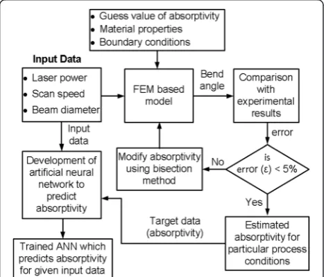
An integrated FEM-ANN methodology is proposed where absorptivity is predicted by an ANN model and is given as input to the FEM model for the simulation of laser bend-ing process. Overall approach for the development of ANN model is shown in Fig. 1. The overall approach is mainly divided into five steps;
1. At first, a finite element model is developed for laser bending of magnesium alloy M1A sheet. The finite element model is used to simulate the laser bending process for various set of process conditions. 2. In second step, numerical results are compared with
the experiments.
3. In third step, absorptivity is estimated by studying the difference between numerical and experimental results (error). A number of numerical simulations are carried out by varying the absorptivity such that the prediction error lies within an error band of ±5 %. 4. In fourth step, an artificial neural network (ANN)
model is developed to predict the absorptivity. Process parameters,viz., laser power, scanning velocity and beam diameter are considered as input data while the estimated absorptivity obtained in Step 3 is used as the target data.
5. The developed ANN model is integrated with the FEM model as shown in Fig.2. Absorptivity predicted by the ANN is used as input to the FEM model for accurate modeling of laser bending process. The proposed methodology is verified the experiments.
Development of numerical model for laser bending process
Three-dimensional nonlinear transient thermo-mechanical finite element method based numerical model is
de-veloped for the laser bending process. Coupled
thermo-mechanical analysis is carried out by employing various input process parameters such as worksheet geometry, material properties, laser process parameters and the absorptivity. The computed plastic strains are used to obtain the deformation in the work sheets. The bend angle was computed by measuring distorted coordi-nates on the deformed work sheets.The details of the nu-merical model are presented below.
Sheet geometry and material properties
The numerical model was developed for magnesium alloy M1A. It is the Mg-Mn alloy with good corrosion resistant properties. The temperature-dependent and
strain rate–dependent material properties available in
Avedesian and Baker (1999) were employed in the this work. The geometry of the sheet was taken as 60 mm length, 40 mm width and 1.90 mm thickness.
Assumptions
Thermo-mechanical modeling of laser bending process involves complex interaction between laser process con-ditions, material properties and worksheet geometry. The important assumptions considered are as follows:
The worksheet material is isotropic and homogeneous.
The worksheet is considered to be flat and free of residual stresses.
Out of the laser heat applied, the energy stored due to plastic deformation is neglected.
The von-Mises criterion is used for plastic yielding. The metals lose mechanical properties at melting
point. Therefore, stiffness of material is taken very close to zero when temperature exceeds the melting point. As such the melting needs to be avoided.
Heat flux modeling
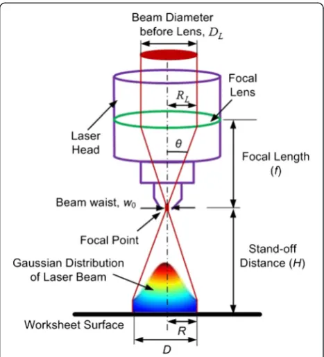
The laser beam was irradiated along a straight line at the middle of the length of workpiece at 30 mm from the free side as shown in Fig. 3. Beam diameter can be con-trolled by changing the stand-off distance between laser head nozzle and the worksheet surface. The beam diam-eter increases with the increase in the stand-off distance. The stand-off distance was converted into beam diam-eter by using standard beam propagation equations.
Figure 4 shows the schematic of laser beam path, heat flux distribution and terminologies of laser beam. The relation between stand-off distance and beam diameter can be given as (Sun 1998),
R¼w0 1þ M 2λH πw2
0
2
" #1=2
ð1Þ
where w0 (=0.05 mm) is the laser beam waist which is
the minimum beam radius at focal point of the lens, λ(=10.6μm) is CO2laser beam wavelength andHis the
stand-off distance, the distance between focal point to
the worksheet surface. M2 is the beam quality factor. The M2is equal to 1 for perfect Gaussian beam but in real practice it is always greater than 1. The theoretical value of the beam waist can be given as (Sun1998),
w0¼M 2λf
πrL ð2Þ
where rL (=12 mm) is laser beam diameter before lens. The value ofM2was calculated by puttingw0= 0.05 mm
in Equation (2) and was found to be equal to 1.4. The laser beam was assumed to be Gaussian distrib-uted circular shaped source of heat. The surface flux heat distribution q(x,y) induced by the laser beam mov-ing with a scannmov-ing velocity,V, along they direction can be defined as
q xð ;yÞ ¼AπηRP2 exp
−2ðx2þðy−V tÞÞ R2
2!
ð3Þ
whereηis the absorptivity,Pis the laser power, andRis the laser beam spot radius. The issue of absorptivity is discussed in detail in Section 'Inverse computation for prediction of absorptivity' and Section 'ANN model for estimating absorptivity'. The coefficient A decides the distribution and the magnitude of maximum heat flux inside the beam diameter. The value of A can lie be-tween 2 and 3. In this work, the value of A is taken as 2.31, which distributes the heat (ηP) within a circle of ra-dius equal to beam rara-dius.
Fig. 3Schematic of laser beam irradiation and various boundary conditions
Thermal analysis
The initial temperature of the worksheet was set equal to the room temperature. The temperature distribution was changed due to laser irradiation. The inter-convertibility of thermal and mechanical energy was ignored as heat stored due to deformation is negligible as compared with applied laser heat. Therefore, transient temperature field generated was determined by using three dimensional heat conduction equation
ρc∂∂Tt ¼∇⋅ðk∇TÞ ð4Þ
whereρ,c,T, tandkare the worksheet density, specific heat, temperature, time and thermal conductivity respec-tively.The heat loss to the surrounding occurs due to convection and radiation losses. These boundary condi-tions affect the temperature distribution. The thermal boundaries were modelled using lumped convection heat loss. The lumped convection heat loss (qc) was calcu-lated by
qc¼h Tð s−TeÞ ð5Þ
whereh= 25 W / m2−°C is the convective heat transfer coefficient,Tsis the worksheet temperature andTe= 20 °C
is the environmental temperature. The melting was in-corporated by considering the latent heat near the melting range of temperature. The solidus and liquidus temperature of the material is 648 and 649 °C respect-ively. Incorporation of latent heat in such a small range of melting temperature destabilizes the process of solv-ing the numerical problem. Therefore, latent heat was distributed over the temperature range of 645–655 °C. The latent heat of the magnesium M1A is 370 kJ/kg-°C and the distributed latent heat for the range 645–655 °C was taken as 37 kJ/kg-°C.
Mechanical analysis
The mechanical analysis was performed to get stress–
strain distribution and elastic–plastic distortions. The distortions were used to get the bend angle and edge dis-placements. The worksheet was assumed to be clamped at one side (shown in Fig. 3). The mechanical constraint, zero displacement and zero rotation, was applied at one side (clamped side) of the worksheet. The total strain and strain rate can be decomposed into elastic, plastic, creep and thermal components of strain and strain rate. How-ever, the deformation occurs at relatively short time scale and the contribution of creep can be neglected. Hence, the effect of creep was not considered. The total strain rate as a sum of elastic, plastic and thermal strain rate was given as,
_
ε˙total¼ε_˙elasticþε_˙plasticþε_˙thermal ð6Þ
Elastic strains were calculated through an isotropic Hook’s law and yielding was determined by using the von-Mises criterion which is widely accepted for the ductile materials. The von-Mises criteria can be expressed as
1
2 ðσ1−σ2Þ
2þ σ2−σ 3
ð Þ2þ σ1−σ 3 ð Þ2
¼σ2
y ð7Þ
where σy is the temperature dependent flow stress and
σ1,σ2andσ3arex,yandzstress components
respect-ively. The material properties get significantly affected
by temperature and the strain rate. Therefore,
temperature and strain rate dependent yielding was con-sidered. The strain rate dependent flow stress is given as
σy¼Cε_˙m ð8Þ
where C is the strength coefficient and m is the strain rate sensitivity exponent. The C and m are temperature dependent parameters. In mechanical analysis, the melting was incorporated by reducing the stiffness of elements after melting point of the material. The stiffness was taken near to zero at melting point. At melting point, the yield stress and elastic modulus were taken as 10−6MPa.
Solution methodology
The developed numerical model was solved by using
commercial finite element software ABAQUS™. The
worksheet continuum was discretized with three-dimensional linear hexahedron elements. These ele-ments have 8 nodes and 6 quadrilateral faces as shown in Fig. 5. In ABAQUS, three-dimensional linear
hexahe-dron eight node element ‘C3D8T’, which are specially
meant for coupled thermo-mechanical analysis were se-lected for the discretization of the worksheet. Selection of this element can provide node temperature (NT11), element temperature (TEMP), stresses, strains and dis-tortions as an output. The heated and nearby region was discretized by using uniform mesh of element size 0.5 mm and outer region was discretized by using coarse biased mesh. In the thickness direction four equidistant elements were taken. The scheme of worksheet meshing is shown in Fig. 5. The effect of mesh distortion on thermal and mech-anical analysis was taken into account. The same mesh model was used for both thermal and mechanical analyses.
prediction accuracy.However, computationally, it is not as efficient as Modified Newton method, in which some-times, convergence is not achieved (Bathe 1996). The automatic time step was selected with maximum time increment of 0.02 s. The maximum temperature change in a step was taken as 30 °C.
Experimental details
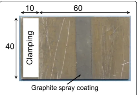
The experimental studies were performed on the com-mercially available magnesium alloy M1A sheet of thick-ness 1.9 mm. The compositions of material were 98.07 % of magnesium and 1.93 % of manganese. The specimens of 70 mm length and 40 mm width were cut using laser cutting machine. For each specimen, length 70 mm was taken along rolling direction of the sheet. Out of 70 mm, 10 mm was used in clamping and remaining 60 mm was freely hanging as a cantilever as shown in Fig. 7. The spec-imens were cleaned with cloth to remove dust and other extra particles. The metals have high reflectivity but the presence of oxides and contaminants can increase the ab-sorptivity. The oxides and other contaminants may not have uniform distribution and similar properties along the scanning length. It results in large difference in absorptiv-ity along the scanning line. Therefore, the specimens were coated with graphite spray to increase the absorptivity and also to ensure uniform absorptivity along the scanning line as shown in Fig. 6. The sprayed specimens were then allowed to dry under normal room conditions.
The specimen was clamped over the laser machine bed using a fixture as shown in Fig. 7. The laser heating was performed by using LVD Orion 3015 2.5 kW
con-tinuous wave CO2laser machine. The laser beam was
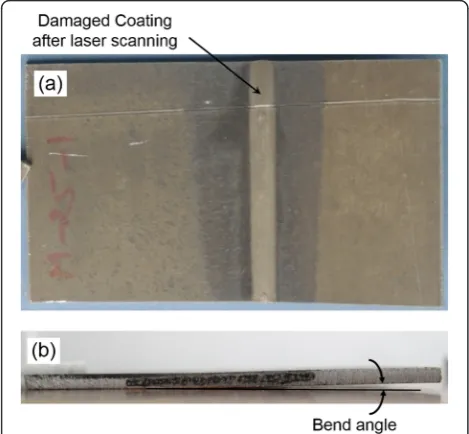
ir-radiated along the predefined path. The laser parameters laser power, scanning velocity and beam diameter were varied. Each experiment was performed with three trials to check the repeatability. The specimens were allowed to cool naturally after laser beam irradiation. Due to laser beam irradiation, the specimens were bent. By
using Zeiss made (Model: VISTA; 1620–14, DCC, BND,
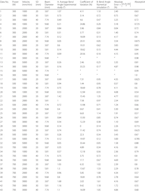
K) coordinate measuring machine (CMM), the bend angle was measured at the middle of scanning path. For a set of process conditions, the average of three trials was considered as the experimental value. Figure 8 shows laser irradiated specimen. It can be observed that due to laser heating, the coating burnt out and the worksheet bent as shown in Fig. 8a and b respectively. The experimental re-sults for various set of experiments are shown in Table 1. The coefficient of variation is calculated as the standard deviation divided by the mean of three trials. It can be ob-served from Table 1 that the coefficient of variation is high in a few cases especially when the bend angle is small. It is because when bend angle is less, a small variation results in the higher value of coefficient of variation.
Inverse computation for prediction of absorptivity Absorptivity is an important characteristic of the mater-ial which can be obtained easily by some experimental techniques usually based on spectroscopy (Stuart, 2004). A spectrophotometer can find out the ratio of reflected
Fig. 5The worksheet meshing scheme
to incident radiation for a particular wavelength, from which the absorptivity can be calculated. However, usu-ally the commerciusu-ally available spectrophotometers have provision to find out the reflectivity or absorptivity only when the specimen is at room temperature. In laser bending, a high temperature profile generates into the workpiece, which depends on the complex interaction of laser power, scanning velocity, beam geometry, number of scans, workpiece surface condition, wavelength of the laser beam, phase transformation and surrounding
conditions. It is not possible to measure the absorptivity by considering all these real-time conditions during laser bending process. In this scenario, inverse analysis is one of the best methodologies to predict the unknown pa-rameters. The use of inverse analysis to predict the un-known parameter is widely used and accepted by the research community for many real-time problems (Mis-hra and Dixit 2013, Eideh and Dixit 2013).
In general, the researchers use a constant value of ab-sorptivity for all sets and ranges of process parameters. It is a common practice in modeling and simulation of the laser bending process using physics based hard
com-puting methods viz. FEM (Hu et al. 2001, Zhang et al.
2002, Yanjin et al. 2005, Kant and Joshi 2013). This equivalent absorptivity depends on many factors such as amount of burnt coating, temperature of the surface, plasma generated, melting condition, phase transform-ation, contact time and contact area of laser beam etc. For a system, these factors depend on the set of process parameters and mainly on the laser power, scanning vel-ocity and beam diameter. Therefore, the equivalent ab-sorptivity is determined by inverse analysis technique using developed finite element model. The schematic of the inverse computation is shown in Fig. 1. The bend angle obtained from FEM model was compared with the bend angle obtained during experimental studies. The absorptivity was tuned up using a bisection method (Rao 1984) to get the FEM results within ±5 % error as com-pared with the experimental results. Finally, the tuned absorptivity was considered as the equivalent absorption for the particular set of process parameters. The pre-dicted absorptivities are shown in Table 1. It is seen that
Fig. 7Laser machine and worksheet clamping details
Table 1Bend angle and absorptivity for various process conditions
Data No. Power (W)
Velocity (mm/min)
SD (mm)
Beam Diameter (mm)
A: Average Bend Angle Experimental study (°)
Coefficient of Variation (%)
B: Bend Angle Numerical simulation(°)
Absolute Error =ðA−BA100Þ (%)
Absorptivity
1 300 1000 20 3.87 1.07 4.11 1.10 2.40 0.63
2 300 1000 30 5.81 0.73 3.14 0.72 0.75 0.67
3 300 1000 40 7.74 0.49 4.6 0.47 3.25 0.72
4 300 1000 50 9.68 0.21 24.86 0.20 3.18 0.725
5 300 2000 20 3.87 0.84 3.96 0.84 0.04 0.72
6 300 2000 30 5.81 0.31 3.77 0.31 1.40 0.74
7 300 2000 40 7.74 0.12 18.09 0.13 4.17 0.8
8 300 2000 50 9.68 0.05 29.31 0.05 3.54 0.875
9 300 3000 20 3.87 0.6 19.31 0.62 3.83 0.83
10 300 3000 30 5.81 0.14 18.62 0.15 4.44 0.84
11 300 3000 40 7.74 0.09 20.56 0.10 4.15 0.95
12 300 3000 50 9.68 a a a a 0.98
13 300 5000 20 3.87 0.26 2.46 0.25 3.35 0.81
14 300 5000 30 5.81 0.16 33.25 0.17 4.87 0.98
15 300 5000 40 7.74 a a a a 0.99
16 300 5000 50 9.68 a a a a 1.0
17 500 1000 20 3.87 0.99 7.31 0.95 4.35 0.825
18 500 1000 30 5.81 0.94 1.44 0.95 0.57 0.8
19 500 1000 40 7.74 0.75 18.69 0.78 4.11 0.6
20 500 1000 50 9.68 0.53 12.94 0.55 4.08 0.54
21 500 2000 20 3.87 1.42 15.45 1.35 4.77 0.52
22 500 2000 30 5.81 1 7.58 0.97 2.54 0.59
23 500 2000 40 7.74 0.72 13.98 0.71 1.24 0.66
24 500 2000 50 9.68 0.4 0.67 0.41 3.30 0.68
25 500 3000 20 3.87 1.27 6.63 1.14 1.91 0.57
26 500 3000 30 5.81 0.84 15.93 0.85 0.74 0.67
27 500 3000 40 7.74 0.34 12.29 0.38 1.10 0.69
28 500 3000 50 9.68 0.14 0 0.14 2.26 0.715
29 500 5000 20 3.87 0.74 11.42 0.74 0.65 0.625
30 500 5000 30 5.81 0.26 22.3 0.34 3.43 0.67
31 500 5000 40 7.74 0.12 19.97 0.12 3.00 0.785
32 500 5000 50 9.68 0.05 33.44 0.05 1.58 0.88
33 700 1000 20 3.87 0.35 4.89 0.34 4.16 0.8
34 700 1000 30 5.81 0.57 12.18 0.56 2.36 0.79
35 700 1000 40 7.74 0.75 3.75 0.72 4.51 0.8
36 700 1000 50 9.68 0.64 17.7 0.67 4.69 0.9
37 700 2000 20 3.87 1.05 6.32 1.02 2.39 0.8
38 700 2000 30 5.81 1.3 13.67 1.33 2.29 0.78
39 700 2000 40 7.74 0.96 5.85 1.00 4.34 0.57
40 700 2000 50 9.68 0.8 18.81 0.78 2.78 0.64
41 700 3000 20 3.87 1.68 2.02 1.61 4.16 0.67
42 700 3000 30 5.81 1.16 9.42 1.18 1.72 0.55
the process conditions have significant effect on the ab-sorptivity. The computed/obtained absorptivity varies from 0.50 to 1.
In order to assess the effectiveness of proposed method, a few measurements of absorptivity were car-ried out using Fourier Transform Infrared-Spectrometer (model: Spectrum BX, make: Perkin Elmer). The
nor-malized absorbance, Ab, is expressed as the common
logarithm of the ratio of incident radiation to reflected radiation. The samples were placed in the spectrometer after laser scanning was complete. The surface property may undergo some change after laser scanning; hence the comparison of computed absorptivity and absorb-ance by Spectrometer should be treated as qualitative ra-ther than quantitative. It is to be emphasized that when the measurement of absorptivity during the process is not possible, it is better to measure the absorptivity at the end of the process rather than at the beginning of the process. The measurement at the end of process will be closer to that during the process compared to meas-urement at the beginning of the process.
Table 2 shows the comparison of inversely calcu-lated absorptivity and absorbance obtained by the spectrometer. It is observed that the qualitative agree-ment between them is very good. This provides
confi-dence in the proposed methodology of inverse
estimation of absorptivity.
ANN model for estimating absorptivity
As discussed earlier, the theoretical modeling of absorp-tivity is difficult and therefore it was found convenient to develop a comprehensive absorptivity model using ANN for quick and accurate prediction. The model was
developed in MATLAB®. The inputs to the neural
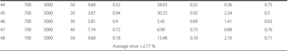
net-work were laser power, scanning velocity and beam diameter and the output was the corresponding absorp-tivity obtained by inverse analysis. Total 38 training datasets and 10 testing datasets were employed for train-ing and testtrain-ing of the ANN respectively. The traintrain-ing and testing datasets are shown in Table 3 and Table 4. The feed forward back propagation neural network (BPNN) with Scaled Conjugate Gradient (SCG) algo-rithm was used for training. The schematic diagram of BPNN with two hidden layers, one input layer and one output layer is shown in Fig. 9. A number of trials were carried out by varying the number of hidden layers and the number of neurons in each hidden layers to choose the optimal architecture. The 3–10–8–1 architecture was found to be more accurate in absorptivity predic-tion. This network has more number of parameters than the number of training datasets. Normally, the number of training datasets is more than the number of parame-ters in a model. However, the real test of the perform-ance of a neural network is made by the testing dataset. The developed ANN model is tested with 10 datasets which are shown in Table 2. By the simple analysis pre-sented in Kohli and Dixit (2005), if we assume that 80 % time the neural network predicts within the prescribed error, the probability of passing the network with 10
testing data is (0.8)10= 0.1. Thus, there is only 10 %
chance that a network which correctly predicts 80 % of the time will be passed by testing data. In other words, we can have a 90 % confidence in such a network. This is reasonable for many engineering applications. It is seen that the modeled network predicts the testing
data-set within 0.002–1.365 % of error band. The average
error is about 0.281 % and the maximum error is about 1.365 % for the selected dataset. The predicted accuracy was found to be very good for the absorptivity prediction. Thus the proposed approach can be used to predict absorptivity quickly and accurately for the given Table 1Bend angle and absorptivity for various process conditions(Continued)
44 700 3000 50 9.68 0.52 28.03 0.52 0.36 0.75
45 700 5000 20 3.87 0.94 30.25 0.92 2.24 0.5
46 700 5000 30 5.81 0.9 5.45 0.89 1.41 0.63
47 700 5000 40 7.74 0.72 6.99 0.73 0.88 0.76
48 700 5000 50 9.68 0.18 15.48 0.18 2.16 0.71
Average error =2.77 %
a
= insignificant bend angle
Table 2Comparison of inversely computed absorptivity and absorbance by spectrometer
P(W) V (mm/min)
D (mm)
Inversely calculated absorptivity
Absorbance by spectrometer
300 2000 3.87 0.72 0.727
300 1000 3.87 0.63 0.675
700 2000 9.68 0.64 0.687
700 5000 7.74 0.76 0.770
700 3000 3.87 0.67 0.690
500 3000 5.81 0.67 0.662
300 3000 3.87 0.83 0.805
input process conditions. The ANN model was further integrated with the FEM model to incorporate the process parameter dependent absorptivity for enhancement in the accuracy of the numerical simulations. The absorptivity was derived from ANN model and incorporated in the
FEM based numerical simulations for accurate process simulations.
Results and discussion
Verification of the developed FEM–ANN methodology The developed methodology is validated with the fresh
experimental results. The current FEM–ANN approach
was assessed for the effectiveness and robustness by con-ducting some verifying experiments. The verification pa-rameters were randomly selected within the range of
ANN training datasets: laser power 300–700 W;
scan-ning velocity 1000–5000 mm/min and stand-off distance
20–50 mm. The verification was done for totally new 8
datasets. For these datasets absorptivities were predicted by using developed ANN model. The predicted absorp-tivities and corresponding sets of process conditions were given as input to the FEM based model and bend angles were calculated. The calculated bend angles using current approach were compared with the bend angle obtained during experiments for the same sets of process conditions. The verification results are shown in Table 4Testing datasets
Data set No. P(W) V(mm/min) D(mm) Absorptivity
3 300 1000 7.74 0.72
8 300 2000 9.68 0.875
13 300 5000 3.87 0.81
24 500 2000 9.68 0.68
28 500 3000 9.68 0.715
30 500 5000 5.81 0.67
33 700 1000 3.87 0.8
40 700 2000 9.68 0.64
43 700 3000 7.74 0.68
45 700 5000 3.87 0.5
Table 3Training dataset
Data set No.
Power (W) Velocity (mm/min)
Beam Diameter (mm)
Absorptivity
1 300 1000 3.87 0.63
2 300 1000 5.81 0.67
4 300 1000 9.68 0.725
5 300 2000 3.87 0.72
6 300 2000 5.81 0.74
7 300 2000 7.74 0.8
9 300 3000 3.87 0.83
10 300 3000 5.81 0.84
11 300 3000 7.74 0.95
12 300 3000 9.68 0.98
14 300 5000 5.81 0.98
15 300 5000 7.74 0.99
16 300 5000 9.68 1.0
17 500 1000 3.87 0.825
18 500 1000 5.81 0.8
19 500 1000 7.74 0.6
20 500 1000 9.68 0.54
21 500 2000 3.87 0.52
22 500 2000 5.81 0.59
23 500 2000 7.74 0.66
25 500 3000 3.87 0.57
26 500 3000 5.81 0.67
27 500 3000 7.74 0.69
29 500 5000 3.87 0.625
31 500 5000 7.74 0.785
32 500 5000 9.68 0.88
34 700 1000 5.81 0.79
35 700 1000 7.74 0.8
36 700 1000 9.68 0.9
37 700 2000 3.87 0.8
38 700 2000 5.81 0.78
39 700 2000 7.74 0.57
41 700 3000 3.87 0.67
42 700 3000 5.81 0.55
44 700 3000 9.68 0.75
46 700 5000 5.81 0.63
47 700 5000 7.74 0.76
48 700 5000 9.68 0.71
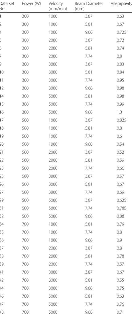
Table 5. It can be seen that the proposed FEM–ANN ap-proach have good prediction capability. During verifica-tion experiments, the bend angle was predicted within
an error range of 1.08–7.62 %. The average error was
found to be 4.14 %.
The proposed methodology is very suitable for the shop floor applications. With the development of newer materials and variation in the quality of the surface as well as coating, a handy method for the estimation of absorptivity is always useful. Even if the absorptivity data is available, it may be required to fine tune that data in real applications depending on the processing condi-tions. The main contribution of this work is to provide a suitable methodology, which can be easily employed in industrial practice. With correct values of absorptivity, FEM model can obtain the stress, strain, strain-rate and temperature distribution. This also helps in developing microstructural model for the process.
Conclusions
In this work, an FEM–ANN based integrated approach
is developed for accurate computation of bend angle during laser bending process. Initially three-dimensional nonlinear thermo-mechanical FEM based numerical model is developed for computation of bend angle for given process conditions. The absorptivity used in the numerical model was then tuned by using inverse analysis technique. In this technique, FEM simulations were repeated by varying the values of absorptivity. The value of absorptivity for each set of process condition was estimated by comparing the bend angle obtained in the numerical and experimental studies so that the com-putational error of bend angle is less than 5 %. Based on the estimated values of absorptivity and the correspond-ing input process conditions, an ANN based model was developed for fast and accurate prediction of absorptiv-ity. Then, the ANN based absorptivity was employed in the FEM model for computation of bend angle. Within
the scope of process conditions used in the present work, the proposed approach was found to be accurate in the computation of bend angle with an average error of 4.14 %. The estimated absorptivity is a fitting param-eter as it serves the purpose of correctly estimating the bend angle. However, it also matches qualitatively with the experimentally determined absorbance. This ap-proach can be used for accurate computation of process responses in the other laser based manufacturing pro-cessesviz. laser welding, laser machining, etc.
Competing interests
The authors declare that they have no competing interests.
Authors’contributions
All authors contributed extensively to the work presented in this paper. They all together conceived the strategies, formulated the problem and designed layout of the work. All authors discussed the results and implications as well as commented on the manuscript at all stages.Ravi Kant conducted the experiments and numerical simulations. S. N. Joshi and U. S. Dixit gave their ideas, suggestions and helped in the analyses of results during this course of work. The first draft of the manuscript was written by Ravi Kant. S. N. Joshi and U. S. Dixit carried out some important modifications to improve the final draft of the manuscript. All authors read and approved the final manuscript. All authors take the responsibility for the paper and there is no honorary author here.
Authors’information
Dr. U.S. Dixit obtained a bachelor’s degree in mechanical engineering from erstwhile University of Roorkee (now Indian Institute of Technology Roorkee) in 1987, MTech in mechanical engineering from Indian Institute of Technology (IIT) Kanpur in 1993, and PhD in Mechanical Engineering from IIT Kanpur in 1998. He has worked in two industries—HMT Pinjore and INDOMAG Steel Technology, New Delhi, where his main responsibility was to design various machines. Dr. Dixit joined the Department of Mechanical Engineering, Indian Institute of Technology Guwahati, in 1998 where he is currently a professor. He was the Officiating Director of Central Institute of Technology, Kokrajhar from Febuary 2014 to May 2015. He is actively engaged in carrying out research in applied plasticity for the last 23 years. Dr. Dixit has published about 63 journal papers, 72 conference papers, and 5 books related to manufacturing and finite element method. He has also edited three books related to metal forming and laser based manufacturing. He has guest-edited a number of special issues of journals and is currently an associate editor in the Journal of Institution of Engineers (India) Series C. He has guided 5 doctoral and 40 masters’students.
Dr. Shrikrishna N. Joshi has completed his doctoral studies in the area of
“Intelligent modeling and optimization of electric discharge machining Table 5Results of verification experiments
S. No. Power (W) Velocity (mm/min)
SD (mm) Beam diameter (mm)
ANN predicted absorptivity
Computed bend angle with the numerical model (°)
Average value of bend angle in Experiments (°)
Error in bend angle (%)
1 650 2000 45 8.710 0.638 0.856 0.816 4.90
2 500 2500 30 5.807 0.648 0.885 0.863 2.55
3 450 4500 30 5.807 0.847 0.473 0.512 7.62
4 400 3500 35 6.775 0.86 0.314 0.305 2.95
5 600 1500 35 6.775 0.773 1.189 1.202 1.08
6 350 3000 40 7.743 0.938 0.179 0.171 4.68
7 700 4000 20 3.872 0.551 1.546 1.469 5.24
8 500 3500 50 9.678 0.777 0.109 0.118 7.62
process”from IIT Bombay in
the year 2009. Since then he is working as an Assistant Professor in the Department of Mechanical Engineering, IIT Guwahati. His research interests are Micro-machining and Micro-bending using Lasers; Computer aided design and manufacturing (CAD/CAM); Manufacturing process modeling and optimization; and Mechatronics. He teaches undergraduate/graduate courses on Micro-manufacturing; Mechatronics and Manufacturing Automation, CAD/CAM; and Manufacturing Technology. He has completed a sponsored project on“Experimental characterization of single spark EDM process” sponsored by IIT Guwahati. Right now he is pursuing a research project on“Improving productivity and product quality during thin wall milling operations”sponsored by Department of Science and Technology, Govt. of India. He is guiding five PhD students who are working on various research areas such as Laser bending, Laser induced plasma micro-machining, Thin-wall milling and single point diamond turning. Dr. Joshi has about 30 papers published in international journals and conferences of national/international reputes.
Ravi Kant is a research scholar in the Department
of Mechanical Engineering, Indian Institute of Technology Guwahati, India. He is pursuing his doctoral studies in the area of‘Laser Bending Process’. He completed his post-graduation from IIT Guwahati and worked in the area of 'Formability of Adhesive Bonded Blanks'. His research interests include laser based manufacturing, sheet metal forming, material testing etc. He has published about 20 papers in international journals and conferences of national/international reputes.
Acknowledgements
Partial funding from the Engineering and Physical Sciences Research Council (UK) through grant EP/K028316/1 and Department of Science and Technology (India) through grant DST/RC-UK/14-AM/2012, project Modeling of Advanced Materials for Simulation of transformative Manufacturing Processes (MAST) is gratefully acknowledged. The 2.5 kW CO2Laser Cutting
Machine was purchased under DST_FIST scheme of Department of Science and Technology, India (Sanction no. SR/FST/ETI-244/2008, Date: 17.03.2009).
Received: 19 March 2015 Accepted: 8 October 2015
References
Avedesian MM, Baker H (1999) Magnesium and magnesium alloys, 2nd edn. International, ASM
Bathe KJ (1996) Finite element procedures. Prentice Hall of India Pvt. Ltd., New Delhi
Casalino G, Ludovico AD (2002) Parameter selection by an artificial neural network for a laser bending process. Proceedings of the Institution of Mechanical Engineers, Part B. J Eng Manuf 216:1517–1520
Chen D, Wu S, Li M (2004) Deformation behaviours of laser curve bending of sheet metals. J Mater Process Technol 148:30–34
Cheng J, Yao Y (2001) Cooling effects in multiscan laser forming. J Manuf Process 3:60–72
Cheng P, Lin S (2000) Using neural networks to predict bending angle of sheet metal formed by laser. Int J Mach Tool Manuf 40:1185–1197
Dragos V, Dan V, Kovacevic R (2000) Prediction of the laser sheet bending using neural network. International symposium on Circuits and systems, Geneva, Switzerland, pp III–686–III–689
Eideh A, Dixit US (2013) A robust and efficient inverse method for determining the thermal parameters during laser forming. Proceedings of National Conference of Recent Advancements in Mechanical Engineering. NERIST, Nirjuli, India, pp 38–43.
Gisario A, Barletta M, Conti C, Guarino S (2011) Springback control in sheet metal bending by laser-assisted bending: Experimental analysis, empirical and neural network modelling. Opt Lasers Eng 49:1372–1383
Gisario A, Barletta M, Venettacci S, Veniali F (2015a) Laser-Assisted Bending of Sharp Angles With Small Fillet Radius on Stainless Steel Sheets: Analysis of Experimental Set-Up and Processing Parameters. Lasers in Manufacturing and Materials Processing 2:57–73
Gisario A, Barletta M, Venettacci S, Veniali F (2015b) External force-assisted LaserOrigami (LO) bending: Shaping of 3D cubes and edge design of stainless steel chairs. J Manuf Process 18:159–166
Gollo MH, Mahdavian SM, Moslemi NH (2011) Statistical analysis of parameter effects on bending angle in laser forming process by pulsed Nd: YAG laser. Journal of Optics and Laser Technology 43:475–82
Hu Z, Labudovic M, Wang H, Kovacevic R (2001) Computer simulation and experimental investigation of sheet metal bending using laser beam scanning. Int J Mach Tool Manuf 41:589–607
Jamil M, Sheikh M, Li L (2011) A study of the effect of laser beam geometries on laser bending of sheet metal by buckling mechanism. Opt Laser Technol 43:183–193
Kant R, Joshi SN (2013) Finite element simulation of laser assisted bending with moving mechanical load. International Journal of Mechatronics and Manufacturing Systems 6:351–366
Kant R, Joshi SN (2014) Numerical modeling and experimental validation of curvilinear laser bending of magnesium alloy sheets. Proceedings of the Institute of Mechanical Engineering Part B. J Eng Manuf 228:1036–1047 Kohli A, Dixit US (2005) A neural-network-based methodology for the prediction
of surface roughness in a turning process. Int J Adv Manuf Technol 25:118–129 Rao SS (1984) Optimization: theory and applications, 2nd edn. Wiley Eastern Ltd,
New York
Li W, Yao Y (2000) Numerical and experimental study of strain rate effects in laser forming. J Manuf Sci Eng 122:445–451
Maji K, Pratihar DK, Nath AK (2014) Laser forming of a dome shaped surface: Experimental investigations, statistical analysis and neural network modeling. Opt Lasers Eng 53:31–42
Mishra A, Dixit US (2013) Determination of thermal diffusivity of the material, absorptivity of the material and laser beam radius during laser forming by inverse heat transfer. Journal of Machining and Forming Technologies 5:207–226
Pitz I, Otto A, Schmidt M (2010) Simulation of the laser beam forming process with moving meshes for large aluminium plates. Phys Procedia 5:363–369 Shen H, Hu J, Yao Z (2011) Cooling effects in laser forming. Mater Sci Forum
663–665:58–63
Shen H, Hu J, Yao Z (2010) Analysis and control of edge effects in laser bending. Opt Lasers Eng 48:305–315
Shen H, Yao Z, Hu J (2009) Numerical analysis of metal/ceramic bilayer materials systems in laser forming. Comput Mater Sci 45:439–442
Shi Y, Yao Z, Shen H, Hu J (2006) Research on the mechanisms of laser forming for the metal plate. Int J Mach Tools Manuf 46:1689–1697
Stuart BH (2004) Infrared Spectroscopy: Fundamentals and Applications. John Wiley & Sons, West Sussex
Sun H (1998) Thin lens equation for a real laser beam with weak lens aperture truncation. Opt Eng 37:2906–2913
Wu D, Zhang Q, Ma G, Guo Y, Guo D (2010) Laser bending of brittle materials. Opt Lasers Eng 48:405–410
Yanjin G, Sheng S, Guoqun Z, Yiguo L (2003) Finite element modeling of laser bending of pre-loaded sheet metals. J Mater Process Technol 142:400–407 Yanjin G, Sheng S, Guoqun Z, Yiguo L (2005) Influence of material properties on the laser-forming process of sheet metals. J Mater Process Technol 167:124–131 Yao Z, Shen H, Shi Y, Hu J (2007) Numerical study on laser forming of metal
plates with pre-loads. Comput Mater Sci 40:27–32
Zhang P, Guo B, Shan D, Ji Z (2007) FE simulation of laser curve bending of sheet metals. J Mater Process Technol 184:157–162
Zhang X, Chen G, Xu X (2002) Numerical Simulation of Pulsed Laser Bending. J Appl Mech 69:254–260
Submit your manuscript to a
journal and benefi t from:
7 Convenient online submission
7 Rigorous peer review
7 Immediate publication on acceptance
7 Open access: articles freely available online
7 High visibility within the fi eld
7 Retaining the copyright to your article