R E S E A R C H
Open Access
Non-destructive inspection on anchorage
defect of hollow grouted rock bolt using
wavelet transform analysis
Yang Hao
1, Yu Wu
1,2*, Pan Li
1, Jing Tao
1, Yi Teng
2and Guan Hao
2Abstract
Hollow grouted rock bolts are widely used in deep soft rock roadways. The density of grout has a significant influence on the anchorage quality. However, there is still a lack of effective methods to detect the grouting quality fast, accurately, and extensively. Based on the wave velocity and the law of stress wave transmission and reflection in the impedance mismatch, non-destructive experiment focused on the defect in the anchorage was conducted. The wavelet transform was used to analyze the test signals. The test results show that the free length of hollow grouted rock bolt could be accurately detected through the analysis of the stress wave signal by using the low-pass filter in the wavelet toolbox. The grouted length, defect length, and specific position of the anchorage section can be accurately detected through the analysis of the stress wave signal by using the high-pass filter in the wavelet toolbox. The research can provide experiment foundation for further study of grouting quality based on the non-destructive methods.
Keywords: Hollow grouted rock bolt, Anchorage quality, Wavelet transform, Non-destructive inspection
1 Introduction
With massive coal mines entering the stage of deep min-ing, many new issues come out and the reinforcement of soft surrounding rock mass of roadways is one of those problems. The main issues of reinforcing deep soft rock roadways include high field stress, high temperature, and high water content [1–4], thus lead to a loose and broken surrounding rock. Hollow grouted rock bolts can be employed to improve the mechanical properties of the surrounding rock mass and also provide anchorage in soft rock roadways due to their convenience and fast installation. Hollow grouted rock bolt has middle hollow tube design. The middle hollow tube of the rock bolt is used as the high-pressure blast channel and grouting channel. Compared with conventional rock bolts with the same cross-section area, the hollow design can make the rock bolts have better stiffness and shear strength [5]. The external surface of this bolt has threads with
large thread pitch. The thread structure is convenient for cutting and lengthening. Compared with smooth rock bolts, the bonding area between the rock bolt and the grouting material is improved, and therefore, the load bearing capacity is improved. Several researches show that the anchorage quality of the grouted rock bolt is influenced by shear stress on the interfaces between the rock bolt, the grout, and the surrounding rock mass [6–9]. The shear stress mainly relies on the mechanical property of the grouted rock bolt, the bond on the inter-face, and the compaction rate of the surrounding rock mass after grouting [10]. Several researchers studied the anchorage quality based on theoretical analysis and physical research, providing basis and reference for the design of grouted rock bolts [11,12]. However, in engin-eering, detecting the anchorage quality still mainly relies on pullout tests [13]. The limits are that the examination area is narrow and it cannot reflect the whole anchorage quality of the rock mass. Furthermore, pullout tests can ruin the rock bolting system. The mining engineering aims at the digital mining and green mining in the fu-ture [14]. Non-destructive detecting technology has the advantages of intelligence, rapidness, and large area * Correspondence:[email protected]
1
State Key Laboratory for Geomechanics and Deep Underground Engineering, China University of Mining and Technology, Xuzhou 221116, China
2School of Mechanics And Civil Engineering, China University of Mining and Technology, Xuzhou 221116, China
detecting. Therefore, this method can be used to study the anchorage quality of hollow grouted rock bolts.
There are many theoretical analysis, experimental re-search, and engineering applications regarding the non-destructive detecting of the anchorage quality of conventional rock bolts. The Gendynamik AB Company proposed the non-destructive detecting instrument for rock bolts. This instrument detects the loss of ultrasonic energy to determine the defect length of rock bolts. However, the ultrasonic energy decays quickly along the rock bolt. Furthermore, the operating process is compli-cated, requiring a high environment condition. Conse-quently, this method is not widely used [15]. Beard MD developed the GRANIT equipment, based on the ultra-sonic wave propagation along the grouted rock bolt after it is anchored. However, the numerical model is simple and there was a significant difference between experi-mental results and numerical results [16, 17]. In recent years, Madenga and Zou studied the influence of excita-tion frequency on rock bolt length and anchoring defect level based on theoretical analysis, numerical simulation, and experiments. The wave amplitude ratio was used to analyze the corresponding relationship of the excitation frequency and waveform character of the rock bolt with free length and grouted length [18–20]. Li et al. used the hammer impact method to study the length of the fully grouted rock bolt and grout ratio, establishing the rela-tionship between the grout ratio and waveform character [21]. Zhang et al. used the acoustic wave non-destructive detecting method. Specifically, statistics and regression analysis were adopted to study the grout ratio and wave-form character [22]. Zhu et al. studied the grout ratio based on the waveform character of the high frequency of stress wave in the grouted length of the rock bolt [23]. Sun et al. conducted waveform analysis to study rock bolts with different defect lengths, based on the low strain and stress wave reflection method. Further-more, several measuring points were set along the rock bolt, and wavelet transform was used to analyze the wave velocity in different anchoring media, acquiring ac-curate defect positions and rock bolt length [24].
Overall, the research objects of non-destructive detect-ing technology and principle are conventional rock bolt; little research has been conducted on the non-destructive detecting of the hollow rock bolts used in deep soft rock roadway reinforcement. The main differ-ence of conventional rock bolt and hollow rock bolt is the center hollow design of hollow rock bolt, which could result in the different propagation character. Therefore, in this paper, based on the hammer method used in the non-destructive detecting technology and the wavelet transform analysis, the rock bolt free length, the grouted length, the defect length, and their positions were experimentally studied.
2 Methods and experiment
2.1 Theory background
2.1.1 Stress wave propagation in hollow grouted rock bolt
Conventional hollow grouted rock bolt has a diameter of 25–32 mm, and the length is ranged from 2 to 10 m. Therefore, for simplification, the anchoring body com-posed of the rebar and the grout can be regarded as a 1D rod [25, 26]. The horizontal inertial effect can be neglected, and the planar interface assumption was used. According to the small strain theory, at the external end of the hollow rock bolt, if a hammer was used to create an initial excitation along the longitudinal direction of the rock bolt, the bar mass point can generate tensile and compressive elastic stress wave. And the wave propagates in the form of the longitudinal wave. The propagation process includes the characters of wave propagation, transmission, and reflection. Therefore, be-fore the experimental study, it is necessary to conduct theoretical analysis on the propagation character.
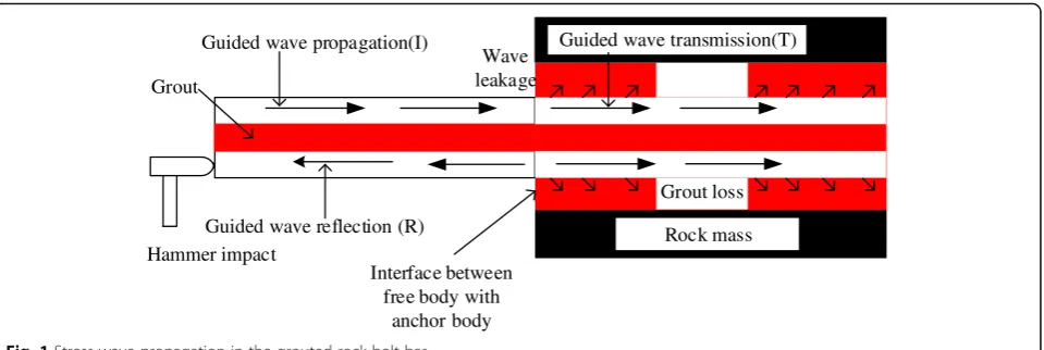
When the longitudinal elastic stress wave propagates on the interface between different wave impedance, transmission and reflection can occur in the elastic wave, as shown in Fig.1.
Due to the continuity condition of the displacement, force, and velocity at the interface, the following equa-tions can be acquired [27]:
Displacement boundary:
U1¼U2; UIþUR¼UT ð1Þ
whereU1andU2are the displacement of the stress wave
in the free section of rock bolt; UI,UR, andUTare the
displacement of wave propagation, wave reflection, and wave transmission, respectively.
Velocity boundary:
V1¼V2; VIþVR¼VT ð2Þ
where V1 and V2are propagation velocity of the stress
wave in the free section of rock bolt, respectively;VI,VR,
VTare the velocity of wave propagation, wave reflection,
wave transmission, respectively.
Force boundary:
N1¼N2 NIþNR ¼NT ð3Þ
whereN1andN2are the force of the stress wave in the
free section of rock bolt;NI,NR, andNTare the force of
wave propagation, wave reflection, wave transmission, respectively.
According to the wave equation and boundary con-straint conditions, the reflection coefficient and trans-mission coefficient can be acquired respectively:
εR¼ðZ2−Z1Þ=ðZ2þZ1ÞεT ¼2Z2=ðZ2þZ1Þ: ð4Þ
defined as the ratio of the wave impedance. ρ1 is the
density of the rock bolt-free section;A1is the cross area
of the rock bolt-free section; ρ2 is the density of the
whole grouted section; and A2 is the cross area of the
whole grouted section.
Therefore, whenZ2>Z1, the wave propagates from the medium with low impedance to the medium with large impedance and the reflection coefficient is negative. The wave sign will have a reverse mutation. When Z2<Z1, the wave propagates from the medium with large imped-ance to the medium with small impedimped-ance and the re-flection coefficient is positive. The wave sign does not have a mutation. For example, when the stress wave propagation reaches the interface between the free length and the grouted length, the reverse impedance can occur in the reflected wave. Transmission wave will continue to propagate to the basement. When it reaches the basement, the wave impedance of the grouted sec-tion is larger than the wave impedance of the air. And the reflected wave will not have a mutation.
Based on the propagation principle of the elastic stress wave in the 1D bar, the wave equation can be established [27]:
∂2μ
∂t2−C 2∂2μ
∂x2¼0 ð5Þ
where μis the displacement of a point along the direc-tion ofx[mm]; tis the propagating time of the wave in the bar [us];Cis the propagation velocity of the longitu-dinal wave in the composite bar,C2=E/ρ[m/s]; andEis Young’s modulus [GPa]; ρ is the bar density [kg/m3]. Compared with metal rock bolts, the hollow grouted rock bolt is a composite medium composed of steel bar and ce-ment grout. The density of those two rock bolts is ranged in the same order of magnitude. However, Young’s modu-lus of the traditional rock bolt is much larger than the hol-low rock bolt. Consequently, it is analyzed that the wave
velocity of the elastic stress wave in the hollow rock bolt is smaller than the metal rock bolt.
2.1.2 Wavelet transform
The stress wave propagation in the hollow grouted rock bolt is rather complicated. Consequently, the signal ana-lysis method should be conducted to accurately extract the reflection character points at each end face. The ap-plication of conventional signal processing methods such as fast Fourier transform (FFT) does not always give a good performance because of the accuracy and the large sample size of signals, which requires a space memory. Furthermore, they have a fixed length of the window, and they cannot be used in a transient state. Wavelet transform provides information about a signal that a Fourier transform or short time Fourier transform has difficulty in extracting because the wavelet analysis is a localized transform in the time or frequency domains. The main advantage of this method is the described flexibility in the non-stationary states signals. In addition, wavelets are largely oscillating functions that are rapidly damped, unlike the sinusoidal functions of Fourier analysis. In this paper, wavelet transform was used to analyze the collected signals. In the wavelet transform, the original signal was decomposed as signal
Aand signal D. Arepresents the approximate part. It is the coefficient generated by the low-pass filters, represent-ing the low-frequency component of the signal.D repre-sents the detailed value. It is the coefficient generated by the high-pass filters, representing the high frequency com-ponent. In many signal analysis, the low-frequency section is most significant. It is optimization regarding the whole signals with the noisy part. Based on the conclusion that stress wave with low frequency is sensitive to the free end of rock bolts, low-frequency analysis can be conducted on signals to acquire the character points of the interface be-tween the free part and the anchorage part. High-frequency section is conducting detailed analysis on the Guided wave propagation(I)
Guided wave reflection (R) Grout
Interface between free body with
anchor body Grout loss Rock mass Hammer impact Wave leakage
Guided wave transmission(T)
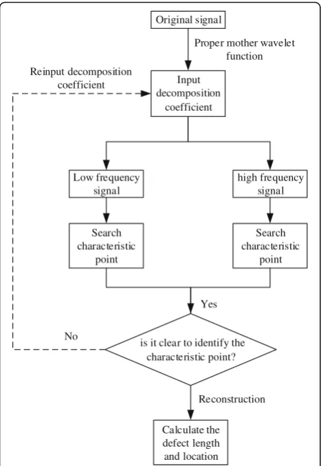
local signals, having the function of “microscope” [16]. Therefore, high-frequency analysis was conducted on the anchorage part to acquire character points in the end of anchorage and defect position, the hollow grouted rock bolt length, and the defect positions. The distinguishing flowchart is shown in Fig.2.
2.2 Experiment
2.2.1 Specimen preparation
Based on the theory background, the velocity of the free and grouted part are the two important parameters to cal-culate the length and defect of rock bolts. Therefore, three hollow grouted rock bolts without anchorage were used to evaluate the velocity in rebar with the number of 1#, 2#, and 3#, respectively. Then, three hollow grouted rock bolts with anchorage of bad quality, qualification, and good quality were prepared to study the different defect in anchorage part. Note that the grout ratio, defined as the length of the defect to the length of anchorage, is a meas-urement standard to evaluate the anchorage quality. Three hollow grouted rock bolts with 50%, 75%, and 100% num-bered as 4#, 5#, and 6#, respectively, were prepared based on the specifications for bolt-shotcrete support in national standard GB50086—2001, in which declares that over 75% of the anchorage density are qualified [28]. It should be noted that the definition of anchorage density is the per-centage of solid volume in core volume extracted in over-coring test [29].
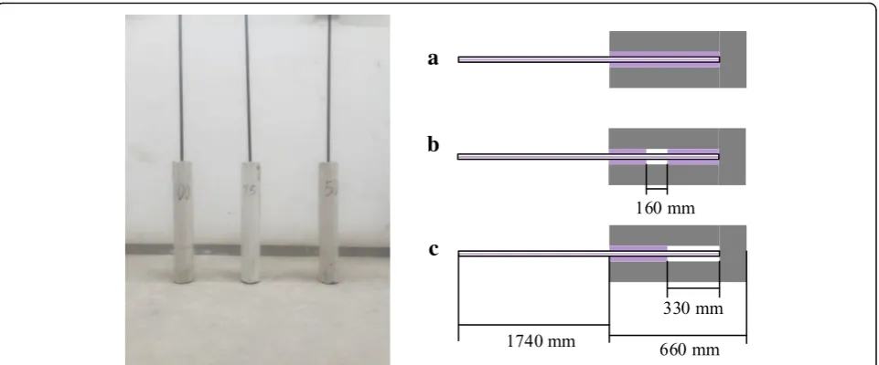
The specific procedure of specimens 4#, 5#, and 6# was as follows. Concrete materials were poured into PVC pipes with a diameter of 160 mm and a length of 1000 mm to simulate the surrounding rock mass. The concrete is composed of 32.5# Portland cement, fine gravels, and water. The mass ratio between the cement, water, and gravel is 1:2:3. Meanwhile, PVC pipes with a diameter of 50 mm and a length of 1000 mm were fixed in the center of the surrounding rock to simulate the drilling process in the hollow rock bolt installation. Be-fore the concrete cured, PVC pipe with a diameter of 50 mm was pulled out, and then, the concrete cured for 28 days. Foamed plastics were used to bundle two hollow rock bolts with a diameter of 25 mm to simulate the ungrouted section. The position and length of defect were shown in Fig. 3. Then, a hollow rock bolt and a rock bolt bundled with foamed plastics were fixed in the
Fig. 3The schematic diagram of the defect length and the position
Yes
No
Reinput decomposition coefficient
Original signal
Input decomposition
coefficient
Low frequency signal
high frequency signal
Search characteristic
point
Search characteristic
point
is it clear to identify the characteristic point?
Calculate the defect length and location
Proper mother wavelet function
Reconstruction
center of the borehole. A grouting pump was used to in-ject the cement-based grout until the grout overflowed the borehole. After the grout fully cured, the sample was ready for testing. Due to the installation requirement of pullout test machine in next experimental research of different load at hollow rock bolts, the free length of hollow rock bolts in this experiment is longer than the one used in the on-site application. However, it has no influence on the non-destructive detect results deter-mined by velocity in free and grouted part. The sche-matic diagram of the samples is shown in Fig.4, and the geometric parameters are tabulated in Table1.
2.2.2 Experimental equipment and method
Non-destructive detect equipment [27] developed by our research group was used to collect data. The equipment is mainly composed of three parts, piezoelectric trans-ducer, vibration generator, and non-destructive detect instrument. The specific parameters of the piezoelectric transducer and the non-destructive detect instrument can be found in Reference [27]. Based on theoretical analysis, low-frequency excitation is beneficial for
eliminating dispersion and diffusion. Therefore, accord-ing to the current research results of non-destructive de-tect vibration exciter, the frequency of the stress wave generated by the hammering method is ranged between 5 and 15 kHz. Therefore, an excitation hammer shown in Fig.5was used to conduct the experiment to study its excitation effect.
The experiment was mainly composed of two proce-dures: signal collecting and analysis. First, the signals should be collected. The sensor was placed at the front end of the hollow grouted rock bolt. The hammer was used to impact the rock bolt front end, generating the stress wave which propagates along the axial direction of the rock bolt. The non-destructive detecting instrument was used to record the stress wave propagation and re-flection signals. Finally, the collected signals were imported to the computer, and the wavelet transform method was used to analyze the recorded signals.
The specific procedures are listed as follows: first, data recording was conducted regarding the samples tabu-lated in Table 1, and signals of s1,s2, and s3 can be ac-quired. Then, the propagation character of the elastic stress wave in the unhollow grouted rock bolt was
Table 1The geometric parameters of the samples
Sample number Hollow rock bolt length (mm)
Hollow rock bolt diameter (mm)
Grouted length (mm) Free length (mm) Defect length (mm) Grout ratio (%)
1# 2400 25 ~ ~ ~ ~
2# 2400 25 ~ ~ ~ ~
3# 2400 25 ~ ~ ~ ~
4# 2400 25 660 1740 0 50
5# 2400 25 660 1740 160 75
6# 2400 25 660 1740 330 100
a
b
c
a
b
Fig. 6The sociogram of the hollow grouted rock bolt exposed in the air after grouting (a). The original signal ofs1,s2, ands3(b) low-frequency
decomposition by 5 scale ofs1,s2, ands3
Transducer Hammer Signal collector
analyzed. After that, data recording was conducted on the fourth sample, and a signal of s4 can be acquired. Based on the known grouted length, the propagation velocity and character of the elastic stress wave in the grouted length can be analyzed. Then, data recording was conducted on the fifth and sixth samples, and the signals of s5 and s6 can be acquired. The propagation and reflection character of the elastic stress wave in the grouted length having defects were analyzed.
3.1 Determination of the wave velocity in the hollow grouted rock bolt
To analyze the free length, grouted length, defect length, and defect position of samples 4#, 5#, and 6#, the elastic stress wave velocity in the free length and grouted length should be acquired. Signals of s1,s2, and s3 should be analyzed to evaluate the wave velocity of the free length and the defect length. Through a large number of at-tempts, low-frequency pass filters with 5 scale were con-ducted on the signals ofs1,s2, ands3 to obtain the best oscillogram, as shown in Fig.6. The propagation time of the wave in the rock bolt can be calculated based on the “peak-to-peak value” theory. Then, based on the rock bolt length, the elastic stress wave velocity along the hol-low grouted rock bolt can be calculated. The specific pa-rameters are tabulated in Table2.
a
b
Fig. 7Waveform diagram of low-frequency analysis for samples 4#, 5#, and 6#. (a) Original signal of sample 4#, 5#, and 6#. (b) Low-frequency decomposition by 5 scale of 4#, 5#, and 6#
Sample number
Propagation time (us)
Sample length (mm)
Wave velocity (m/s)
1 1082 2400 4436
2 1075 2400 4465
It can be seen that the propagation velocity of the stress wave in the rock bolt exposed in the air is ranged between 4247 and 4465 m/s. Considering the error between the signal intercept points, it is deter-mined that the propagation velocity of the elastic stress wave in the free length and ungrouted length was set at 4356 m/s. However, in traditional steel rock bolts, the propagation velocity of the stress wave is ranged between 5180 and 5200 m/s [30]. Comparing
the different structural characters of those two rock bolts, it can be concluded that the grout delayed the elastic stress wave propagation in hollow grouted rock bolts. The experimental results were consistent with the theoretical analysis.
For the wave velocity in the grouted length, the propa-gation time of the stress wave in the free length and grouted length should be distinguished, and it can be ac-quired in the following analysis.
Fig. 8The high-frequency signal analysis waveform of sample 4# (unit: mm)
Table 3Statistical table of the hollow grouted rock bolt free length for samples 4#, 5#, and 6#
Sample number Wave velocity (m/s) Propagation time (us) Theoretical length (mm) Calculated length (mm) Error rate (%)
4 4356 779 1740 1698 2.5
5 4356 813 1740 1770 1.7
ands6
The free length and grouted length should be acquired. The position and length of the interface between free length and grouted length for samples 4#, 5#, and 6# were already known.
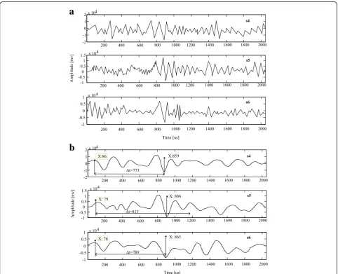
Based on the propagation velocity of the stress wave in the free length, it can be calculated that the theoretical value is 744 us when the stress wave arrives at the inter-face. Therefore, it is expected to find the feature point that is easy to distinguish around the theoretical propagation time. Several wavelet analyses were conducted on the sig-nals of s4, s5, and s6; it was found that under 5 scale low-frequency decomposition, the position of the max-imum wave trough can be acquired, as shown in Fig.7.
In Fig.7, it can be acquired that the propagation time of the elastic stress wave in samples 4#, 5#, and 6# was
almost equal. Based on the relationship between the wave velocity and time, the calculated rock bolt free length can be acquired. The relative difference is less than 5%. Specific parameters are shown in Table3.
3.3 High-frequency waveform analysis of signals ofs4,s5, ands6
The standard value of the wave velocity in the grouted part should be acquired. The signal ofs4should be
ana-lyzed. Through massive attempts, it was found that using high-pass filters with 5 scale can get the character point of the end of anchorage shown in Fig.8.
In Fig.8, based on the character point time difference between the start and the end of anchorage, the velocity of the elastic stress wave in the grouted part can be ac-quired, which was 1885 m/s.
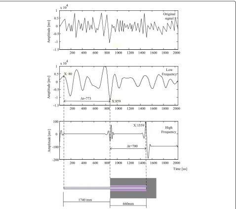
Fig. 10High-frequency waveform of sample 6# (unit: mm)
Table 4Non-destructive detect recognition parameters of sample 5#
Character point number Character point 1 Character point 2 Character point3 Character point 4
Propagation time (us) 892 1101 1180 1500
Time difference (us) 209 79 320
Wave velocity (m/s) 1885 4356 1885
Length (mm) 196 172 301
Actual length (mm) 200 160 300
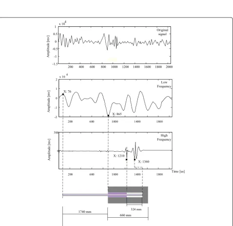
Through analyzing s5, the defect length and position of sample 5# can be acquired. First, the low-frequency analysis was used to acquire the character point of start of anchorage which was regarded as character point 1. In Fig. 9, it can be acquired that after reflection and transmission occurred in the interface between free part and anchorage part, the transmitted wave would propa-gate along the bolt rod until it reached the first imped-ance mismatch. Due to the fact that the wave propagated from the medium with large impedance to the medium with small impedance, the reflected wave sign did not change. It means that the first wave peak was regarded as character point 2. When the transmis-sion wave propagated from the empty area to the grouted section, the transmission wave had the third transmission and reflection. At this time, the reflected wave propagated from the medium with small imped-ance to the medium with large impedimped-ance. Conse-quently, the reflected wave changed from the peak to the trough. Therefore, character point 3 between the empty section and the compacted section can be found, which was the first wave trough. Last, at the end of an-chorage, the wave had the fourth transmission and re-flection. Due to the fact that the impedance of grout was higher than the air, the wave still propagated from the medium with large impedance to the medium with small impedance. Therefore, the wave peak was regarded as character point 4.
It was summarized that four character points can be acquired through wavelet transform analysis. Specific de-fect length, dede-fect position, and time recognition are tab-ulated in Table4.
Figure10shows the analysis results of signals6after it was decomposed with high-pass filters of 5 scale. The interface between the free part and the anchorage part was regarded as character point 1. After it, the first wave peak in the wave pattern was the start of the defect, and this point was regarded as character point 2. After the interface, the transmission waves still propagated. When it reached the end of anchorage, the wave propagated from the medium with small impedance to the medium with large impedance. The sign of reflection wave mu-tated, with the wave peak changing to wave trough. Therefore, in the waveform, it was reflected as the
maximum value of the first wave trough. And it was regarded as character point 3.
It was summarized that through wavelet analysis, three character points can be acquired. Specific defect length, defect position, and time recognition parameters are tab-ulated in Table5.
4 Conclusions
Based on the feature on sign transition of the elastic stress wave propagation in the impedance mismatch, the free length, the grouted length, the defect length, and the defect position of hollow grouted rock bolt can be acquired by the hammer impact method in the start of grouted hollow rock bolt. Attempts should be conducted on the scale of the wavelet transform to decompose the original signals collected by the signal collector to find the optimal character points. Experiment results certify that low-pass filters of 5 scale in wavelet transform can be used to easily distinguish the interface between the free part and grouted part. High-pass filters with 5 scale can be used to identify the defect character point pos-ition and the end of anchorage part. The research results can provide an experimental basement for further devel-oping non-destructive detecting technology and methods for hollow grouted rock bolts.
Acknowledgements
The authors thank the editor and anonymous reviewers for their helpful comments and valuable suggestions.
Funding
This research was supported by the Fundamental Research Funds for the Central Universities (2018BSCXB23) and the Postgraduate Research and Practice Innovation Program of Jiangsu Province (KYCX18_1971).
Availability of data and materials Please contact the author for data requests.
Author’s contributions
YH and YW designed the research. JT, PL, YT, and GH performed the research. YH wrote the paper. All authors read and approved the final manuscript
Competing interests
The authors declare that they have no competing interests.
Publisher’s Note
Springer Nature remains neutral with regard to jurisdictional claims in published maps and institutional affiliations.
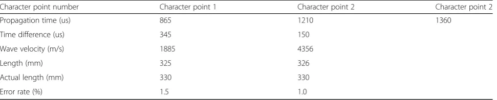
Character point number Character point 1 Character point 2 Character point 2
Propagation time (us) 865 1210 1360
Time difference (us) 345 150
Wave velocity (m/s) 1885 4356
Length (mm) 325 326
Actual length (mm) 330 330
Received: 9 October 2018 Accepted: 27 November 2018
References
1. B. Shen, Coal mine roadway stability in soft rock: a case study. Rock Mechanics & Rock Engineering.47(6), 2225–2238 (2014).
2. C. Wang, The optimal support intensity for coal mine roadway tunnels in soft rocks. International Journal of Rock Mechanics & Mining Sciences.37(7), 1155–1160 (2000).
3. S.Q. Yang, M. Chen, H.W. Jing, et al., A case study on large deformation failure mechanism of deep soft rock roadway in Xin’an coal mine, China[J]. Eng. Geol.217, 89-101 (2017).
4. X. Yang, J. Pang, D. Liu, et al., Deformation mechanism of roadways in deep soft rock at Hegang Xing’an Coal Mine. Int. J. Min. Sci. Technol.23(2), 307– 312 (2013).
5. J.M. Gere, B.J. Goodno,Mechanics of materials: Van Nostrand Reinhold Co
(1972).
6. Y. Cai, T. Esaki, Y. Jiang, An analytical model to predict axial load in grouted rock bolt for soft rock tunnelling. Tunnelling & Underground Space Technology.19(6), 607–618 (2004).
7. Y. Cai, T. Esaki, Y. Jiang, A rock bolt and rock mass interaction model. Int. J. Rock Mech. Min. Sci.41(7), 1055–1067 (2004).
8. D. Ma, X. Cai, Q. Li, H.Y. Duan. In-situ and numerical investigation of groundwater inrush hazard from grouted karst collapse pillar in longwall mining. Water.10(9), 1187 (2018).Y. Cai, T. Esaki, Y. Jiang, An analytical model to predict axial load in grouted rock bolt for soft rock tunnelling. Tunn. Undergr. Space Technol.19(6), 607–618 (2004).
9. C. Cao, T. Ren, Y. Zhang, L. Zhang, F. Wang, Experimental investigation of the effect of grout with additive in improving ground support. Int. J. Rock Mech. Min. Sci.85, 52–59 (2016).
10. D.H.S. Zou, J. Cheng, R. Yue, X. Sun, Grout quality and its impact on guided ultrasonic waves in grouted rock bolts. J. Appl. Geophys.72(2), 102–106 (2010).
11. J.Q. Fan, H.X. Dong, Y.H. Gao, M.L. Lou, Experimental study of shear stress distribution in internal anchoring section of a full-length grouting anchor. Journal of Experimental Mechanics.29(2), 250–256 (2014).
12. L. He, X.M. An, Z.Y. Zhao, Fully grouted rock bolts: an analytical
investigation. Rock Mechanics & Rock Engineering.48(3), 1181–1196 (2015). 13. E. Villaescusa, R. Varden, R. Hassell, Quantifying the performance of resin
anchored rock bolts in the Australian underground hard rock mining industry. Int. J. Rock Mech. Min. Sci.45(1), 94–102 (2008).
14. X.X. Miao, M.G. Qian, Research on green mining of coal resources in China: current status and future prospects. Journal of Mining & Safety Engineering.
26(1), 1–14 (2009).
15. H.F. Thurner,Boltometer-instrument for non-destructive testing of grouted rock bolts(1988).
16. Beard MD. Guided wave inspection of embedded cylindrical structures. Imperial College London.2002.
17. M.D. Beard, M.J.S. Lowe, P. Cawley, Ultrasonic guided waves for inspection of grouted tendons and bolts. J. Mater. Civ. Eng.15(3), 212–218 (2003). 18. V. Madenga, D.H. Zou, C. Zhang, Effects of curing time and frequency on
ultrasonic wave velocity in grouted rock bolts. J. Appl. Geophys.59(1), 79– 87 (2006).
19. C.S. Zhang, D.H. Zou, V. Madenga, Numerical simulation of wave propagation in grouted rock bolts and the effects of mesh density and wave frequency. International Journal of Rock Mechanics & Mining Sciences.
43(4), 634–639 (2006).
20. D.H. Zou, Y. Cui, V. Madenga, C. Zhang, Effects of frequency and grouted length on the behavior of guided ultrasonic waves in rock bolts. International Journal of Rock Mechanics & Mining Sciences.44(6), 813–819 (2007). 21. W.S. Li, G.Q. Gan, R.G. Zhu, T.Y. Wang, Research on application of
non-destructive detection technique to quality of grouting for engineering anchor bars. Rock & Soil Mechanics (2003).
22. J.Q. Zhang, W.U. Ji-Min, G. Peng, L.U. Er-Nan, M. Chen, Factors in quality of special bolts based on sonic non-destructive detection. Journal of Hohai University.37(2), 179–184 (2009).
23. G.W. Zhu, S.P. Peng, H.X. Wang, Test research on grouted density inspection of bolts using high frequency stress wave. Rock & Soil Mechanics.23(6), 787–791 (2002).
24. B. Sun, X.T. Zheng, C. Ceng, Z.F. Chen, S.S. Guo, Multi-scale analysis on anchoring defects diagnosis under multiple measuring points. J. China Coal Soc.39(7), 1385–1390 (2014).
25. H.E. Wen, K. Zhao, J.G. Ning, Properties of torsional guided wave propagating in grouting bolts. Chinese J. Comput. Mech.32(05), 650-655 (2015).
26. B. Zima, M. Rucka, Non-destructive inspection of ground anchors using guided wave propagation. International Journal of Rock Mechanics & Mining Sciences.94, 90–102 (2017).
27. Achenbach, J.Wave propagation in elastic solids. North-Holland Series in Applied Mathematics and Mechanics, vol. 16. North-Holland, Amsterdam (1973)
28. Liu G, Chen L. Development of a new type of green switch air entraining agent for wet-mix shotcrete and its engineering application[J]. Adv. Mater. Sci. Eng.2016, 2016.
29. R. Campbell, R.J. Mould, Impacts of gloving and un-mixed resin in fully encapsulated roof bolts on geotechnical design assumptions and strata control in coal mines. Int. J. Coal Geol.64(1–2), 116–125 (2005). 30. D-c. Xue, Y. Wu, K. Zhang, Experimental study and application on