Generation of infrared surface plasmon resonances with
high refractive index sensitivity utilizing tilted fiber
Bragg gratings
Tom Allsop,1 Ron Neal,2 Saeed Rehman,3 David J. Webb,1 Des Mapps,2,* and Ian Bennion1
1Photonics Research Group, Aston University, Aston Triangle, Birmingham, B4 7ET, United Kingdom
2School of Computing, Communications and Electronics, Faculty of Technology, University of Plymouth, Plymouth
PL4 8AA, United Kingdom
3FiberLogix Ltd, Ashley House, Vale Industrial Park, Tolpits Lane, Watford, Herts WD18 9QP, United Kingdom
*Corresponding author: [email protected]
Received 14 February 2007; revised 30 May 2007; accepted 31 May 2007; posted 4 June 2007 (Doc. ID 80156); published 23 July 2007
We demonstrate the use of tilted fiber gratings to assist the generation of localized infrared surface plasmons with short propagation lengths and a sensitivity of d兾dn⫽3365 nm in the aqueous index regime. It was also found that the resonances could be spectrally tuned over 1000 nm at the same spatial region with high coupling efficiency (in excess of 25 dB) by altering the polarization of the light illumi-nating the device. © 2007 Optical Society of America
OCIS codes: 060.2370, 060.2310.
1. Introduction
Gratings in fibers—including long period gratings (LPGs), fiber Bragg gratings (FBGs) and tilted fiber Bragg gratings (TFBGs)—and surface plasmon reso-nance (in both planar and fiber configurations) may all be used to detect changes in the refractive index of various substances with potential applications in chemistry, biochemistry and biology [1– 4]. Surface plasmon resonance (SPR) is a prominent optical phenomenon that involves a resonant transfer of the pumping light energy to a surface-plasmon (SP) mode in the form of collective oscillations of elec-trons in the metal [5]. It is well known that SP generation is very sensitive to the polarization of the illuminating light, its wavelength and its angle of incidence on the metal surface which is used to detect index changes in biochemical兾chemical reac-tions [6]. SPR biosensors offer the opportunity for real-time and label-free monitoring of biomolecular interactions [7]. The majority of SPR based systems operate in the visible or near infrared part of the
spectrum which gives a probe depth (the spatial extension of the SP into the surrounding environ-ment from the surface of the metal) of around 200 nm to 300 nm [6]. The SPs exist at a metal– dielectric interface and obey the following dispersion relation for two homogeneous semi-infinite media:
 ⫽k
冑
冉
m·ns2
m⫹ns2
冊
⫽kn2sin共兲, (1)
wherekis the free space wave number,mis the per-mittivity of the metal 共m ⫽ mr ⫹ imi兲, ns is the refractive index of the sample to be tested,n2is the
refractive index of the cladding andis the incident angle of the light onto the metal兾dielectric interface which determines the wave-number projection onto that interface.
Generally fiber gratings comprise an axially peri-odic refractive index variation inscribed in the core of a photosensitive single-mode optical fiber by ultra-violet radiation, or other means, which couples light from the core to other core modes (FBG), to cladding modes (LPGs) or to some combination of core, clad-ding and radiation modes (TFBGs) at discrete wave-0003-6935/07/220001-05$15.00/0
lengths [8]. There is a considerable body of published research relating to fiber grating based devices; with the majority of the these devices, the highest index sensitivity is obtained with test sample indices over
⬃1.4 [9] and they generally have less sensitivity in the aqueous index regime. Whilst the majority of work done with SPRs in a fiber configuration has been done in the visible-NIR wavelength range of 600 nm to 800 nm, going to longer wavelengths may improve sensor performance [5] and reduce costs by making use of standard telecommunications compo-nents.
We report on a novel SPR fiber device utilizing a TFBG to enhance the coupling of the illuminating light to a SP generated on a silver coating applied to a lapped single mode fiber. It was also observed that the spectral location of maximum coupling to the SP was dependent upon the polarization state of the illuminating light and could be tuned from 1100 nm to 1700 nm. Calculations performed on measure-ments from the experimental data suggest that the propagation length of these infrared SPs is short
共⬃100 nm兲compared to the spatial extension (probe depth) from the silver兾medium interface, which is around 1.5m. It was found that for a device that is still to be fully optimized, the maximum spectral in-dex sensitivity 共d兾dn兲 was 3365 nm for the index range 1.335 to 1.370 (suitable for refractive index monitoring of aqueous solutions) for SPs generated from 1200 nm to 1700 nm. Our results suggest that with an optimized fiber device, at least another order of magnitude increase in the sensitivity may be pos-sible.
2. Fabrication and Characterization
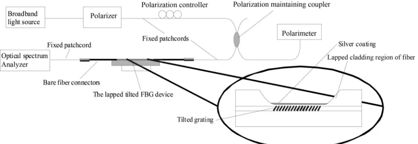
The SPR fiber devices are constructed in three stages [10]. Firstly, the TFBG is written in a UV photosen-sitive single mode fiber using a uniform phase mask mounted on a goniometer and then tilted to a specific angle; labels are added to indicate the orientation of the tilted grating. Secondly, the fiber is lapped down to 10m from the core-cladding interface. The labels on the fiber are used to indicate which region of clad-ding is to be removed so that the grating vector, the
fiber axis and the normal to the lapped surface all lie in a plane (see Fig. 1). Thirdly, the flat of the lapped fiber is then coated with silver (thickness 35 nm) us-ing a sputter machine and mask.
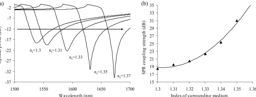
The fiber devices are characterized with a broad-band light source, the light being passed through a polarizer, a polarization controller and a polarization maintaining coupler before illumination of the sam-ple, with the transmission spectra being monitored using an optical spectrum analyser (OSA) with a res-olution of 0.005 nm, and the polarization of the illu-minating light via a second output arm of the coupler, see Figure 1. Initially a series of these devices was fabricated with angles of tilt from 1° to 9° degrees. It was found that it was possible to generate SPRs with all of them. For a single fiber device it was possible to produce SPRs over a large spectral range from 1200 nm to 1700 nm, whilst the device was sub-merged in test sample fluids, see Fig. 2 (note that the features seen at maximum coupling of the SPR are artefacts due to the normalization procedure of the OSA and that the maximum coupling bandwidth can be considerably narrower. The polarization depen-dency of these SPR devices was investigated us-ing the schematic shown in Fig. 1. The devices were submerged into various index matching solutions and the polarization of the illuminating light was changed. It was found that the maximum extinction induced by the SPR coupling is very much dependent upon the polarization of the illuminating light. It is expected that the coupling efficiency and spectral lo-cation of the SPR should dramatically change with polarization, with some polarization states resulting in low coupling efficiencies of only a few dB [11]. However, whilst variations of the coupling strength of the SPRs were observed with changes in polarization, our devices still produced large extinction ratios over the wavelength range studied, see Fig. 2. In Fig. 2 it can be seen that over the observed spectral range (1220 nm to 1700 nm), the device with a 7° degree tilt angle exhibited extinction ratios in excess of 35 dB in a solution with a refractive index of 1.360. It can also be seen that the maximum extinction ratio occurs with a surrounding medium with a refractive index of
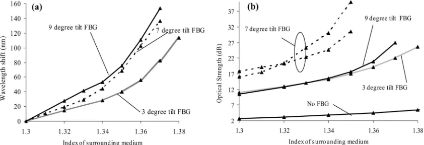
around 1.36 with some reduction for both lower and higher refractive indices. It can also be seen from Fig. 2 that the extinction range of these devices ranges from around 1 dB to 35 dB for a given wavelength, as a function of polarization. It was also found that changing the tilt angle of the fiber Bragg grating changed the maximum extinction ratio achievable when altering the polarization of the illuminating light, see Fig. 3.
Comparing the coupling strength of the SPR with and without a grating (Fig. 3), it can be seen that the grating greatly enhances the SPR coupling in the aqueous index regime from⬃4 dB without grating to 25 dB for the 7 degree tilted grating with coupling increasing with increasing surrounding index to in excess of 35 dB. It was also observed that spectral features in the fiber device with no grating were very much broader than with the gratings present. These spectral sensitivities obtained in the aqueous index regime are comparable to the highest sensitivities obtained with SPR based devices [3]; see Fig. 3(a). The highest spectral sensitivity obtained was d兾dn
⫽3365 nm from the 9 degree tilt angle device leading to a resolution (under the assumption of a 0.1 nm measurement resolution for the resonance
wave-length) of⬃2 ⫻10⫺5over the index range of 1.34 to
1.38. For the fiber devices investigated to date, the spectral sensitivities varied from 700 nm to 1400 nm over the index region of 1.3 to 1.34 and from 2100 nm to 3400 nm over 1.34 to 1.38. The power variation yielded results of 106 dB to 300 dB over the index region of 1.3 to 1.34 and 250 dB to 730 dB over 1.34 to 1.38. The 7 degree tilted grating sensor achieves the strongest coupling to the SPR, with strengths varying from 10 dB to⫹30 dB in the aqueous index regime. Using an atomic force microscope (AFM) it was found that the silver coating had an average thickness of 35 nm with a standard deviation of
⬃6 nm. Using this information along with the disper-sion relationship for silver [12] and the cladding dis-persion relationship of the D-shaped fiber, it was possible to reproduce similar transmission spectra to those of the SPR device forp-polarized light, by im-plementing Fresnel’s equations for a three layered system for different refractive indices of the sur-rounding medium. The reflectivityRof the fiber coat-ing at various wavelengths forp-polarized light, with
E0pthe incoming andErpthe reflected field is given by expression 2 (see Ref. 6).
Fig. 2. The transmission spectra of fiber SPR devices illuminated with light of various polarization states. (a) Device in a solution with an index of 1.360 (Ag thickness 35 nm, angle 7°, length 2.8 cm). (b) Device in a solution with an index of 1.380 (Ag thickness 35 nm, angle 3°, length 5.0 cm).
R⫽
冏
Erp
E0p
冏
2⫽
冏
rn2nmp⫹r nmns
p· exp
共2iKz,nmd兲
1⫹rn2nm
p·r nmns
p· exp
共2iKz,nmd兲
冏
2
(2)
where d is the thickness of the metal coating, and
ri,jP⫽
冉
Kz,i
i ⫺
Kz,j
j
冊冒冉
Kz,i
i ⫹
Kz,j
j
冊
is thep-polarization
amplitude reflection coefficients between layersiand
jwhere theKs are the wave vectors of the illuminat-ing incident light normal to each layer, andjare the permittivities of thejth layer,nmis the metal index,
nsis the index of the surrounding medium andn2is
the index of the fiber cladding; for detail see [6]. In-specting the results of the simulation plotted in Fig. 4 shows the bandwidths for indices of 1.35 and above to be considerably narrower than the experimental results shown in Fig. 2(a); ⬃100 nm compared to
⬃400 nm. The width of the observed resonances sug-gests that these SPs have short propagation lengths, which may be exploited for some applications (SPR imaging techniques). To this end the propagation constants of the SP along the metal兾dielectric inter-face were also calculated from the experimental data, thus giving some indication of the spatial localization of the SPs. The intrinsic loss 共⌫i兲 of the fiber SPR device is based upon the optical properties of the materials used, and can be approximated using [13]
⌫i⫽
ns3k0i 2r2
, (3)
wherensis the refractive index of the test sample,k0
is the free space propagation constant,i andr are the imaginary and real permittivities of the metal film. The radiative loss term (⌫rwhich can be inter-preted as an additional loss generated from light be-ing reradiated into the claddbe-ing caused by surface roughness) can used to obtain the propagation con-stant of the SP. This loss term was estimated from experimental results such as those shown in Figure 1. Using the expression given by [13],
Wk⫽2共⌫i⫹ ⌫r兲兾共n2k0cos共兲兲, (4)
whereWkis the width of the SPR at half maximum andn2is the index of the cladding and whereis the
angle of incidence on the metal coating of radiation emitted from the TFBG. The angle is calculated using the scattering angles associated with the vari-ous TM propagation constants 共n兲 generated by a D-shaped fiber with a silver coating, by the relation-ship given by the ray approach; sin共兲⫽n兾n2.can
be used to determine the projection of the incident wave-number along the metal兾dielectric interface. Surface plasmons are generated when this wave-number projection matches the dispersion relation of the plasmons given by expression 1. The TFBG en-hances coupling to higher order TMv modes to pro-duce a larger range of scattering angles than in multimode or circular cladding single mode fiber [14]. These propagation constants and their associated coupling coefficients are calculated using a dispersion relationship derived in [15]. It was found that only a small number of modes contributed significantly to the SP generation (work to be published).
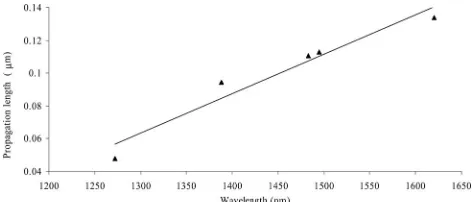
The radiative loss term 共⌫r兲 is a quantity that is used to obtain the propagation length; Lx (which yields an estimate of spatial resolution) of the SP via the characteristic propagation constant [6] which is defined for a non-smooth surface as:
Lx⫽1
冒
2冉
Im冉
k0冑
m·ns2
m⫹ns2
冊
⫹ ⌫r
冊
. (5)work is clearly required to fully explain this behav-iour. These propagation lengths are of similar dimen-sions to the granularity of the silver surface observed by AFM, which suggests that these devices are pro-ducing highly spatially localized surface plasmons. Furthermore, calculations to reproduce the transmis-sion spectra of the SPR devices suggest that for dif-ferent polarization states, SPs are being generated at the same spatial location of the SPR fiber device but with different resonant wavelengths (work to be pub-lished). This suggests that the spatial extension of the SP evanescent fields (E-field component normal to the metal兾dielectric interface) can be controlled at the same spatial location on the SPR fiber device by controlling the polarization of the illuminating light.
3. Conclusion
We have demonstrated a novel SPR fiber device uti-lizing a tilted fiber Bragg grating to enhance the cou-pling of the illuminating IR light to spatially localized surface plasmon resonances on a silver coated lapped single mode fiber. It was found that by altering the polarization of the light the resonance could be tuned over the spectral range from 1100 nm to 1700 nm with extinction ratios in excess of 35 dB for the aque-ous index regime (1.34 to 1.37). Also the polarization dependence can control the spatial extension of the SPR from the metal兾dielectric interface at a given location.
References
1. S. A. Vasiliev and O. I. Medvedkov, “Long-period refractive index fiber gratings: properties, applications, and fabrication techniques,” Proc. SPIE4083,212–223 (2000).
2. K. Schroeder, W. Ecke, R. Mueller, R. Willsch, and A. Andreev, “A fiber Bragg grating refractometer,” Meas. Sci. Technol.12,
757–764 (2001).
3. M. Piliarik, J. Homola, Z. Mankova, and J. Ctyroky, “Sur-face plasmon resonance sensor based on a single-mode polarization-maintaining optical fiber,” Sens. Actuators B
90,236 –242 (2003).
4. J. Homola, “Surface plasmon resonance sensors: review,” Sens. Actuators B54,3–15 (1999).
5. S. Patskovsky, A. Kabsahin, M. Meunier, and J. Luong, “Prop-erties and sensing characteristics of surface plasmon reso-nance in infrared light,” J. Opt. Soc. Am. A20,1644 –1650 (2003).
6. H. Raether,Surface Plasmons on Smooth and Rough Surfaces and on Gratings(Academic, New York, 1997).
7. J. M. Brockman, B. Nelson, and R. Corn, “Surface plasmon resonance imaging measurement of ultra-thin organic films,” Annu. Rev. Phys. Chem.51,41– 63 (2000).
8. T. Erdogan, “Fiber grating spectra,” J. Lightwave Technol.15,
1277–1292 (1997).
9. M. Iga, A. Seki, and K. Watanabe, “Gold thickness dependence of SPR-based hetero-core structured optical fiber sensor,” Sens. Actuators B106,363–368 (2005).
10. T. Allsop, R. Neal, S. Rehman, C. Zhang, D. Webb, D. Mapps, and I. Bennion, “Surface plasmon resonance generation utiliz-ing gratutiliz-ings for biochemical sensutiliz-ing,” in Proceedings of the Eighteenth International Conference on Optical Fiber Sensors (Optical Society of America, Washington, D.C., 2006), paper WA4.
11. J. Homola and S. Yee, “Novel polarization control scheme for spectral surface plasmon resonance sensors,” Sens. Actuators B51,331–359 (1998).
12. E. D. Palik and G. Ghosh, Handbook of Optical Constants (Academic, San Diego, 1998).
13. E. M. Yeatman, “Resolution and sensitivity in surface plasmon microscopy and sensing,” Biosens. Bioelectron.11, 635– 649 (1996).
14. R. C. Jorgenson and S. Yee, “A fiber-optic chemical sensor based on surface plasmon resonance,” Sens. Actuators B12,
213–220 (1993).
15. C. Tsao,Optical Fiber Waveguide Analysis(Oxford, New York, 1992).