5 | P a g e
PV SINGLE PHASE GRID CONNECTED CONVERTER USING FUZZY PID
CONTROLLER
JAYAPRAKASAN P
M.Tech Scholer, Division of Electrical & Electronics Engg School of Engineering, Cochin University of Science & Technology Cochin,Kerala India
PRATHAP KUMAR S
Scientist Engineer E, National Institute of Electronics & Information Technology Kozhikode. Kerala,India
DR C A BABU
Professor, Division of Electrical & Electronics Engg School of Engineering, Cochin University of Science & Technology, Cochin, Kerala India
ABSTRACT:
This paper proposes the Single phase multy stage grid interfaced Photo Voltaic System. The primary stage is DC-DC Booster stage which is governed by a MPPT system. Output voltage of Booster stage is controlled by Incremental conductance algorithm .Depending upon the solar Irradiation and temperature the output voltage of PV panel is varied. By MPPT the maximum power is drawn from the PV system and fed to Inverter stage. This stage controls the power flow to the grid. The proposed control will reduce the voltage ripple in DC link voltage. The conversion efficiency of Inverter will decrease due to ripples in DC link voltage ,because it it will cause an excessive stress on the IGBTs or MOSFETs. This also results harmonics in the grid current. This paper describes an efficient and reliable control technique , Fuzzy Proportional Integral Differential (FPID) for stabilizing the DC- link voltage. PV Array output is varied with variations in solar irradiation, temperature and shadow that means Photo Voltaic system is nonlinear. The change of plant parameters will not affect the proposed control technique. In this proposed scheme, power flow and THD levels are analyzed at different DC-link voltage. This study describes that this control technique have a capability to maintain a same grid current THD at transient and steady state conditions. Comparing to conventional PID control the % THD is small. Minimum settling time and fast DC-link voltage stabilization are also shown in this paper by this control technique. Finally the proposed system offers an excellent dynamic performance for reducing the DC-link voltage ripples and stabilization that is verified in MATLAB simulink tool
KEYWORDS: Fuzzy Propotional Integral Control; Maximum power point tracking
I. INTRODUCTION:
6 | P a g e
consists of dc-ac converter which supplies the extracted power from the PV array to ac grid. Nevertheless, there are many factors which affect the efficiency of PV panels such as air temperature, solar radiation and shadowing. In the day time these parameters constantly change. Accordingly, PV panel output power is changed by parameters. Different methods and techniques are used to eliminate this situation. The Maximum Power Point Tracking is one of the methods. The MPPT will sense the PV voltage and current and according to those values it will generate gate pulses for Boost chopper. For grid connected converters, efficient dc link voltage control is very important to reduce the voltage fluctuations in the dc-link. The DC-AC converter stage will supply ac power to the grid. For controlling the output voltage the gate pulses for the converter is generated by using conventional PID controller. But for nonlinear system, Fuzzy PID control is more effective. When FPID control is used the percentage THD will be comparatively reduced.
Power generated by PV system is effectively fed to grid by stabilizing the DC link voltage. The dc link voltage (1) stabilization is proposed without sensing the dc link voltage but by sensing PV voltage and current. Here the duty cycle of Boost chopper is controlled according to MPPT algorithm. The losses in converter stage is compensated by ANN in this paper. The DC-AC converter stage is controlled by PR controller. The V I characteristics of PV cell is nonlinear .It depends on the solar insulation and temperature. So the system needs efficient Maximum Power Point Tracking. Ripple Correlation Control (RCC) (2) yields fast and parameter insensitive is suitable for single phase single stage PV system. In Distributed Generations there are AC and DC sources and it forms DC sub grid and AC sub grid. The interface between these two (3) is Dual –Active-Bridge (DAB ) and inverter Here DAB maintain the DC link voltage and inverter controls the power output by using feed forward loop which can improve system performance. The Predictive voltage control based on Energy- Balance (4) is applied for DC link voltage stabilization and it reduces output ripple. The DC-link voltage is not simply the sum of constant value and second order ripple. The inductance of the AC filter influences the amplitude of the DC-link voltage ripple. In this paper, reactive power is assumed to be zero that is grid current is in phase with voltage. When DAB converter (5) is used as first stage of dual stage PV grid inter phase system, the phase angle between the two voltages will decide the power that is transferred to grid. This angle is determined by sensing PV voltage DC-link voltage. The LCL filter at the input of (6) boost converter will reduce the inductance of Boost converter , which will reduce the cost
of converter. The author in (7) shows that the fuzzy PI MPPT is more effective and accurate than the Constant Voltage Controlled MPPT. In a 3 phase grid connected PV system the 3 phase VSC can also act as Active Power Filter in addition to stabilizing the DC-link voltage (8) without any additional hardware. MPPT using Fuzzy logic controller is simple and robust (9).This method can handle nonlinearity and it does not require the knowledge of exact model. The PV system is non linear. Conventional PID (10) controllers are not suitable for non linear system. In (4) Proportional Integral based Maximum Power Point, tracking control algorithm is proposed. This control enhances the generated power from PV system. The proposed system offers a PV V&I sensed Incremental conductance + Integral MPPT that controls the duty ratio of Boost chopper. An effective Fuzzy PID control is used in inverter stage to stabilize the DC-Link voltage.
II. PV MODULE:
PV Cell is a PN junction which converts solar irradiation directly to Electricity. Fig(2) shows the equivalent circuit. The PV cell current is Iph and series and shunt resistances are Rsh and Rs respectively. Normally the series resistance is small hence for simplifying the analysis it may neglect. But the value of shunt resistance is large. When PV cells are connected in series resulting arrangement is called PV module. For getting large voltage these modules are connected in series or parellol.The resultant arrangement is called PV array. PV arrays are used in Solar power stations..
Fig.1, Equivalent Circuit of PV Cell
7 | P a g e
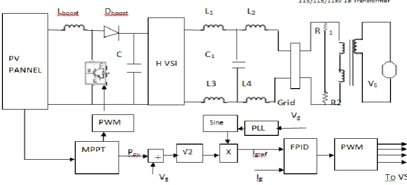
Fig.3. PV Grid Connected System
III POWER SYSTEM MODEL:
Figure 4.1 shows the proposed PV Grid connected system. This is a two stage PV system. First stage is a DC to DC Boost chopper stage. The function of DC-DC converter is to execute the MPPT algorithm by controlling its input terminal voltage by sensing the PV voltage and PV current. The MPPT algorithm used in this proposed system is Incremental conductance + integral regulator. This MPPT algorithm is simple and it automatically control the duty
cycle. This sense the PV voltage and PV current and generate the gate pulses for the Boost chopper. For
transferring maximum power to the grid it is required to stabilize the voltage. The un stabilized DC link voltage will cause large harmonic distortion in grid current and low power transfer from PV system to grid. The higher voltage at DC-link will cause stress in the power semiconductor switches used in Inverter stage. In the proposed system the DC link voltage is stabilized by a fuzzy PID controller in load current control loop. The second stage is inverter stage. This stage convert the DC voltage to AC voltage that is fed to the grid. The out put current of the H Bridge inverter contains the ripple. To reduce the ripple and thus to minimize the THD within IEEE standard LCL filter is used in out put circuit. In addition to this filter, since the PV system is a non linear, FPID, fuzzy Proportional Integral Derivative Controller is used in outer current control loop. This reduces the oscillation in DC-link voltage at transient and steady state conditions. It also helps to reduce the THD to considerable limit and reduces the settling time comparing to conventional PID and PR controller.
A. BOOSTER STAGE
Boost chopper is basically DC –DC converter its output voltage
Vo = Vs/ (1-D), here D is duty ratio.
The gain of boost chopper is Gboost = Vout
Vin = Vdc Vpv
That is = (1−D)1
MaximumSwitching Current ∆I = D×Vpv
Fsw×Lboost
If L is not known
then ∆I = (0.2 to 0.4) Iout(max) Vout Vin
So L = Vin×(Vout−Vin)
∆I×Fs×Vout
Duty cycle D = 1 − Vin
Vout
Output capacitor Cout = Iout(max)×D Fsw×∆Vout
Vout = Iout(maxx)
(1−D) +
∆Il 2.
B .INVERTER STAGE:
This stage convert the input Dc voltage to AC voltage at desired frequency and fed to the grid. For filtering the the switching frequency harmonics present in the output current LCL filters are used.
Fig 4. Voltage and Current wave form The voltage across the inductor is given by: V= L di
8 | P a g e
For H Bridge inverter V = Vbus -Vo
So Vbus - Vo = L di
dt = Li × ∆Ipp D×Ts
∆Ipp = (Vbus − Vo)×D×Ts
Li
Assume modulation index be ma the Duty cycle is given as
D = ma sine(ωt)
Vo = VDC D
Therefore,
∆Ipp =Vbus×Ts×ma×sine(ωt)×(1−sine(ωt))Li
Differentiating the above equation and equating to zero we get,
sine(ωt) = 1 2ma
∆Ippmax =Vbus×Ts 4×Li
Li = Vbus
4×Fs×∆Ipp max
IV. SIMULATION RESULTS:
Figure shows the proposed model of grid connected PV system. Here shows a grid with voltage of 200V and a 11KV/115-115 transformer that is connected to the grid. A 2.5 Kw PV array is connected to the grid through a DC-DC Boost chopper and single phase H bridge voltage source inverter. Maximum power point tracking (MPPT)
implemented in the boost chopper by means of incremental conductance +Integral Regulator technique. PV array delivering a maximum of 2500 W at 1000 W/m2 sun irradiance. A 20Khz DC-DC boost converter
increasing voltage from PV natural voltage to maximum of 550V.switching frequency of H bridge inverter is 20KHz.The current control loop used Fuzzy PID controller because the PV system is non linear
A. FUZZY PID CONTROLLER
Proposed Fuzzy logic controller is help to achieve reasonable steady state error, settling time and reduced ripple in VSC output current. This is achieved because it does not sensitive to the plant parameter .The proposed system is used the Mamdani model and triangular membership functions. FPI have two inputs error and change of error (E & CE). It has one out put. In the proposed system reference current Iref is compared with
Igrid. Here reference current depends on PV Power and Grid
voltage. The figure 6 shows the fuzzy rule base for the proposed system.
9 | P a g e
Fig.6 Fuzzy Rule
Here
NS is Negative Small,
NL is Negative Large,
NM is Negative Medium,
NVL is Negative Very Large ,
Z is Zero,
PS is Positive Small,
PM is Positive Medium,
PL Positive Large and
PVL is Positive Very Large
Defuzzification method used in simulation is centroid method.The proposed system have two inputs . One is Error(E) and the other one is Change of Error (CE). E = e(k)
e (k) = Iref – Igrid
Iref = (Ppv )/VgridPpv Igrid
CE = e(k) – e(1-k)
Fig.7 Fuzzy Rule for Proposed Control
Fig.8 Rule Surface View
B. STEADY STATE ANALYSIS:
MATLAB simulink 2017 is used for the simulation of proposed system. Neo Solar Power 7E00-6A 250-B PV Array is used. The VI characteristics and Power Vs Voltage characteristics of array is shown in figure.9
Fig.9 Characteristics of Neo Solar Power
Steady state results of proposed system are shown in following figures. The figure 11 shows DC out put voltage of PV Array. PV voltage become study after some seconds this is due to the characteristics PV panel. PV modules are connected in string so open circuit voltage @ solar irradiation of 1000w/m2 is 380 V at 250 C. Dc link voltage
is varied from 300V onwards. But the results shows the maximum power is transferred at minimum THD ,that is bellow IEEE standards, is at 350V. In the proposed system DC link voltage fluctuations are minimized. This helps to reduce the stress on the VSI components.
10 | P a g e
Figure 10 shows the variation of % THD in grid current at different DC-Link voltage. Simulation results shows that % THD is comparatively small at 350 V DC-link voltage.
Fig 11. PV Output Voltage
Figure 12 shows the DC –Link voltage wave form at 1000W/m2irradiance and 250 C. Figure 13 shows the H
Bridge Voltage Source Inverter output voltage. The results shows that system takes about 5 seconds to reach the steady state value. This is due to the characteristics of the PV Array used in simulation that is sown in figure 9.
Fig.12. DC-Link Voltage
Steady state grid voltage and grid current wave forms are shown in figure 13. The voltage THD is very small and current THD is 0.028 at 1000 W/m2 irradiance. Figure 13
shows the comparison of Proposed system with uncompensated conventional PR control based system and loss compensated conventional PR system. Comparing to these two systems the proposed system introduce small THD in the grid current.
Fig 13. Grid Voltage and Current
Fig 14 % THD at different solar irradiance
C. TRANSIENT ANALYSIS:
For transient analysis the solar irradiance is varied at 2.5 seconds keeping temperature as 250 C. (Figure 15) .
Figure 16 shows the variation on PV Voltage. Figure 17 shows the transient result of DC-Link voltage. Here, in the proposed system the settling time is 0.1 seconds.
Fig.15 Solar Irradiance and Temperature
Fig 16 PV Voltage
Fig 17 DC- Link Voltage
Fig 18 Grid Voltage and Current
V. CONCLUSION:
11 | P a g e
the settling time reduced comparing to conventional systems. The proposed system is not account the converters loss. Converter loss will caused for reduced efficiency of the system. By introducing soft switched converters and loss compensation for filter inductance loss we can improve the overall efficiency of grid inter phase PV system.
REFERENCES:
1) N E Zakzouk, A K Abdul salam, A A Helal And B W Williams “PV Single Phase Grid Connected Converter: DC-Link Voltage Sensor Less Prospective”. IEEE Journal of Emerging and Selected Topics in Power Electronics.DOI 10.1109/JESTPE 2016
2) Ch. L. S Srinivas, Sreeraj E S “ Maximum Power Point Tracking Technique Based on Ripple Correlation Control for Single Phase Photo Voltaic system with fuzzy Logic Controller” Energy Procedia 90 (2016) 3) Yanjun ian , Zhe Chen, Xiaofen Sun and Anting Hu
“Coordinative Control of Active Power and DC Link voltage for Cascaded Dual- Active-Bridge and Inverter in Bidirectional Applications” IEEE Transactions on Power Electronics 13 November 2014.
4) Fanbo He , Zhengming Zhao, Liqiang Yuan Sihao Lu. “ A DC-Link Voltage Control Scheme for Single-Phase Grid Connected PV Inverters. “ IEEE Transactions published 2011.
5) Mostafa I Marei, Hadi EI Helw, and Mohamed Al-Hasheem “ A Grid- Connected PV Interface System Based On The DAB Converter”. IEEE Transactions on Power Electronics. 2015.
6) Pallavi Bharadwaj, Vinod Jhon Department Of Electrical Engineering, IISC Banglore “Direct Duty Ratio Controlled MPPT Algorithm for Boost Converter in Continuous and Discontinuous Modes of Operation,978-1-4799-6046-0/14/2014 IEEE
7) Pravesh Kumar, Rupendra Kumar Pachauri, Yogesh K Chuahan, Member IEEE “ Duty Ratio Control Schemes of DC –DC Boost Converter Integrated With Solar PV System 978-1-4673-7492-7/15 2015 IEEE
8) Sina Vahid, S Hamid Fathi, Hassan Rasteger And Gevork B Gharehpetian “ Improving The Performance of PV Grid Interface Inverter Using the Adaptive Hysterisis Band Current Controller” 978-1-4673-9280-8/15 2015 IEEE
9) Power Quality Improvement of Single Phase Grid Connected PV System with Fuzzy MPPT Contrl. 10)Prof K A Gopala Rao, B Amarendra Redy And P Durga