Secured Software Defined Radio using FPGA
Veena Gopan Ambily K
M. Tech Student M. Tech Student
Department of Electronics & Communication Engineering Department of Electronics & Communication Engineering Mar Athanasius College of Engineering, Kothamangalam Mar Athanasius College of Engineering, Kothamangalam
Mary Joseph
Associate Professor
Department of Electronics & Communication Engineering Mar Athanasius College of Engineering, Kothamangalam
Abstract
This paper contains the design and construction of an SDR. Software Defined Radio (SDR) is a radio communication system where components are implemented mainly in software instead of hardware. It ensures flexible, long life radio communication. The security of data is given by using an encryption scheme called Baker mapping and a secret key, which helps to identify the authenticity of the message. The encrypted message also adds as another layer of security. Here encryption, decryption, digital up conversion and down conversion are done in FPGA.
Keywords: FPGA, Encryption, Decryption, SDR
________________________________________________________________________________________________________
I. INTRODUCTION
A radio is any kind of device that wirelessly transmits or receives signals in the radio frequency part of the EM spectrum to facilitate the transfer of information. With the exponential growth in the ways and means by which people need communicate each other, it is very essential to modify these existing radio devices. So modifying radio devices easily and cost-effectively has become business critical. There lies the importance of SDR. Software defined radio (SDR) technology brings the flexibility and cost efficiency.
SDR is a radio communication system where components that are implemented in hardware are implemented by means of software on a PC or embedded system. It is flexible and upgradeable and serves as longer lifetime radio equipment. The SDR provides a versatile wireless communication solution for a wide range of applications.
Traditional radio communication systems needs a lot of hardware components which make the platform cost very high, high noise and less flexible. SDR receiver is able to decode all the signals so they are more flexible. The data that is transmitting must be secured throughout the transmission. For security of data an encryption mechanism is also provided. So our objective is to design of SDR transceiver in FPGA design and provide an encryption mechanism for the data transmission in the SDR.
Software Defined Radio proposed in the paper consists of transmitter and receiver and they are interfaced digitally. Two FPGA boards are used here, one will be working as a transmitter and the other one will act as receiver.
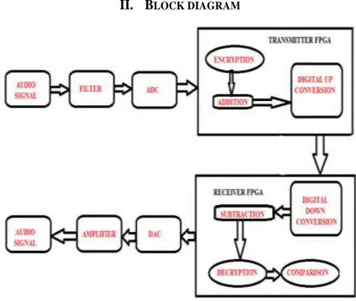
II. BLOCK DIAGRAM
For the transmitter it needs an audio input which is analog and must be converted to digital form for processing in FPGA, since FPGA works only in digital domain .The audio signal is taken from an MP3 player via a RCA jack. The digital input audio signal, is added with a message which is encrypted using an encryption technique called baker mapping. This added up signal is digitally up converted and transmitted.
At receiver end this signal is digitally down converted and taken out for further processing after decryption. The decrypted message is checked and verified for the authenticity of the transmitted signal. An indication for the security is given at the hardware section for this authenticity.
III. TRANSMITTER
The audio signal is taken from an MP3 player via an RCA jack and is connected to FPGA board. The audio signal is filtered out by using AD8606 filter IC. The filtered output is given to AD7476A.
Fig. 3: Transmitter side
In the transmitted side FPGA the digital audio signal is added with the encrypted authentication message. For encryption baker mapping can be used. This is done using a key, the same key is needed at the receiver end for decryption. So without the reverse algorithm and same key we can’t decrypt the authentication message.
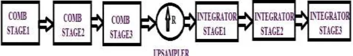
After the encryption, the signal will be digitally up converted at a rate of 16.This section consists of 3 comb filter stages followed by an upsampler followed by 3 integrator stages.
Fig. 4: Digital Up Conversion
The resultant interpolated signal will be transmitted to the receiver.
IV. ENCRYPTION AND DECRYPTION
For encryption baker mapping is used. The authentication message chosen here is a 1 bit 8 × 8 message and which can be extended as the power of 2, such as 8, 16, 32, 64 etc. The encryption is done by using a key. The same key is needed at the receiver end to decrypt the message. If another key is lost then the authentication is lost and for that the decrypted message is compared with the stored original authentication message. If both are same it or not is indicated by a led.
The key selection is done by the following criteria’s
The elements sum must be 8
1 is not taken as element
8/each element must be perfectly divisible
8 is taken since the message is 8 × 8 size which can be varied according to the message size. As the message size is increased the no of keys that can be used will also increase and this will increase the degree of security. As 8 is the size here up to 5 keys can be used for a 16 ×16 size the no of keys can be used increased 5 to 6 times.
The encrypted message is added to the LSB of the audio signal. And at the receiver from the LSB the message is extracted and decrypted using same key. And the decrypted message is compared with the original one.
Fig. 6: Decryption
Baker mapping is the processes of mapping a message to itself. The equation used for baker mapping is given below in equation one
X′ = N ni
∗
(
X − Ni)
+ Y mod(
Nni
)
Y’=
niN
∗ (Y − Y mod (
Nni
)) + N
iEquation(1)
Each element in the matrix will be shifted to another cell according to the key. And using the same key at the receiver end the elements will brought back to their original positions if same key is not used at the receiver end the elements will not fall on the same place and when we compare them with the original one they will not be same
V. RECEIVER
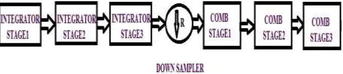
The received digital signal is down converted. The digital signals are down converted and subtracted. Digital down conversion is the reverse operation of digital up conversion. At the receiver side we are decreasing the sample rate. So Digital down conversion starts with three integrator stages followed by a down sampler followed by three comb stages.
Fig 7: Digital down Conversion
The audio signal is taken out and given for further processing. The remaining signal after subtraction is decrypted using the same key as used in the transmitter. It is compared with the original message stored and checked for authentication.
The digital signal is converted to analog using a DA121S101 DAC. Then the signal is amplified and fed to the speaker
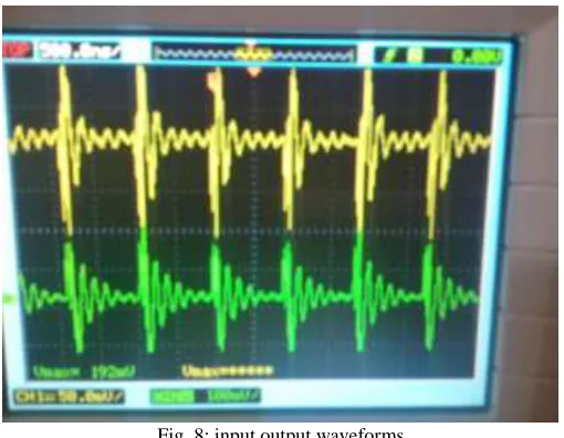
VI. RESULTS
Fig. 8: input output waveforms
The hardware setup is given in the fig 9 the left side board is used as the transmitter and the right side one is the receiver
Fig. 9: Hardware
The baker mapping is checked using matlab and implemented in verilog. The results we obtained when done it in matlab are in the below figures.
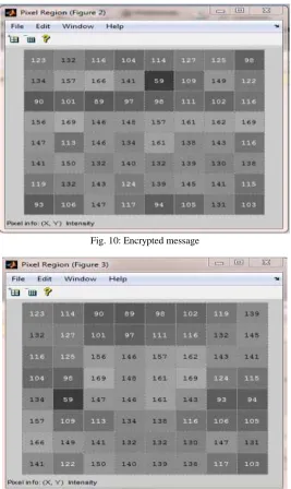
In fig 10 the authentication message used is given. After encrypting using a key the baker mapped message is included in the fig 11. At the receiver the decrypted message is given in the figure 11. When compare the fig 10 and 11 both are same so the data is authenticated.
Fig. 10: Encrypted message
Fig. 11: Decrypted message
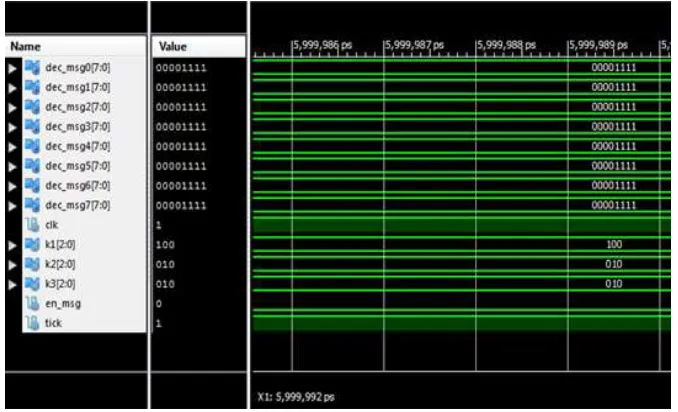
Fig. 13: Decrypted output in verilog
VII. CONCLUSION
Successfully designed and made hardware of SDR transceiver. Provided an authentication message along with audio signal with encryption using baker mapping. And checked and verified the authenticity of transmitted data.Security can be made strong by increasing number of keys and size of the authentication message. Another watermarking scheme can be included to provide better security
REFERENCES
[1] Nie Yang, Ge Hua, Jing Li-li,and Zhao Peng-yu“Model Based Design methodology for digital up and down convertion of Software Defined Radio”
international journal for multimedia and unbiquitous engineering, vol.11,pp.27-36.
[2] A.I Mecwan, N. P. Gajjar “Implementation of Software Defined Radio on FPGA”, Institute of technology, Nirma University, ahmedabad, 2011.
[3] Anton S. Rodriguez, Michael C. Mensinger Jr., In Soo Ahn, and Yufeng Lu “Model-based Software-defined Radio(SDR) Design Using FPGA” Department
of Electrical and Computer Engineering Bradley University 2011.
[4] Jobin Varghese ,Luxy Mathews ,”Low Power Area Optimized Novel Architecture for Software Defined Radio in FPGA” 2014. IEEE International Conference
on Advanced Communication Control and Computing Technologies.
[5] M. A. M. El-Bendary, A. Haggag, F. Shawki, and F. E. Abd-El-Samie, “Proposed Approach for Improving Bluetooth Networks Security through SVD Audio
Watermarking “2012 IEEE, pp-594-598.
[6] Feng HUANG, Yong FENG,” Security analysis of image encryption based on two dimensional chaotic maps and improved algorithm”2009, pp-5-9.
[7] Jiri fridrich, “Symmetric ciphers based on two-dimensional chaotic maps”1998, pp-1259-1284.
[8] B. Macq, J. Dittmann, and E. J. Delp, “Benchmarking of Image Watermarking Algorithms for Digital Rights Management”, Proceedings of The IEEE, Vol.