DTMF Controller based Home Automation
without using Microcontroller
Chandana S Dhongade K H Shivakumar
Department of Electrical & Electronics Engineering Department of Electrical & Electronics Engineering Rao Bahadur Y Mahabaleswarappa Engineering College,
Ballari, India
Rao Bahadur Y Mahabaleswarappa Engineering College, Ballari, India
Saima Sabrin Jayasimha D
Department of Electrical & Electronics Engineering Department of Electrical & Electronics Engineering Rao Bahadur Y Mahabaleswarappa Engineering College,
Ballari, India
Rao Bahadur Y Mahabaleswarappa Engineering College, Ballari, India
Smt. Anusuya Patil
Department of Electrical & Electronics Engineering
Rao Bahadur Y Mahabaleswarappa Engineering College, Ballari, India
Abstract
This paper is about controlling the home appliances from anywhere around the world. This also helps for the people who are physically challenged so that they can operate the appliances in the home using mobile phone. Sometimes there may be chance, to forget to switch off the appliances at home and there may the wastage of power. So, the solution for the above problem is DTMF (Dual Tone multiple Frequency) controlled home automation. The DTMF based automation is controlled by the mobile signals. Using a DTMF technique, the DTMF decoder is connected to the relay which is controlled by the mobile phone by making a call to the other mobile phone which is attached to the DTMF decoder. Thus the home appliances are controlled using DTMF decoder output using mobile phone without using microcontroller.
Keywords: DTMF Decoder, Mobile Phone, Appliances
________________________________________________________________________________________________________
I. INTRODUCTION
Robotics is playing a vital role in automation. People began to introduce the robots during the Industrial revolution which made the industries to reach more productivity with less human interference. One among the intelligent creation of robotics is automation [1].
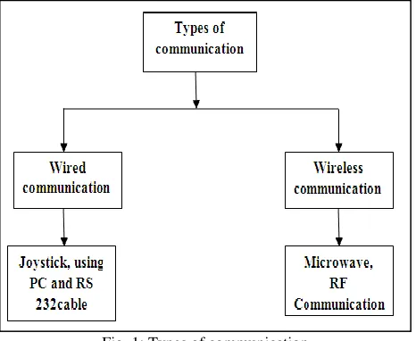
Fig. 1: Types of communication
There are many ways of controlling the home appliances using automation like using micro waves, infrared rays and RF communication which comes under wireless communication.
RF Communication: Wireless communication involves the electromagnetic spectrum, which has many unique qualities. Radio waves propagate according to the spectrum’s wavelength.
Limitations: The above techniques may have draw backs like maintaining line of sight, short distance communication, limited working range and control.
The automation can also be done using wired communication like using Joystick, using PC and RS 232 cable. But the above robotic platform has an imperfection due to the usage of wires having propagation delay. To overcome the above inconvenience of the above mentioned techniques of both wired and wireless communication DTMF (Dual Tone Multi Frequency) came in to the existence where the home appliances are controlled using mobile phone. DTMF provides dominance of robust control, working range as large as the coverage area of the service provider and no interference with other controllers [2].
II. ARCHITECTURE OF DTMF DECODER DTMF DECODER (MT8870 IC)
The DTMF decoder IC [3] offers miniature, low power and high performance. DTMF stands for dual tone multi frequency. The DTMF tone is generated by adding or subtracting two frequencies. This DTMF (Dual Tone Multi Frequency) decoder circuit identifies the dial tone from the telephone line and decodes the key pressed on the mobile phone.
Fig. 2: Frequency group
Based on the key pressed on the mobile phone a low frequency and a high frequency are mixed and a tone is generated called dual tone. The decoder decodes and produces the output in four bit digital format by which the appliances are controlled.
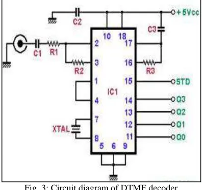
Fig. 3: Circuit diagram of DTMF decoder
The MT8870 is a DTMF receiver having both band split filter and decoder functions. The filter section uses switched capacitor techniques for high and low group filters. The tone may differ due to the noise considerations to overcome that an extra resistor is added so that the different tone can be set to different values. The decoder uses digital counting techniques to detect and decode all 16 DTMF tone pairs in to a 4-bit code.
Crystal Oscillator:
Fig. 4: Crystal Oscillator 3.579545 MHz
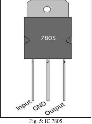
IC 7805:
IC 7805 belongs to 78xx series voltage regulators. It is a linear voltage integrated circuit and has 5-v at the output to maintain fluctuations. These can support an input voltage from around 2.5 volts over the intended output voltage up to maximum of 35 to 40 volts and provide typically 1- 1.5 amperes of current.
Fig. 5: IC 7805
The major components which are used for DTMF based home automation is discussed in the previous section. The block diagram and flow chart of DTMF based home automation will be discussed in the further section.
III. BLOCK DIAGRAM AND FLOWCHART
Fig. 6: Block Diagram of DTMF based home automation
controls the devices at the output. Thus, home appliances are controlled in a simple way by using DTMF decoder without using micro controller.
Flow Chart:
Fig. 7: flowchart determining DTMF based automation
The automation starts when the user at the transmitting end makes the call. If the mobile phone at the receiver received the call, then the signal is processed by the DTMF decoder. The DTMF decoder adds the two frequencies i.e. high frequency group and low frequency group and produces the binary output according to the input applied by the user at transmitting end. If the mobile phone at the receiver gets no input, then there will be no process done by the DTMF decoder and gets stopped.
IV. RESULTS AND FUTURE SCOPE
In this paper we introduced DTMF technology and explained the results based on the appliances connected at the output if the decoder IC[5].
Table – 2
Home appliances used in the Circuit Device 1 LED(Pin 14 ) Device 2 Fan(Pin 13) Device 3 Bulb(Pin 12) Device 4 Buzzer(Pin 11)
From the above fig the devices get operated according to the input applied from the mobile phone keypad from the transmitter. If the user presses „1‟ on his keypad, device connected to the pin 11 gets activated. Likewise when the user presses “2‟ on his keypad, device connected to the pin 12 gets activated. When the user presses “4‟ on his keypad, device connected to pin 13 gets activated. Similarly, when the user presses „8‟ on his keypad device connected to pin 14 gets activated.
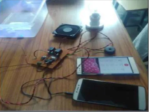
Here are some of the results showing the DTMF based home automation. The automation is done by connecting buzzer to pin 11, bulb to pin 12, fan to pin 13 and LED to pin 14 of DTMF decoder MT8870.
.
From the above figure since the user had pressed 2 on his mobile phone at the transmitter side the device connected to pin 12 i.e. bulb got controlled. Similarly, if the user had pressed 1 on his mobile phone the device connected to pin 11 (buzzer) would have been controlled.
From the above figure since the user had pressed 4 on the mobile phone, the device connected to pin 13 got controlled. Similarly if the user had pressed 8 the device connected to pin 14(LED) would have been controlled.
V. CONCLUSION
REFERENCES
[1] T.Sairam Vamsi, Ramya P, Dr.G.R.L.V.N.S Raju, “Design of Intelligent Accident avoiding system using GPS and GSM ” in International Journal of Modern Trends in Science and Technology (IJMTST) ISSN:2455-3778, Volume-03, Issue-07, pp.310-314.
[2] T.Sairam Vamsi, R.Viswanadam, K.Praveen kumar“An Industrial Survivalence Sensoric robot controlling through Arduino and GSM ” in International Journal of Contol Theory and Applications (IJCTE) Scopus Indenxed with ISSN:0974-5572, Volume-9, Issue- 23, pp.87-96.
[3] T.Sairam Vamsi, K.Radha “ARM Based Stair Climbing Robot Controlling Through DTMF Technology", in International Journal of Recent Technology and Engineering (IJRTE) ISSN: 2277-3878, Volume-2, Issue-3, July 2013, pp. 71-74.