An Optimized Intensity based Data Hiding in
Mosaic Images using Diffie-Hellman Algorithm
for Key Exchange
Shyama Nair V.S Vishwanath N
Assistant Professor Professor
Department of Computer Science Department of Computer Science
KMM College of Arts and Science Thrikkakkara, Ernakulam Toc H Institute of Science & Technology Ernakulam, India
Abstract
Here we implement a secure data transmission technique using an advanced version of Steganography known as the Mosaic Image Steganography (MIS). The technique is implemented using two images as inputs, a cover image in which the secret information is hidden and a target image. Both the images are fragmented and a mosaic image is generated from them. The mosaic image looks similar to the pre-selected target image. The target image is chosen arbitrarily without using any image database. The cover image recovery information is embedded into the mosaic image after encrypting it with a key. The key is generated by the sender and the receiver using the Diffie-Hellman key exchange technique. Since the same key is generated by both parties using this technique, it need not be transmitted by the sender to the receiver. Hence the security issues raised during key transmission can be avoided. After embedding the recovery informations into the mosaic image, it is sent to the receiver. At the receiver side, the image recovery informations are extracted first. Using the informations, the cover image is obtained and hence the data. The technique is found to give good results and is feasible.
Keywords: OIBDH Algorithm, Steganography, Mosaic Images, Key Generation, Encryption, Diffie-Hellman
________________________________________________________________________________________________________
I. INTRODUCTION
We know that development in Internet technology is rising more rapidly. With the rise in multimedia, people find it convenient to communicate using multimedia data. This gave rise to many security issues. Many techniques were thus developed by research scholars in order to find the best solution to this problem. The existing techniques include Steganography, watermarking, cryptography, encryption, visual cryptography etc. Steganography is a technique of hiding a piece of data into an image, audio, or video. Watermarking is a technique to hide digital information in a carrier signal. The hidden information need not contain a relation to the carrier signal. It is prominently used for providing an ownership or a copyright to a document and for authentication. Cryptography is a technique by which a secret data is changed into a meaningless file with the help of key. Steganography and cryptography are different in the sense that the cryptography [2] keeps the contents of a message secret whereas Steganography focuses on keeping the message secret. Once the presence of hidden information is identified, then the purpose of Steganography is partial. Visual Cryptography is a cryptographic technique which is quite easy to implement using two transparent sheets. The image is divided into two parts one among them being the key. The decryption does not require a computer. Each technique has its own significance in the secure transmission of multimedia data. Most of the techniques use data hiding and encryption to hide the secret information. The drawback of such methods is that the process results in meaningless files. These meaningless files arouse attraction to the attackers, meaning the attackers realize that some secret information is hidden in the file. They may hence try out various hacking techniques to retrieve the hidden information.
The second security issue lies in the generation and transmission of key. Security should also be provided to the key since it is also considered as secret information. A technique should therefore be developed in order to avoid the above mentioned drawbacks.
II. OBJECTIVE
III. PROPOSED SYSTEM
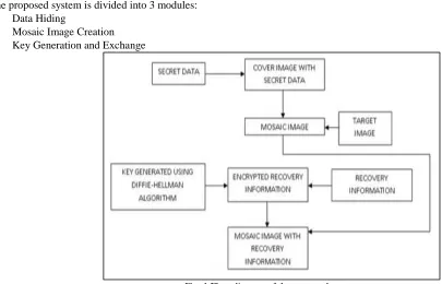
The proposed system is divided into 3 modules: Data Hiding
Mosaic Image Creation Key Generation and Exchange
Fig. 1 Flow diagram of the proposed system
Data Hiding
In this module, we hide a data into an image [6]. The image is known as cover image. Many data hiding techniques are now available in the recent world. Some of them include the LSB technique [7], data hiding in halftone images [11],
Optimized Bit
Plane Splicing algorithm for data hiding in images etc.
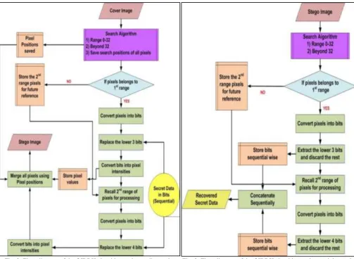
After a comparative study of these techniques we come to a conclusion that the Optimum Intensity based Distributed Hiding algorithm (OIBDH) [12] is best suited for the proposed system because of the reason that follows: In case of Bit Plane Splicing LSB a single secret bit and its nearest adjacent bit are hidden in adjacent pixels since the secret data are embedded in a sequential manner. But in case of OIBDH, if the first bit is hidden in plane q and in pixel w then the next bit is hidden in the similar plane but in a different pixel in the cover image and not necessarily in the adjacent pixel as the next pixel with same intensity value could be located anywhere in the image.This makes the technique more secure than the other data hiding techniques.In the Optimum Intensity Based Distributed Hiding (OIBDH) algorithm as in case of Bit Plane Splicing LSB the lower bits are used to hide secret bits but in a different manner. Instead of hiding bits pixel by pixel and plane after plane the bits are hidden based on the color intensity of a pixel. Here we choose two levels of intensity. For the intensity of pixels between 0−32, the lowest 3 bits are used for hiding secret bits whereas for pixels having intensity of more than 32, only the lower 4 bits are used. By performing heuristic testing with different range of values and searching algorithm we have come up with this optimum range. This range is a near optimum range and causes least degradation when it comes to overall images. This distribution is done based on the weight of pixel and its degradation severity (i.e. the human visual perception due to transition of pixel intensity from one level to another). In addition, since bright intensity levels are more sensitive when transition takes place and dark levels are less sensitive, we have chosen less number of bits for hiding in brighter pixels and higher in darker pixels.
In this way the secret data is distributed throughout the image based upon the color intensity of pixels which is random for every image. In addition, those pixels having intensity levels between 0−32 are used first for data insertion followed by the second range of pixels. Note that not only the bits are hidden randomly in pixels but also the planes are traversed in a non-sequential manner and not plane by plane as in the case of Bit Plane Splicing LSB technique.
Fig. 2: Flow diagram of the OIBDH algorithm at the sending end Fig. 3: Flow diagram of the OIBDH algorithm at the receiving end
Mosaic Image Creation
In this module, we create a mosaic image [5] from the cover image and an arbitrarily selected target image. No image database is used for the selection of the target image. The mosaic image creation phase is further divided into 5 modules:
Transformation of color characteristics between blocks
The cover image in which the secret message is hidden is divided into segments where each segment is called a tile image. A pre-selected target image chosen to hide the cover image is also divided into fragments where each fragment is called a target block. Let each tile image be measured as a set of pixels 𝑃𝑡𝑖𝑙𝑒= {𝑝1 , 𝑝2 ,𝑝3 , …… , 𝑝𝑛 } and each target block as a set of pixels
𝑃𝑡𝑎𝑟𝑔𝑒𝑡 = {𝑝1′ , 𝑝2′ , 𝑝3′ , …… , 𝑝𝑛′ }. Each pixel of the tile image is represented as 𝑝𝑖 (𝑟𝑖,𝑔𝑖, 𝑏𝑖) and each pixel of the target block is represented as 𝑝𝑖′ (𝑟𝑖′,𝑔𝑖′,𝑏𝑖′). We now calculate the mean and standard deviation of these pixels using the formulae:
𝜇𝑐 = 1
𝑛∑ 𝑐𝑖
𝑛
𝑖=1 𝜇𝑐′ = 1
𝑛∑ 𝑐𝑖
′ 𝑛
𝑖=1 (1)
𝜎𝑐= √ 1
𝑛∑ (𝑐𝑖− 𝜇𝑐) 2 𝑛
𝑖=1 𝜎𝑐′= √ 1
𝑛∑ (𝑐𝑖
′− 𝜇 𝑐′)2 𝑛
𝑖=1 (2)
Here, 𝑐𝑖 and 𝑐𝑖′ signify the color channel values of pixels 𝑝𝑖 and 𝑝𝑖′ respectively where c = r, g or b. The new pixel value
𝑝𝑖′′(𝑟𝑖′′, 𝑔𝑖′′, 𝑏𝑖′′) calculation is done using a formula:
𝑐𝑖′′= 𝑞𝑐(𝑐𝑖− 𝜇𝑐) + 𝜇𝑐′ (3)
Where 𝑞𝑐 is known as the standard deviation quotient and is calculated by using the equation 𝑞𝑐 = 𝜎𝑐′/𝜎𝑐. It is seen that the new mean and standard deviation of the resulting tile image is same as that of the target block. The original color values of the pixels are calculated by the reverse operation:
𝑐𝑖= 1/𝑞𝑐(𝑐𝑖′′− 𝜇𝑐′) + 𝜇𝑐 (4) Choosing appropriate target block to fit the tile image
{𝑡𝑎𝑟𝑔𝑒𝑡1, 𝑡𝑎𝑟𝑔𝑒𝑡2, 𝑡𝑎𝑟𝑔𝑒𝑡3, … . . 𝑡𝑎𝑟𝑔𝑒𝑡𝑛} in the ascending order of the average values of standard deviations calculated earlier. Lastly, we fit the first tile image of the set i.e., 𝑡𝑖𝑙𝑒1 into the first target block in the set i.e., 𝑡𝑎𝑟𝑔𝑒𝑡1, the second tile image into the second target block and so on. Since the difference in the standard deviations among the tile image and the target block is minimum, we require only a few transformations in order to transform the tile image into the target block.
Rotation of blocks to fit better with minimum RMSE
Even after performing the color transformations on the tile image, it may not perfectly fit the target block. To avoid the minor distortions, we rotate the resulting tile image into any of the four angles0°, 90°, 180°or 270° which gives the least root mean square error (RMSE) value.
Managing overflows and underflows
After performing the color transformations on the pixels, some of the pixels may have underflows or overflows. An underflow occurs when a particular pixel value is below 0 and an overflow occurs when a particular pixel is above 255. We first convert the pixels above 255 to 255 and the pixels below 0 to 0. Then we calculate the difference between the original values of the pixels and the converted values and note them as residual values. The pixels in the bound of 0 and 255 will thus have a residual value of 0. These values are later used for the recovery of the image. To determine the number of bits needed to represent the residual values we use a different approach. Using two formulae we calculate the smallest possible value in the tile image that is larger than 255, and the largest possible value that is smaller than 0.
cS= ⌈( 1
qc) (255 − μc ′) + μ
c⌉ (5)
cL= ⌈( 1
qc) (0 − μc ′) + μ
c⌉ (6) Next, the residual values are calculated as follows:
|𝑐𝑖− 𝑐𝑆| for an underflow value of 𝑐𝑖 |𝑐𝐿− 𝑐𝑖| for an overflow value of 𝑐𝑖
Thus all the possible values of residuals will range from 0 to 255. Hence we require 8 bits to represent them. Embedding the recovery information
In order to recover the image from the created mosaic image, the receiver requires the image recovery information. Thus we embed the recovery information also into the mosaic image so as to recover it during decryption. For this purpose, we use the LSB technique which was earlier used for data hiding. Here, instead of using the normal LSB technique, we apply a simple transformation on the pixels before embedding them. Specifically, let P (x, y) be a pixel pair which is transformed into P’ (x’, y’) using the formulae:
x’=2x-y, y’=2y-x (7) x=⌈2
3𝑥 ′+1
3𝑦′⌉, y= x=⌈ 1 3𝑥
′+2
3𝑦′⌉ (8)
This technique yields high data hiding capacity compared to the normal LSB technique and the complexity is low. The information hidden into the mosaic image for later recovery of the cover image includes:
The index of the target block
The optimal rotation angle of the tile image
The means and standard deviation quotient of tile and target block The residual values
This information is integrated to form a stream of bits:
M=𝑡1𝑡2… . . 𝑡𝑚𝑟1𝑟2𝑚1𝑚2… … 𝑚48𝑞1𝑞2… . . 𝑞21𝑑1𝑑2… … 𝑑𝑘
Here, 𝑡1𝑡2… . . 𝑡𝑚 represents the index of the target block, 𝑟1𝑟2 indicates the optimal rotation angle of tile image,
𝑚1𝑚2… … 𝑚48 represents the mean of tile and target block in which the mean of n pixels in one color value uses 8 bits.
𝑞1𝑞2… . . 𝑞21 indicates standard deviation quotient in which the value in a single color channel uses 7 bits. 𝑑1𝑑2… … 𝑑𝑘 indicates the residual values of the pixels.
a)Algorithm Mosaic Image Creation
Input: Image in which data is hidden (cover image) and target image. Output: Mosaic image
Steps
1) Step 1: Divide the cover image into blocks where each block is known as tile.
2) Step 2: Similarly, divide the target image into blocks where each block is called a target block. 3) Step 3: The mean and standard deviation of each tile and target block is calculated using formulae.
4) Step 4: Arrange the tile images and the target blocks in the increasing order of average values of their standard deviations. 5) Step 5: Embed the first tile image in the set to first target block with minimum standard deviation variations.
6) Step 6: Rotate the tile image to an angle with minimum RMSE value.
7) Step 7: Calculate the residual values of the pixels with underflow and overflow.
8) Step 8: Generate a stream of bits that contain the recovery information which include the index of the target block, mean and standard deviation of tile and target block, rotation angle and the residual values.
9) Step 9: Encrypt the recovery information using a secure key.
b)Algorithm Cover Image Recovery
Input: Mosaic image with recovery information Output: Cover image
Steps:
1) Step 1: Extract the bit stream M by a reverse version of the scheme proposed and decodes them to obtain the data items. 2) Step 2: Recover one by one in a raster-scan order the tile images of the desired cover image by the following steps:
Step 2.1: Rotate in the reverse direction the block through the optimal angle θ and fit the resulting block content to form the initial tile image.
Step 2.2: Use the extracted means and related standard deviation quotients to recover the original pixel values in the tile image.
Step 2.3: Use the extracted means, standard deviation quotients the equations to calculate cS and cL.
Step 2.4: Scan the tile image to find out pixels with values 255 or 0 which indicate that overflows or underflows respectively have occurred there.
Step 2.5: Add respectively the values cS and cL ; to the corresponding residual values of the found pixels. Step 2.6: Take the results as the final pixel values, resulting in a final tile image.
3) Step 3: Compose all the final tile images to form the desired cover image as output. Key Generation and Transmission
The recovery information required to recover the cover image and hence the data should be encrypted before it can be embedded into the mosaic image. The encryption is done with the help of keys. In most of the encryption techniques, there is a matter of how to send the key to the receiver [8]. Since key is also a secret data, it should reach the receiver without the intervention of the intruder. Here we implement a Diffie-Hellman [9], [10] technique to generate the key. Since the same key is generated by the receiver, it need not be transmitted by the sender. Hence security issues during key transmission can be avoided.
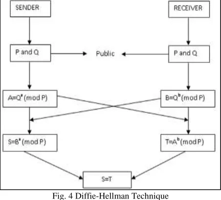
Fig. 4 Diffie-Hellman Technique
The sender chooses a prime number P and Q a primitive root modulo P. The numbers P and Q are shared with the receiver, meaning they are transmitted to the receiver without providing any security. Hence the values are publically known. The sender then calculates A=Qa (mod P)where ‘a’ is the secret key chosen by the sender. The sender sends A to the receiver. Thus, after the first transmission, receiver receives 3 values P, Q and A. Similarly the receiver calculates B=Qb (mod P) where ‘b’ is the secret key chosen by the receiver. The receiver sends B to the sender. Using the value B, the sender calculates S=Ba (mod P). S is used by the sender as the key to encrypt the recovery informations. After encryption, the informations are embedded into the mosaic image and then sent to the receiver. Then the receiver first generates the key using the value A which was sent by the sender using the formula T=Ab (mod P). The key generated is similar to that generated by the receiver, i.e., S=T. Thus there is no security issue in transmitting the secret key to the receiver.
IV. RESULTS AND OBSERVATIONS
(A) (B) (C) (D)
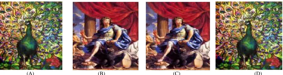
Fig. 5: Experimental results of the proposed method. (A) Cover image (B) Target image (C) Mosaic image created with tile image size 8x8 (D) Recovered cover image using a correct key with RMSE=0.948
The tile image size is 8x8. We can see that the Fig. 5(C) and 5(B) are similar to each other. Similarly the Fig. 5(D) looks nearly identical to the original cover image shown in Fig. 5(A) with RMSE = 0.948 with respect to the cover image. Moreover, in Fig. 6, we see that a wrong key is used to recover the image. Thus we obtain a noise image.
Fig. 6: Recovered cover image using a wrong key
The data embedding process is also found to give good results. Only after obtaining a correct permutation of the tile image, can a receiver get back the original message from it. The OIBDH algorithm is reversible as the secret data is recovered properly. Note that we are assuming the received image contains no noise or impairments due to transmission channel. In order to protect the stego image from channel induced interference, channel encoding and modulation techniques can be used.The data retrieved using the correct key is shown in Fig. 7.
Fig. 7: Data recovered using the correct key
To test the accuracy in decryption, we compare the recovered cover image with the original one. From Fig. 8 we can find out that the RMSE value of both the images does not have much variation.
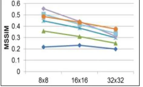
To measure the mosaic effect, we adopt the metric of mean structural similarity (MSSIM) to compare the similarity of the created mosaic image and the target image. Fig. 9 shows the MSSIM values of the mosaic images created in perspective of the target images versus different tile image sizes, where the window size for computing the MSSIM is set to be the same as the size of the tile image. The MSSIM value of the created mosaic image with respect to the target image varies from 0.2 to 0.8, which shows that the resemblance of the details of the mosaic images created to those of the target image is not fine enough. But, this is not the main concern of the proposed method because the goal is to create a globally visually similar mosaic image, which contains a cover image of the same size, for the purpose of secure image transmission.
Fig. 9: MSSIM values of created mosaic images with respect to target images
Next, we compare the existing Steganography technique with the proposed system. Fig. 10 shows the result of this comparison. As we can see, the Mosaic Image Steganography technique has less image distortions compared to the normal Steganography technique. Thus the accuracy of the proposed system is more than the existing system.
Fig. 10: Comparison of the Mosaic Image Steganography technique with respect to the existing Steganography technique.
Table – 1
Comparison of the proposed system with respect to existing technique using RMSE value image size Steganography mosaic image Steganography
64X64 0.4490 0.021
128X128 0.2419 0.0185
256X256 0.1839 0.0168
512X512 0.1810 0.0151
In the proposed system we use three transmissions in total. Two transmissions during the execution of Diffie-Hellman algorithm and one transmission for the mosaic image. Hence the time required for the completion of the process is more compared to the existing Steganography technique. But the fact is negligible in perspective of the high security the proposed system provides.
V. SECURITY CONSIDERATIONS
on such huge digits. The next secure aspect is that only the receiver who knows the key can get the recovery information. Once he obtains the recovery information, he can extract the cover image and data using this information. However, an attacker may try all the possible permutations to get back the cover image and hence the data. But, the number of possible permutations is n! , hence the probability for an eavesdropper to find the correct permutation is p=1/n! which is a very small value. Hence breaking the system in this manner is practically infeasible.
VI. CONCLUSION
The various drawbacks found in the surveys done so far have brought in an idea of introducing a new technique where the data hiding and image transmission is combined to a single module. The data is first hidden into a cover image using the OIBDH algorithm. The image is then divided into small fragments and embedded into a pre-selected target image. The resultant image is known as mosaic image. No image databases are used in this technique for the selection of target images. The image recovery information is also embedded in the mosaic image after encrypting it using a key. The security is further enhanced by implementing a Diffie-Hellman key exchange algorithm for the generation and transmission of key. The mosaic image is recovered using the recovery information. From the mosaic image the cover image and thus the secret data is obtained by performing the reverse operations.
ACKNOWLEDGEMENT
We would like to thank all the reviewers for many useful comments and feedbacks that improve the paper presentation.
REFERENCES
[1] Chia-Chen Lin, Yi-Hui Chen and Chin-Chen Chang,“LSB-Based High-Capacity Data Embedding Scheme For Digital Images”, International Journal of Innovative Computing, Vol.5, November 2009.
[2] William Stallings, ”Overview”, in Cryptography and Network Security, 5th edition, Pearson Education, Inc, 2006, ISBN 10: 0-13-609704-9.
[3] Ya-Lin Lee and Wen-Hsiang Tsai, “A New Secure Image Transmission Technique via Secret-fragment-visible Mosaic Images by Nearly-reversible Color Transformations”, IEEE Transactions on Circuits and Systems for Video Technology, Vol. 24, No. 4, April 2014.
[4] Soumi C.G, Joona George and Janahanlal Stephen, "Genetic Algorithm based Mosaic Image Steganography for Enhanced Security", ACEEE Int. J. on Signal and Image Processing, Vol. 5, No.1, January 2014.
[5] I-Jen Lai and Wen-Hsiang Tsai,”Secret-Fragment-Visible Mosaic Image–A New Computer Art and Its Application to Information Hiding”, IEEE Transactions on Information Forensics and Security, Vol. 6, No. 3, September 2011.
[6] N.S. Soleimani Zakeri and M.A. Balafar, “ A Review on Data Hiding upon Digital Images”, International Journal on Technical and Physical Problems of Engineering.
[7] Chi-Kwong Chsn and L.M Cheng, “Hiding Data in Images by Simple LSB Substitution “, Pattern Recognition, August 2003.
[8] Er. Lalit Kumar, Er. Vikas Rana and Er. Akash Rana, “An Algorithm for Secure Key Distribution and Data Transfer in MANETS”, International Journal of Advanced Research in Computer Science and Software Engineering, Vol. 3, Issue 4, April 2013.
[9] Rohini, Er. Meenakshi Sharma, “Enhancing the Diffie-Hellman algorithm”, International Journal of Advanced Research in Computer Science and Software Engineering, Vol. 4, Issue 6, June 2014.
[10] Maryam Ahmed, Bahran Sanjabi and Difo Aldiaz, “Diffie-Hellman and its application in Security Protocols”, International Journal of Engineering Science and Innovative Technology, Vol. 1, Issue 2, November 2012.
[11] Harshavardhan Kayarkar, Sugata Sanyal, “A Survey on Various Data Hiding Techniques and their Comparative Analysis”, Tata Institute of Fundamental Research.