FPGA Implementation Of Low Area Single
Precision Floating Point Multiplier
Mamatha M S Pramod Kumar
PG Scholar Assistant professor
Department of Electronics & Communication Engineering Department of Electronics & Communication Engineering
KIT, Tiptur, India KIT, Tiptur, India
Abstract
In this paper depict an effective usage of an IEEE 754 single precision floating point multiplier focused for Xilinx Spartan 3E FPGA. Verilog HDL is utilized to actualize an innovation. The multiplier execution handles the overflow and underflow cases. Adjusting is not actualized to give more accuracy when utilizing the multiplier as a part of a multiply and Accumulate (MAC) unit. The multiplier was confirmed against Xilinx floating point multiplier center produced by Xilinx coregen. By using 24*24 Nikhilam vedic sutra for multiplication reduces the area of proposed design, It reduces the large multiplying numbers into smaller values.
Keywords: floating point; multiplication; FPGA; vedic multiplier (VM)
________________________________________________________________________________________________________
I. INTRODUCTION
Floating point numbers are one conceivable method for speaking to genuine numbers in binary configuration; the IEEE 754 [1] standard presents two diverse floating point designs, Binary interchange format and Decimal interchange format. Increasing floating point numbers is a basic prerequisite for DSP applications including substantial element range. This paper concentrates just on single precision standardized binary interchange design. Fig. 1 demonstrates the IEEE 754 single precision binary configuration representation; it comprises of a one piece sign (S), an eight piece example (E), and a twenty three piece portion (M or Mantissa). An additional piece is added to the division to frame what is known as the significand1. On the off chance that the example is more noteworthy than 0 and littler than 255, and there is 1 in the MSB of the significand then the number is said to be a normalized number; for this situation the genuine number is spoken to by (1)
Fig. 1: IEEE single precision floating point format
Z = (-1S) * 2 (E - Bias) * (1.M) (1) Where M = m22 2-1 + m21 2-2 + m20 2-3+…+ m1 2-22+ m0 2-23;
Bias = 127.
Increasing two numbers in floating point configuration is finished by 1-including the example of the two numbers then subtracting the inclination from their outcome, 2-duplicating the significand of the two numbers, and 3-computing the sign by XORing the indication of the two numbers. Keeping in mind the end goal to speak to the augmentation result as a standardized number there ought to be 1 in the MSB of the outcome (driving one).
Floating point usage on FPGAs has been the enthusiasm of numerous scientists. By taking my previous research paper as base paper implemented the low area single precision floating point multiplier in this review work by using Nikhilam Vedic Sutra for 24 bit mantissa multiplication. A 24x24 bit Nikhilam Sutra multiplier architecture is utilized as it has a moderate rate with a basic design. Nikhilam sutra or technique from vedic arithmetic to perform effective augmentation for little inputs. Nikhilam sutra performs vast increase by changing over it to little multiplication alongside some expansion and moving operations. The Ancient Indian Vedic Mathematics involves sixteen Sutras and thirteen corollaries. The four rudimentary operations of a processor, the expansion, subtraction, increase and the division have been broadly manage in the sixteen sutras of Vedic Mathematics. The work in this paper includes the Nikhilam which manage the mantissa multiplication.
II. FLOATING POINT MULTIPLICATION ALGORITHM
As stated in the introduction, normalized floating point numbers have the form of
Z= (-1S) * 2 (E - Bias) * (1.M). To multiply two floating point numbers the following is done: 1) Multiplying the significand; i.e. (1.M1*1.M2)
3) Adding the exponents; i.e. (E1 + E2 – Bias) 4) Obtaining the sign; i.e. s1 xor s2
5) Normalizing the result; i.e. obtaining 1 at the MSB of the results’ significand 6) Rounding the result to fit in the available bits
7) Checking for underflow/overflow occurrence
Consider a floating point representation like the IEEE 754 single precision floating point design, however with a lessened number of mantissa bits (just 4) while as yet holding the shrouded "1" bit for standardized numbers:
A = 0 10000100 0100 = 40, B = 1 10000001 1110 = -7.5 To multiply A and B
Multiply significand:
1.0100 × 1.1110
00000
10100
10100
10100
10100
1001011000
Place the decimal point:
10.01011000
Add exponents:
10000100 + 10000001
100000101
The exponent representing the two numbers is already shifted/biased by the bias value (127) and is not the true exponent; i.e. EA = EA-true + bias and EB = EB-true + bias And
EA + EB = EA-true + EB-true + 2 bias
So we should subtract the bias from the resultant exponent otherwise the bias will be added twice. 100000101
- 01111111 10000110
Obtain the sign bit and put the result together:
1 10000110 10.01011000
Normalize the result so that there is a 1 just before the radix point (decimal point). Moving the radix point one place to the left increments the exponent by 1; moving one place to the right decrements the exponent by 1.
1 10000110 10.01011000 (before normalizing) 1 10000111 1.001011000 (normalized) The result is (without the hidden bit):
1 10000111 00101100
The mantissa bits are more than 4 bits (mantissa available bits); rounding is needed. If we applied the truncation rounding mode then the stored value is:
1 10000111 0010.
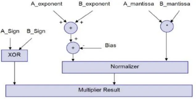
Fig. 2: Floating point multiplier block diagram
III. MODULES OF FLOATING POINT MULTIPLIER
Sign bit calculation
Multiplying two numbers results in a negative sign number if one of the multiplied numbers is of a negative quality . By the guide of a truth table we find this can be acquired by XORing the indication of two inputs.
Unsigned Adder (for exponent addition)
This unsigned adder is in charge of including the example of the principal info to the type of the second input and subtracting the Bias (127) from the addition result (i.e. A_exponent + B_exponent - Bias). The after effect of this stage is known as the intermediate exponent. The add operation is done 8 bits, and there is no requirement for a brisk result in light of the fact that the vast majority of the estimation time is spent in the significand multiplication process (increasing 24 bits by 24 bits); therefore we require a moderate type adder and a quick significand multiplier.
A 8-bit ripple carry adder is utilized to add the two input exponents. As appeared in Fig. 3 a ripple carry adder is a chain of fell full adders and one half adder; every full adder has three inputs (A, B, Ci) and two outputs (S, Co). The carry out (Co) of each adder is fed to the next full adder (i.e each carry bit "ripples" to the next full adder).
Fig. 3: Ripple Carry Adder
The addition process delivers a 8 bit sum (S7 to S0) and a convey bit (Co, 7). These bits are linked to shape a 9 bit expansion result (S8 to S0) from which the Bias is subtracted. The Bias is subtracted utilizing an array of ripple borrow subtractors.
Fig. 4: Subtractor
An ordinary subtractor has three inputs (minuend (S), subtrahend (T), Borrow in (Bi)) and two outputs (Difference (R), Borrow out (Bo)). The subtractor logic can be upgraded on the off chance that one of its inputs is a constant value which is our case, where the Bias is consistent (127|10 = 001111111|2). Table I demonstrates reality table for a 1-bit subtractor with the data T equivalent to 1 which we will call "one subtractor (OS)".
Table – 1
S T Bi Difference (R) Bo
0 1 0 1 1
1 1 0 0 0
0 1 1 0 1
1 1 1 1 1
The Boolean equations (2) and (3) represent this subtractor:
Difference (R) = S ⊕ Bi (2) Borrowout (Bo) = S + Bi (3)
Fig. 5: 1-bit subtractor with the input T = 1
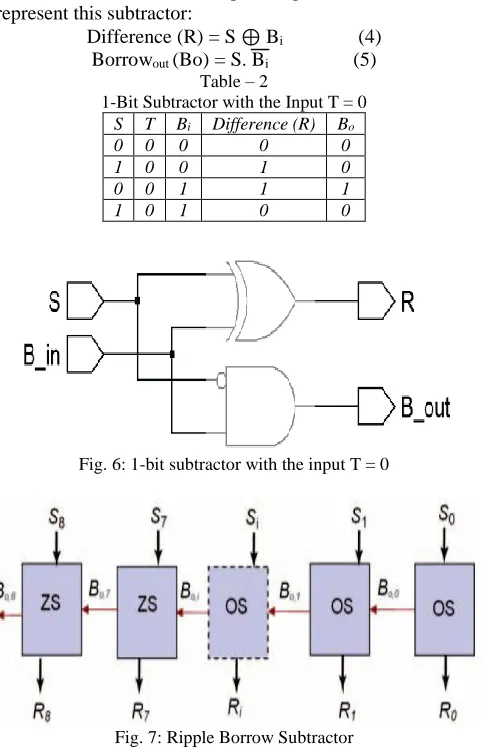
Table II shows the truth table for a 1-bit subtractor with the input T equal to 0 which we will call “zero subtractor (ZS)”. The Boolean equations (4) and (5) represent this subtractor:
Difference (R) = S ⊕ Bi (4) Borrowout (Bo) = S. Bi (5)
Table – 2
1-Bit Subtractor with the Input T = 0 S T Bi Difference (R) Bo
0 0 0 0 0
1 0 0 1 0
0 0 1 1 1
1 0 1 0 0
Fig. 6: 1-bit subtractor with the input T = 0
Fig. 7: Ripple Borrow Subtractor
Fig.7 demonstrates the Bias subtractor which is a chain of 7 one subtractors (OS) trailed by 2 zero subtractors (ZS); the borrow output of each subtractor is fed to the next subtractor. If an underflow happens then Eresult < 0 and the number is out of the IEEE 754 single precision normalized numbers range; for this situation the output is motioned to 0 and an underflow flag is declared.
Unsigned Multiplier (for significand multiplication)
is done on 24 bit. Multiplier execution ought to be thought about so as not to influence the entire multiplier's execution. A 24x24 bit Nikhilam suthra vedic mathematics design is utilized as it has a moderate pace with a simple architecture.
Nikhilam Navatascharam Suthra implies all from 9 and last from 10. This calculation works for all numbers yet it works proficiently for bigger numbers. Since it discovers the compliment of the expansive number from its closest base to perform the increase operation on it, bigger is the first number, lesser the unpredictability of the augmentation. The methodology for Nikhilam sutra is
1) Take the base of computation as force of 10 which is closest to the multiplicands say M and N. 2) Subtract base B from every multiplicand and note two leftovers as say M and N.
3) Section 1 contains the numbers and Column 2 contain distinction from the closest base
4) The item will have two sections. Right part (R) is gotten by increase of two remnants in particular m and n. i.e. R = m x n.
5) Left part (L) can be acquired by cross subtracting the second number of Column 2 from the principal number of section 1 or the other way around.
6) The answer is acquired by simply connecting left and right part as LR. Fig 8. Multiplication using Nikhilam suthra. The decimal point is between bits 45 and 46 in the significand multiplier result. The multiplication time taken by the Nikhilam Suthra multiplier is less and also reduces the complexity of large number multiplication.
96*93 Nearest base =100
96 (96-100) 93 (93-100)
Fig. 8: Multiplication using Nikhilam
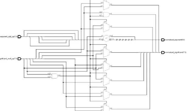
Normalizer
The consequence of the significand multiplication (middle item) should be normalized to have a main "1" recently to one side of the decimal point (i.e. in the bit 46 in the middle item). Since the inputs are normalized numbers then the middle of the intermediate product has the leading one at bit 46 or 47
1) If the leading one is at bit 46 (i.e. to one side of the decimal point) then the intermediate product is as of now a normalized number and no shift is required.
2) If the leading one is at bit 47 then the intermediate product is shifted to the right and the exponent is increased by 1. The shift operation is done utilizing combinational shift logic made by multiplexers. Fig. 9 demonstrates a disentangled logic of a Normalizer that has a 8 bit intermediate product input and a 6 bit intermediate exponent input.
IV. UNDERFLOW/OVERFLOW DETECTION
Overflow/underflow implies that the outcome's type is too large/small to be spoken to in the example field. The type of the outcome must be 8 bits in size, and should be somewhere around 1 and 254 generally the worth is not a normalized one. An overflow may happen while adding the two exponents or amid normalization. Overflow because of example expansion might be repaid amid subtraction of the bias; bringing about an ordinary output value (normal operation). An underflow may happen while subtracting the bias to frame the intermediate exponent. On the off chance that the intermediate exponent < 0 then it's an underflow that can never be adjusted; if the intermediate exponent = 0 then it's an underflow that might be remunerated during normalization by adding 1 to it.
At the point when an overflow happens an overflow flag signal goes high and the outcome turns to ±Infinity (sign decided by indication of the floating point multiplier inputs). At the point when an underflow happens an underflow flag signal goes high and the outcome swings to ±Zero (sign decided by indication of the floating point multiplier inputs). Denormalized numbers are motioned to Zero with the suitable sign figured from the inputs and an underflow flag is raised. Expect that E1 and E2 are the types of the two numbers A and B individually; the outcome's type is calculated by (6)
Eresult = E1 + E2 – 127 (6) Table – 3
Normalization Effect on Result’s Exponent and Overflow/Underflow Detection
Eresult Category Comments
-125 ≤ Eresult < 0 Underflow Can’t be compensated during Normalization
Eresult = 0 Zero May turn to normalized number during normalization (by adding 1 to it) 1 < Eresult < 254 Normalized
number
May result in overflow during Normalization
255 ≤ Eresult Overflow Can’t be compensated
E1 and E2 can have the values from 1 to 254; resulting in Eresult having values from -125 (2-127) to 381 (508 127); but for normalized numbers, Eresult can only have the values from 1 to 254. Table III summarizes the Eresult different values and the effect of normalization on it.
V. IMPLEMENTATION AND TESTING
The entire multiplier (top unit) was tested against the Xilinx floating point multiplier core created by Xilinx coregen. Xilinx core was altered to have two flags to demonstrate overflow and underflow, and to have a maximum latency of three cycles. Xilinx core implements the "round to nearest" rounding mode.
A testbench is utilized to produce the stimulus and applies it to the implemented floating point multiplier and to the Xilinx core then compares the outcomes. The configuration was synthesized utilizing Precision synthesis instrument [8] focusing on Xilinx Spartan 3E.
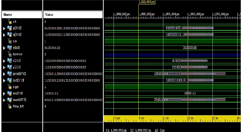
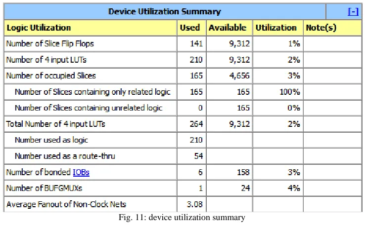
Post synthesis and place and route simulations were made to ensure the configuration usefulness after synthesis and place and route. Table IV demonstrates the resources and frequency of the proposed implemented floating point multiplier, past floating point multiplier and Xilinx core after simulation. Fig 10 shows the simulation result of proposed design by using ISIM. After generate the programming flie the number of slices utilized will displayed in device utilization summary as shown fig 11
Fig. 11: device utilization summary
Table – 4
Area and Frequency Comparison between the Implemented Floating Point Multiplier and Xilinx Core Previous Floating Point
Multiplier Xilinx Core Proposed implemented floating point multiplier
CLB Slices 604 266 41.25
DFF 293 241 96
Function generators 1263 765 264
The Spartan 3E FPGA board has matrix of CLB slices each CLB slices having 4 numbers of slices and number of LUTs is known as function generators [8], by using this conditions in this work calculate the CLB slices and function generators. The area of executed floating point multiplier is smaller than the past floating point multiplier [1] and Xilinx core multiplier furthermore done the truncate/round the 48 bits consequence of the mantissa multiplier which is reflected in the measure of function generators and registers used to perform operations on the extra bits; likewise the speed of Xilinx center is influenced by the way that it actualizes the round to closest rounding mode.
VI. CONCLUSIONS AND FUTURE WORK
This paper shows an execution of a floating point multiplier that backings the IEEE 754-2008 binary interchange format; the multiplier doesn't implement rounding and just exhibits the significand multiplication result as seems to be (48 bits); this gives better precision if the whole 48 bits are used in another unit; i.e. a floating point adder toward structure a MAC unit. The proposed design has low area and function generators compared to previous floating point multiplier and also it takes low cost compare to that. By using improved version FPGA ie. Virtex 5 etc. increased the speed of this proposed design.
ACKNOWLEDGMENT
I would like to thank my parents, god and whose work I have referred as a guiding stone in my dissertation work.
REFERENCES
[1] Mohamed Al-Ashrafy, Ashraf Salem, Wagdy Anis “An Efficient Implementation of Floating Point Multiplier”,IEEE 2011.
[2] B. Fagin and C. Renard, “Field Programmable Gate Arrays and FloatingPoint Arithmetic,” IEEE Transactions on VLSI, vol. 2, no. 3, pp. 365–367, 1994 . [3] B. Lee and N. Burgess, “Parameterisable Floating-point Operations on FPGA,” Conference Record of the Thirty-Sixth Asilomar Conference on Signals,
Systems, and Computers, 2002
[4] L. Louca, T. A. Cook, and W. H. Johnson, “Implementation of IEEE Single Precision Floating Point Addition and Multiplication on FPGAs,” Proceedings of 83 the IEEE Symposium on FPGAs for Custom Computing Machines (FCCM’96), pp. 107–116, 1996
[5] Vedavathi K. And Sitamaha Lakshmi T.“An Iterative Binary Multiplication Algorithm Using Nikhilam Sutra”, International Journal of Current Research Vol. 4, Issue, 10, pp.187-190, October, 2012
[6] Aniruddha Kanhe, Shishir Kumar Das, “Design and Implementation of Floating Point Multiplier based on Vedic Multiplication Technique”, ICCICT, Oct. 19-20, 2012.
[7] Sneha Khobragade1, Mayur Dhait, “Review on Floating Point Multiplier Using Vedic Mathematics”,IJSR ,ISSN (Online): 2319-7064 ,Index Copernicus Value (2013): 6.14 Impact Factor (2013): 4.438