R E S E A R C H
Open Access
A new method for the treatment of
unilateral posterior cross-bite: a
three-dimensional finite element stress analysis
study
Ça
ğ
r
ı
Ulusoy
1*and Merve Dogan
2Abstract
Background:Stress relieving corticoto mies during the treatment of maxillary expansion are needed in adult patients.
Methods:Three-dimensional (3D) finite element model was prepared, and finite element analysis was processed to evaluate the stress distributions within the skull and maxillary teeth during surgically assisted rapid maxillary expansion (SARME) treatment.
Results:Expansion forces generated more stress on the corticotomy-applied part of the maxilla. The stress levels decreased dramatically above the corticotomy line.
Conclusion:Asymmetric transveral maxillary expansion might be achieved from a symmetric force generating screw during SARME treatment. SARME osteotomies may concentrate the stress in the expanding maxilla and reduce the pain in other parts of the cranium.
Background
Posterior cross-bite, which may be occurred by skel-etal, dental, or functional reasons, is one of the most common craniofacial disorders in transversal direction [1]. Unilateral posterior cross-bite is a specific sub-type of this disorder characterized by an arch defi-ciency. It may alter the mandibular growth pattern of the growing subjects and form asymmetric condylar height resulting in facial asymmetry [2].
The patient’s age, the complexity of the disorder due to sagittal and vertical maxillo-mandibular rela-tions, and the presence of other systemic problems should be considered in the treatment planning of unilateral cross-bite [3]. Orthodontic, orthopedic, or combination of orthopedic and surgical skills could be used in increasing the transversal width of the
maxilla. Surgically assisted rapid maxillary expansion (SARME) was one of the most effective methods in the treatment of unilateral cleft palate problem [4]. Paralysis of the nerves, hemorrhage, pain, deviation of the nasal septum, periodontal diseases, and relapse of the treatment were shown among the possible prob-lems which might occur during maxillary expansion without surgical corticotomies [5].
Treatment of unilateral cross-bite was performed by either slow palatal or rapid maxillary expansion, gen-erally resulting in an unwanted overdevelopment of the side that had normal pretreatment transversal re-lation with the mandibular teeth [6, 7]. Therefore, the anchorage performance of the normal side should be increased by suggesting cross elastics to the patient in order to overcome this problem [8].
Three-dimensional (3D) computer-assisted researches became popular in dental field in the past two
* Correspondence:[email protected]
1Department of Orthodontics, Faculty of Dentistry, Gazi University, Emek,
Ankara, Turkey
Full list of author information is available at the end of the article
decades [9, 10]. 3D finite element stress analysis (FESA) is a numeric method for simulating mechanical behaviors of real physical systems and considered to be a valid and reliable approach for calculating stress and displacement of dentoalveolar structures [11]. Yang et al. [12] stated that FEM could be beneficial to simulate orthodontic approaches and to compare their biomechanical effects without increasing num-ber of patients or animals like in the clinical investi-gations. The aim of this study was to evaluate the effects of a new method for unilateral maxillary expansion by using 3D FESA.
Methods
This study was conducted under the approval of Gazi University Institute of Health Sciences and study ma-terial was selected from the archive of Gazi University
Faculty of Dentistry Department of Orthodontics (Approval number 2016/0493). Written informed con-sent of the patient was precon-sent in patients file as a regular procedure. All teeth were present in the mouth of the patient except for the third molars which might have interfered with the osteotomy lines above maxillary tuber region.
The material consisted of computerized tomog-raphy (CT) images of a skeletal class 1 adult patient with normal vertical cephalometric values and with-out any craniofacial anomalies except for unilateral cross bite. The CT images were requested from the patient by Department of Oral-Maxillofacial Surgery of the faculty as a routine procedure for the patients who would undergo surgical/orthognathic treatments. The CT data which consisted of 601 sections in 0.2 mm thickness was obtained by using a cone beam computed tomography (ILUMA, IMTEC Co., Hatfield, PA, USA) in 40 s with 120 kvp, 3.8 mA.
3D finite element model was prepared and finite element analysis was processed with an Intel Xeon com-puter (CPU 3.30 GHz, 14 GB RAM, Intel Co., Santa Clara, CA, USA). Marc software (version 2005; MSC Software, Newport Beach, CA, USA) was used to construct the 3D finite element models for pre-processing and modeling. All the anatomical regions such as cortical bone shell, inner spongeous bone, maxillary sinuses, sutures, teeth, and periodontal ligaments around the teeth roots were modeled (Fig. 1).
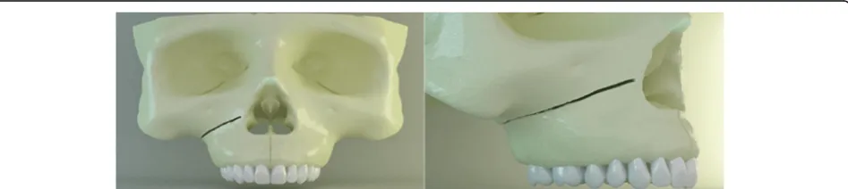
The right side of the study model had an oblique corticotomy line extending from apertura piriformis to pterygopalatinal junction in the posterior, lying be-neath the zygomatic buttress region (Fig. 2) [13–15]. The surgery remained in the cortical layer and did not involve the spongeous bone.
The rapid maxillary expansion (RME) appliance was formed on the plaster copy of the patient’s max-illa. The RME screw (Leone Orthodontics, Firenze,
Fig. 1Cortical bone layer, spongious bone, maxillary sinus, and teeth from the sagittal view
Fig. 2Oblique corticotomy line from frontal and lateral view. The line extends from apertura piriformis to pterygopalatinal junction lying beneath the zygomatic buttress region
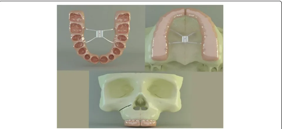
Italy) was set 3 mm above the mid-palatal suture. The appliance was designed as a modified full acrylic cap-splint type RME in order to eliminate the retrac-tion force on the anterior teeth which was com-monly observed during the treatment period with classic acrylic cap-splint RME’s (Fig. 3). The appli-ance was scanned by an optical scanner (Activity 880, Smart Optics Sensortechnik Gmbh, Bochum, Germany), and the images were based to form a 3-D RME model in computer environment by using Rhinoceros 4.0 software (Rhinoceros Inc., Seattle, USA). After the RME model was transferred to com-puter, it was placed onto the occlusal surfaces of the maxillary teeth. The gingival thirds of the teeth crowns, where the acrylic part ended, were left open to achieve periodontal hygiene (Fig. 3). Maxillary teeth and the inner surface of the acrylic part of the RME, which were facing each other, were bounded to simulate the bonding of the appliance to teeth in clinical conditions.
Final solid meshes were constituted by hexahedral (8 noded) elements, if possible, in order to increase the reliability of the model. If a region was too small for an 8-noded element, 7-, 6-, 5-, or even 4-noded (tetrahedral) elements were formed by Marc soft-ware. The model had 183,528 nodes and 863,441 ele-ments in total. All the bone, teeth, and RPE appliance elements were assumed to be isotropic, homoge-neous, and linearly elastic (Fig. 4). The elastic
properties of the materials used in this study were shown in Table 1 [15, 16].
Finite element stress analysis (FESA) was also per-formed with Marc software. The skull model was fixed with 0 degree of freedom (DOF) over the supraorbital region and from the posterior plane in order to overcome unwanted movements, shift, and rotations of the elements during force application (Fig. 5). The blue arrows in opposing directions show the center of force application through the mid-palatal suture. The magnitude of the force generated by the RME appliance was defined as
Fig. 3Inner view of modified full acrylic cap-splint (above left). RME was placed onto the occlusal surfaces of the maxillary teeth (above right). The gingival thirds of the teeth crowns, where the acrylic part of RME ended, were left open to achieve periodontal hygiene (below)
100 N [17]. This experimental setup was designed for easier evaluation and understanding of the stresses gener-ated. Von Mises stresses generated by RME appliance were measured and evaluated by three-dimensional FESA.
Results
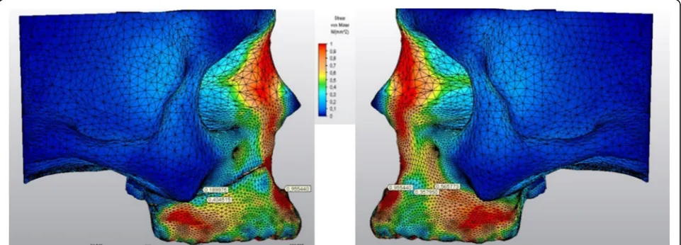
The stress levels in right and left sides of the skull model were generally harmonic except for the re-gions above and below the corticotomy line (Fig. 6). A stress magnitude of 0.40 GPa was recorded below the corticotomy line and stress was dramatically de-clined to 0.18 GPa above this line (Fig. 7). The stress levels in the same points of the non-corticotomy
side were calculated as 0.35 and 0.56 GPa, respectively (Fig.7).
The stressed areas on the tuber, zygomatic but-tress, and pterygoid processes could be seen in Fig. 8 from the occlusal plane. The stress levels were de-clined in the medio-lateral direction both on the right and left maxillary sinus walls (Fig. 8). The highest Von Mises stress levels on some anatomical regions during force application could be seen in Table 2.
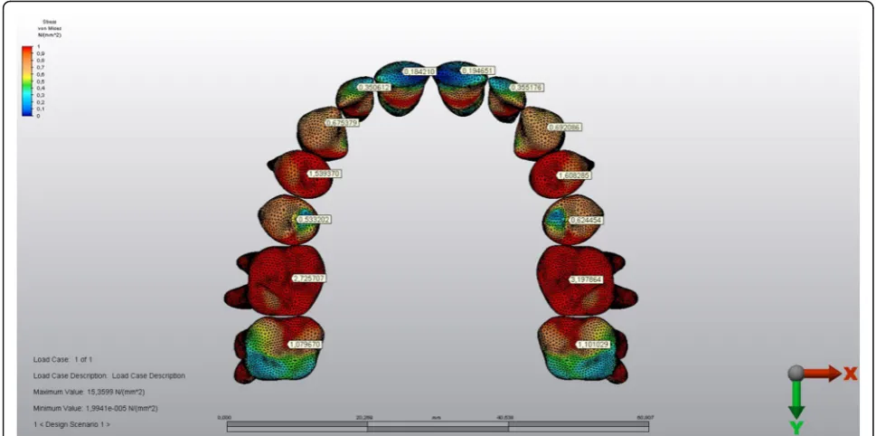
The stress levels of the teeth in the corticotomy side were lower than the other side (Figs. 9 and 10). The magnitude of the stresses calculated on the teeth crowns and the roots of both sides were shown in Table 3.
Discussion
In a bibliographical review about finite element mod-ellings in dentistry, FEM was described as a prevalent and useful technique in the evaluation of stress distri-butions in biomechanic models [18]. During the constitution of FEM models, it was suggested that in-crease in the number of elements and nodes resulted in a more detailed and realistic structure [19]. In the present study, 183,528 nodes and 863,441 elements were used in model construction, which was quite satisfactory when compared with some previous three-di-mensional FEM studies [20,21].
All elements tested in the present FEM study were assumed to be isotropic, homogeneous, and linearly elastic as in the literature [14, 15]. Due to the differences Table 1Elastic properties and Poisson ratio’s of the structures
used in the study
Elastic properties (GPa) Poisson ratio Cortical bone 15 0.30 Spongious bone 1.50 0.30 Teeth 19.6 0.30 Sutures 0.069 0.45 RME appiance (stainless
steel)
200 0.29 Acrylic (polimethyl
methacrilate)
1.80 0.35 Periodontal ligament 0.07 0.45
GPagigapascal,RMErapid maxillary expansion
Fig. 5The skull model was fixed over the supraorbital region and from the posterior plane. (above left and right) The blue arrows in opposing directions show the center of force application through the mid-palatal suture (below)
between the finite element models and the actual situ-ation owing to material properties and boundary con-ditions, the results of the FEM studies should be deciphered with caution. For example, the PDL is a non-linear, viscoelastic, and anisotropic material actu-ally [12]. However, it occupies only a little volume in total skull models in FEM studies and its elastic prop-erties are incomparably minor to dense structures as cortical bone and teeth. Therefore, insignificant as-sumptions like in the current example may form negli-gible effects on the outcomes derived from FEM analysis.
Previous studies have shown that the computed tomographic images are not reliable for generating
detailed 3D models of teeth [13, 22, 23]. Dental age, tooth wear, metabolic calcium content, individual volumetric changes of dental sub-structures, and dif-ference in hardness calibration techniques used to determine elastic properties of the tissues were shown among the factors that avoid the researchers to maintain a specific data for dentin, pulp, and en-amel [24]. Therefore, a single elastic modulus and Poisson ratio data that was derived from previous FEM studies was assigned to teeth in the current study which mainly focused on the effects of unilat-eral corticotomy of the bone model [13, 25].
Every element in nature has an elastic limit under pressure above which the deformations stop being
Fig. 6Frontal view of the stressed areas in the skull model
elastic and irreversible deformation occurs. Von Mises stress is a measure of distortion energy dens-ity at a particular point in a system which is useful in ascertaining failure in ductile materials [26]. Von Mises stress allows researchers to determine the elastic limit for any material easily; therefore, it is commonly used in computer engineering-based diag-nostic experiments [9, 14, 15]. On the other hand, maximum and minimum principle stress values, de-fining the highest tension and highest compression, respectively, can be obtained by suitably rotating an element with no shear stress [26]. In other words, the principle stress is the normal stress that an element will ever see under specified applied loads, like ham-mering a nail in one direction without causing shear
forces. Principle stress could be the right criterion for the FEM studies focusing on mini-screw anchorage and orthodontic tooth movement. Based on the concerns mentioned above, von Mises criterion was chosen in the present study to investigate multi-directional 3D realistic stress occurred during corticotomy applied maxillary expansion.
Rapid maxillary expansion was pointed out to be among the most promising methods in the treatment of transversal maxillary deficiency [27–29]. It was stated that the main resistance regions to the midpa-latal suture opening during maxillary expansion both in clefted and healthy subjects were zygomatic but-tress areas in the lateral sides and the pterygoid junctions in the posterior [29, 30]. Therefore, some
Fig. 8The stressed areas on the tuber, zygomatic buttress, and pterygoid processes from the occlusal plane (above). The stress levels were declined in the medio-lateral direction both on the right and left maxillary sinus walls (below). The index is descending 0.1 points from 1.0 to 0.0 as 1.0-0.9-0.8-0.7-0.6-0.5-0.4-0.3-0.2-0.1. (Red to blue)
relieving corticotomies should be applied over these surrounding tissues for decreasing pain during max-illary expansion in adult patients [30].
Two corticotomies, which were performed vertically between the central incisors to the anterior nasal
spine and horizontally from aperture piriformis to tuber maxilla lying under the zygomatic buttress, sep-arated the side with transversal deficiency from the maxillary body in the present study. The corticotomy in the pterygoid junction were also added to decrease the unwanted stress on this region during RME appli-cation. Therefore, the stress relieving corticotomies recommended in the literature were simulated in the present study [15, 30, 31].
The results of the current study expressed that stress values above the corticotomy line were decreased creat-ing a more stressed area below this line. In other words, the force generated by the RME remained in the corti-cotomy applied maxillary part. The stress levels of the non-corticotomy side were lower below the zygomatic buttress and higher above this region. Therefore, the over-stressed maxillary half splitted by the corticotomy could be moved easily in the transverse direction whereas the other part resisted to the RME force. Our findings were harmonious with a previous study which pointed out stress changes depending on the extent of surgical approaches [13].
Similar to the findings above, the stress levels calculated on the crowns and roots of the teeth on the corticotomy side were lower when compared with the teeth of the other side. The stress values decrease from crowns to the roots on both sides, which might be interpreted as buccal tipping of the posterior teeth well matching with the classic literature [1, 32].
Table 2The highest Von Mises stress levels calculated on some anatomical regions during force application
Corticotomy applied side Non-corticotomy side Nasion 0.41 0.41
Anterior nasal spine 0.95 0.95 Supraorbital region 0.50 0.50 Infraorbital region 0.18 0.19 Zygomatic arch 0.08 0.10 Medial wall of
maxillary sinus
0.19 0.22 Lateral wall of
maxillary sinus
0.08 0.08 Anterior temporal
fossa
0.05 0.05 Superior part of the
zygomatic buttress
0.18 0.56 Inferior part of the
zygomatic buttress
0.40 0.35 Tuber maxilla 0.17 0.24 Medial pterygoid
process
0.03 0.03 Lateral pterygoid
process
0.02 0.03
The values presented in the table were in GPa
Conclusions
It could be concluded that asymmetric transveral maxil-lary expansion might be achieved from a symmetric force generating RME screw during SARME treat-ment based on the results of our study. Single-sided corticotomy-based SARME may be an alternative way of treatment in unilateral posterior cross-bite. As all the findings of in vitro studies, these results should be carefully carried out in in vivo conditions.
Acknowledgements
We thank Ay Tasarim for the efforts in FEM analysis.
Funding
The computerized engineering services provided from“Ay Tasarim”were funded by Gazi University Lecturer Training Programme.
Availability of data and materials
This is a three-dimensional finite element stress analysis study, and all graphics/images are present in our work computer.
Authors’contributions
This study was derived from the PhD thesis of my ex-PhD student MD. ÇU instructed, observed, and interpreted the outcomes of the study throughout the thesis and MD conducted the work and wrote the thesis book. All authors read and approved the final manuscript.
Ethics approval and consent to participate
This study was conducted under the approval of Gazi University Institute of Health Sciences.
Consent for publication
Written informed consent of the patient was present in patients file as a regular procedure.
Competing interests
The authors declare that they have no competing interests.
Publisher’s Note
Springer Nature remains neutral with regard to jurisdictional claims in published maps and institutional affiliations.
Author details
1Department of Orthodontics, Faculty of Dentistry, Gazi University, Emek,
Ankara, Turkey.2Antalya, Turkey. Fig. 10The stressed areas of the roots
Table 3The highest Von Mises stress levels calculated on the crowns and the roots of the teeth
Tooth Corticotomy applied side
Non-corticotomy side
Crown Root Crown Root Central incisor 0.18 0.04 0.19 0.05 Lateral incisor 0.35 0.23 0.35 0.27 Canine 0.67 0.00 0.69 0.00 First premolar 1.53 B:0.02 P:0.10 1.60 B:0.02 P:0.10 Second
premolar
0.53 0.53 0.62 0.53 First molar 2.72 MB:0.87 dB:0.55
P:0.96
3.19 MB:0.89 dB:0.56 P:1.00 Second molar 1.07 MB:0.58 dB:0.51
P:0.96
1.10 MB:0.59 dB:0.65 P:1.01
The values presented in the table were in GPa.Bbuccal root,Ppalatal root,MB
mesiobuccal root,DBdistobuccal root
Received: 20 April 2018 Accepted: 29 June 2018
References
1. Starnbach H, Bayne D, Cleall J, Subtelny JD. Facioskeletal and dental changes resulting from rapid maxillary expansion. Angle Orthod. 1966;36: 152–64.
2. Kilic N, Kiki A, Oktay H. Condylar asymmetry in unilateral posterior crossbite patients. Am J Orthod Dentofac Orthop. 2008;133:382–7.
3. Betts NJ, Vanarsdall RL, Barber HD, Higgins-Barber K, Fonseca RJ. Diagnosis and treatment of transverse maxillary deficiency. Int J Adult Orthodon Orthognath Surg. 1995;10:75–96.
4. Lanigan DT, Mintz SM. Complications of surgically assisted rapid palatal expansion: review of the literature and report of a case. J Oral Maxillofac Surg. 2002;60:104–10.
5. Mehra P, Cottrell DA, Caiazzo A, Lincoln R. Life-threatening, delayed epistaxis after surgically assisted rapid palatal expansion: a case report. J Oral Maxillofac Surg. 1999;57:201–4.
6. Thilander B, Lennartsson B. A study of children with unilateral posterior crossbite, treated and untreated, in the deciduous dentition -occlusal and skeletal characteristics of significance in predicting the long-term outcome. J Orofac Orthop. 2002;63:371–83.
7. Harrison JE, Ashby D. Orthodontic treatment for posterior crossbites. Cochrane Database Syst Rev. 2014;8:CD000979.
8. Janson G, de Freitas MR, Araki J, Franco EJ, Barros SE. Class III subdivision malocclusion corrected with asymmetric intermaxillary elastics. Am J Orthod Dentofac Orthop. 2010;138:221–30.
9. Lin TS, Tsai FD, Chen CY, Lin LW. Factorial analysis of variables affecting bone stress adjacent to the orthodontic anchorage mini-implant with finite element analysis. Am J Orthod Dentofac Orthop. 2013;143:182–9. 10. Laganà G, Venza N, Paoloni V, Bertoldo F, Ruvolo G, Cozza P. A 3D
geometric morphometric analysis of the palatal morphology in Marfan’s syndrome: a preliminary study. J Clin Diagn Res. 2018;12:ZC14–7. 11. Ammar HH, Ngan P, Crout RJ, Mucino VH, Mukdadi OM. Three-dimensional
modeling and finite element analysis in treatment planning for orthodontic tooth movement. Am J Orthod Dentofac Orthop. 2011;139:e59–71. 12. Yang C, Wang C, Deng F, Fan Y. Biomechanical effects of corticotomy
approaches on dentoalveolar structures during canine retraction: a 3-dimensional finite element analysis. Am J Orthod Dentofac Orthop. 2015; 148:457–65.
13. Holberg C, Steinhauser S, Rudzki-Janson I. Rapid maxillary expansion in adults: cranial stress reduction depending on the extent of surgery. Eur J Orthod. 2007;29:31–6.
14. Gautam P, Valiathan A, Adhikari R. Stress and displacement patterns in the craniofacial skeleton with rapid maxillary expansion: a finite element method study. Am J Orthod Dentofac Orthop. 2007;132:5.e1–11. 15. Gautam P, Zhao L, Patel P. Determining the osteotomy pattern in surgically
assisted rapid maxillary expansion in a unilateral palatal cleft: a finite element model approach. Angle Orthod. 2011;81:410–9.
16. Sarrafpour B, Rungsiyakull C, Swain M, Li Q, Zoellner H. Finite element analysis suggests functional bone strain accounts for continuous post-eruptive emergence of teeth. Arch Oral Biol. 2012;57:1070–8.
17. Sander C, Huffmeier S, Sander FM, Sander FG. Initial results regarding force exertion during rapid maxillary expansion in children. J Orofac Orthop. 2006; 67:19–26.
18. Mackerle J. Finite element modelling and simulations in dentistry: a bibliography 1990–2003. Comput Methods Biomech Biomed Engin. 2004;7: 277–303.
19. Ulusoy C, Darendeliler N. Effects of class II activator and class II activator high-pull headgear combination on the mandible: a 3-dimensional finite element stress analysis study. Am J Orthod Dentofac Orthop. 2008;133:490. e9–15.
20. Nagahara K, Murata S, Nakamura S, Tsuchiya T. Displacement and stress distribution in the temporomandibular joint during clenching. Angle Orthod. 1999;69:372–9.
21. Vollmer D, Meyer U, Joos U, Vegh A, Piffko J. Experimental and finite element study of a human mandible. J Craniomaxillofac Surg. 2000;28:91–6. 22. Santler G, Karcher H, Ruda C. Indication and limitations of three-dimensional
models in craniomaxillofacial surgery. J Cranio-Maxillofac Surg. 1998;26:11–6.
23. Gateno J, Xia J, Teichgraeber JF, Rosen A. A new technique for the creation of a computerized composite skull model. J Oral Maxillofac Surg. 2003;61: 222–7.
24. Zhang YR, Du W, Zhou XD, Yu HY. Review of research on the mechanical properties of the human tooth. Int J Oral Sci. 2014;6:61–9.
25. Liang W, Rong Q, Lin J, Baouha X. Torque control of the maxillary incisors in lingual and labial orthodontics: a 3-dimensional finite element analysis. Am J Orthop Dentofac Orthop. 2009;135:316–22.
26. Anderson TL. Fracture mechanics–fundamentals and applications. 3rd ed. Boca Raton: CRC Press; 2005.
27. Garrett BJ, Caruso JM, Rungcharassaeng K, Farrage JP, Kim JS, Taylor GD. Skeletal effects to the maxilla after rapid maxillary expansion assessed with cone-beam computed tomography. Am J Orthod Dentofac Orthop. 2008; 134:8–9.
28. Kartalian A, Gohl E, Adamian M, Enciso R. Cone-beam computerized tomography evaluation of the maxillary dentoskeletal complex after rapid palatal expansion. Am J Orthod Dentofac Orthop. 2010;138:486–92. 29. Kusakabe T, Caputo AA, Shetty V, Iida J. Biomechanical rationale for
surgically facilitated expansion of the maxilla in the cleft palate patient. World J Orthod. 2007;8:167–73.
30. Betts NJ, Ziccardi VB. Surgically assisted maxillary expansion. 211-231. In: Fonseca RJ, editor. Oral and maxillofacial surgery. Philadelphia: W.B. Saunders; 2000.
31. Sygouros A, Motro M, Ugurlu F, Acar A. Surgically assisted rapid maxillary expansion: cone beam computed tomography evaluation of different surgical techniques and their effects on the maxillary dentoskeletal complex. Am J Orthod Dentofac Orthop. 2014;146:748–57. 32. Wertz RA. (1970) skeletal and dental changes accompanying rapid