R E S E A R C H
Open Access
Model-driven development of user
interfaces for IoT systems via domain-specific
components and patterns
Marco Brambilla
1 *, Eric Umuhoza
1and Roberto Acerbis
2Abstract
Internet of Things technologies and applications are evolving and continuously gaining traction in all fields and environments, including homes, cities, services, industry and commercial enterprises. However, still many problems need to be addressed. For instance, the IoT vision is mainly focused on the technological and infrastructure aspect, and on the management and analysis of the huge amount of generated data, while so far the development of front-end and user interfaces for IoT has not played a relevant role in research. On the contrary, user interfaces can play a key role in the acceptance of IoT solutions by final adopters. In this paper we discuss the requirements and usage scenarios covering the front end aspects of IoT systems and we present a model-driven approach to the design of such interfaces by: defining specific components and design patterns using a visual modeling language for IoT applications; describing an implementation of the solution that comprises also automatic code generation from models; and by showing the solution at work.
Keywords: Internet of things, Model-driven development, User interaction, Design pattern, Mobile applications, Modeling, User experience, Software engineering, IFML
1 Introduction
User interaction plays a crucial role in a large class of soft-ware and systems. This is true also for the Internet of Things (IoT) systems, although this aspect has been fre-quently neglected. Indeed, the current IoT vision is mainly focused on the technological and infrastructural aspect, and on the management and analysis of the huge amount of generated data [1–3]. So far, the development of the front-end of IoT applications and user interfaces for IoT has been covered by a very limited set of research [4–6]. On the other side, a lot of research has been focusing on scenarios related to industrial use of IoT (IIoT) [7, 8], and machine-to-machine (or sensor-to-sensor) commu-nication [9–11]. Initiatives like the Industrial Internet Consortium (IIC)1demonstrate this trend and the grow-ing awareness of the importance of this within the com-panies. However, IoT has gone far beyond the industrial plant context: IoT is (and will more and more be) a part of
*Correspondence: [email protected]
1Politecnico di Milano. Dipartimento di Elettronica, Informazione e Bioingegneria, Piazza L. Da Vinci 32, 20133 Milan, Italy
Full list of author information is available at the end of the article
the everyday life of consumers too. Therefore, exactly as it has happened in other fields like the Web, mobile and wearable, user interfaces in the IoT ecosystem will play more and more a key role in the end user acceptance.
Indeed, the intelligent things connected together by the IoT paradigm can cooperate and exchange information, but their ultimate goal is to provide value to the peo-ple. Such value can be perceived only through appropri-ate user interfaces, which visualize information (through dashboard, reports, or infographics), let user navigate the information, and also interact with the devices, by setting properties or regulating their behavior.
In this paper we proposea model-driven approach to the design of user interfaces of IoT systems, by defin-ing IoT-specific UI components and design patterns. In particular, we focus on the following research questions, phrased as research objectives:
• RQ1: Define the main domain-specific concepts for
IoT and the typical use cases;
• RQ2: Define a (visual) modeling language for the
development of the user interaction aspects of IoT applications;
• RQ3: Define a set of design practices that increase productivity and simplifies the design of IoT front-ends;
• RQ4: Implement model-driven tools covering the
design, deployment, and execution phases of IoT applications.
In the rest of the paper we address these questions by defining solutions and demonstrating the feasibility of the proposed approaches with examples and use cases. In particular, the solutions we propose focus on extending the standard IFML language adopted by the Object Man-agement Group (OMG) [12], together with methodolog-ical guidelines and tool support for implementation. The research has therefore addressed the following aspects:
1. Study of the IoT domain, adoption and its current applications (responding toRQ1);
2. Extraction of common use cases for the IoT (respond-ing to RQ1). The use cases identified during this phase include: device management, device discovery (or search), interaction with devices, and information collection from devices;
3. Definition of a set of new IFML components allowing the modeling of the IoT user interactions (responding
toRQ2);
4. Definition of a set of reusable design patterns (responding toRQ3);
5. Implementation of the proposed solution as an IoT management platform, design tools, and code gener-ators (responding toRQ4).
The paper is organized as follows: Section 2 discusses the background on IFML language; Section 3 shows the common use cases of the IoT systems; Section 4 presents our extensions to IFML tailored to IoT-based applica-tions; Section 5 introduces design patterns for the mod-eling of the user interactions with IoT systems; Section 6 shows an example; Section 7 summarizes our implemen-tation; Section 8 describes three industrial cases where the approach has been applied and validate the advantages of the solution; Section 9 reviews the related work; and Section 10 concludes.
2 Background on IFML
The Interaction Flow Modeling Language (IFML) is designed for expressing the content, user interaction and control behavior of the front-end of software applications. Its metamodel uses the basic data types from the UML metamodel, specializes a number of UML metaclasses as the basis for IFML metaclasses, and presumes that the IFML Domain Model is represented in UML.
An IFML model supports the following design perspec-tives: (i) The view structure specification, which consists of the definition of view containers, their nesting rela-tionships, their visibility, and their reachability; (ii) The view content specification, which consists of the definition
of ViewComponents, i.e., content and data entry ele-ments contained within ViewContainers; (iii) The events specification, which consists of the definition of Events that may affect the state of the user interface. Events can be produced by the user’s interaction, by the application, or by an external system; (iv) Theevent transition specification, which consists of the definition of the effect of an Event on the user interface; (v) The parameter binding specification, which consists of the definition of the input-output dependencies between
ViewComponents and between ViewComponents
andActions; and (vi) The reference toActions trig-gered by the user’s events. The effect of an Event is represented by an InteractionFlow connection, which connects the event to the ViewContainer or ViewComponent affected by the Event. The InteractionFlow expresses a change of state of the user interface: the occurrence of the event causes a transi-tion of state that produces a change in the user interface.
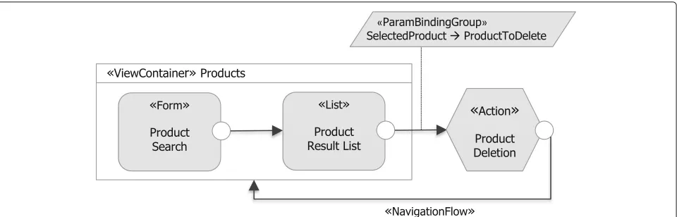
Figure 1 shows a simple example of IFML model, describing a user interface where the user can search for a product by entering some search criteria in the Product Search Form. The model consists of aViewContainer Products(describing a screen or Web page) which con-tains twoViewComponents(visual widgets positioned in the screen), namely theProduct Search Form, where the user can enter the search criteria, and the ProductRe-sultListList, which displays the search results. Further-more, aProduct DeletionActioncan be triggered when the user selects theDeleteEventassociated to Produc-tResultList. This example model conforms to the IFML metamodel, an excerpt of which is shown in Fig. 2.
2.1 Mobile IFML
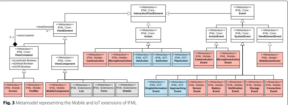
Front-end design is a more complex task in mobile appli-cations due mainly to: (i) the smallness of the screens of mobile devices. This constraint requires an extra effort in interaction design at the purpose of exploiting at the best the limited space available; (ii) Mobile apps interact with other software and hardware features installed on the device they are running on; and (iii) the user interaction which is basically done by performing precise gestures on the screen or by interacting with other sensors. These interactions often depend on the device, the operating system and the application itself. This section presents a mobile extension of IFML designed for expressing the content, user interaction, and control behaviour of the front-end of mobile applications [13]. An excerpt of those extensions, along with the IoT extensions presented in Section 4, is depicted in Fig. 3.
2.1.1 Containers and components
Fig. 1IFML example: product search, listing and deletion. The model consists of aViewContainerProductswhich contains twoViewComponents (Product Searchform andProductResultListlist); andProduct DeletionActiontriggered once the user selects theDeleteEventassociated to
ProductResultList
the mobile context. A new class calledScreenhas been defined to represent the screen of a mobile application. Since the screen is the main container of a mobile appli-cation, it extends the core classViewContainerof the IFML standard. The classToolBarrepresents a partic-ular sub-container of the screen. It may contain other containers and may have on its boundary a list of events. It extends the core classViewContainer of the IFML standard.
The class MobileComponent denotes the particu-lar mobile view component such as button, image, and icon. A MobileComponent is subject to user events, described next.
A characteristic trait of mobile interfaces is the uti-lization of predefined ViewContainers devoted to specific functionalities that are provided at the oper-ating system (including Notifications area and Settings panel). These system level containers provide econ-omy of space and enforce a consistent usage of com-mon features. TheMobileSystemstereotype has been defined to distinguish these specialViewContainers.
A ViewContainer stereotyped as MobileSystem
denotes a fixed region of the interface, managed by mobile operating system or by another interface framework in a cross-application way. TheMobileSystemstereotype can be applied also to AViewComponentsto highlight
Fig. 3Metamodel representing the Mobile and IoT extensions of IFML
that the interface uses the components of the system (as shown in Fig. 5).
2.1.2 Mobile context
The context is a runtime aspect of the system that deter-mines how the user interface should be configured and the content that it may display. The context assumes a particular relevance in mobile applications, which must exploit all the available information to deliver the most efficient interface. Therefore, the context must gather all the dimensions that characterize the user’s intent, the capacity of the access device and of the communication network, and the environment surrounding the user. A new classMobileContextextending theContexthas been defined to express the mobile contextual features.
2.1.3 Events
In this section we describe the new event types that are defined within IFML for the mobile context. A new class MobileUserEvent allowing the model-ing of the mobile user events have been defined.
MobileUserEvent extends ViewElementEvent of
the IFML. TheMobileUserEventis further extended to model the specific mobile user events. Its specific extensions include: DragDrop, DoubleTap, Touch, and LongPress. Each of them represents an event related to the gesture which triggers it.
The screens in Fig. 4a show an example of the usage of theLongPressgesture allowing the user to manage the selected list. Figure 4b shows a fragment of IFML model for lists management. When a user performs the LongPressgesture on one element of the list, a pop up containing information of the selected element is shown allowing her to edit or delete the list.
A new class MobileSystemEvent has been defined to express the mobile system events. It extends SystemEventof the IFML. The following classes extend MobileSystemEventfor specific system events:
• SensorEvent, defining events related to the sensors of the device;
• BatteryEvent, describing the events related to the state of the battery;
• NotificationEvent, grouping the events related to the generic notifications handled by the operating system;
• StorageEvent, describing the events related to the archiving capacity; and
• ConnectionEvent, describing the events related to the connection state of the device.
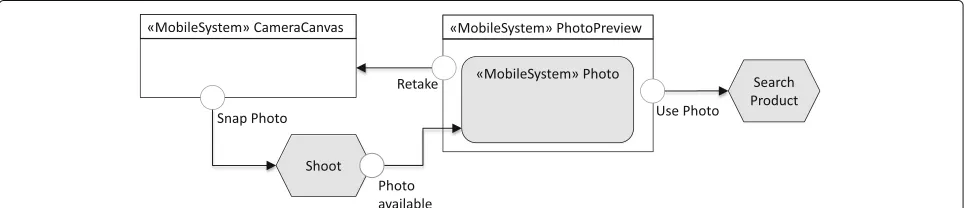
MobileActionEvent class has been defined to model the events triggered by a mobile action. Among mobile actions, we have actions related to the photo camera such as the Shoot action and actions related to microphone. Figure 5 shows example of such events. A user takes a photo with the device’s photo cam-era and the application displays the product corre-sponding to the taken photo if any. Once the photo is available, a screen asking the user if he wants to use or retake the photo is displayed. The photo available CameraActionEvent is associated to the CameraActionshoot.
3 Use cases
In this section we present the main use cases we identi-fied for the IoT applications. Before proceeding with the use case specifications, we provide a quick summary of the IoT terminology used in the paper. In particular, we will make use of the following IoT concepts:
• Device or Thing:It denotes all types of devices which can generate information (about physical event or state) and initiate, modify, or maintain those events or states; or that can perform actions.
a
b
Fig. 4Example ofLongPressevent used to display options of a pressed list:athe user interface representing the performed gesture;bthe corresponding IFML model
• Terminal: A terminal is any device which can run an IoT application with a user interface which can control other devices through the network.
• Communication: The devices can communicate in different ways and can be connected with terminals and external systems. Several communication proto-cols for the IoT have been proposed around the IEEE 802.15.X standard.
• External System: With external system we refer to all the systems connected to a network in which the information of devices and terminals can be stored, processed and retrieved. Examples of the external
systems include enterprise management systems such as customer relationship management (CRM) and enterprise resource planning (ERP).
• Intermediary: It represents any device or system which acts as a gateway between the IoT device and the terminal in an indirect communication.
The use cases we identified for the IoT applications are based on our industrial experiences as well as on an extensive investigation on IoT applications available on the market and what is expected to be the user inter-face of the IoT applications in different areas of their application.
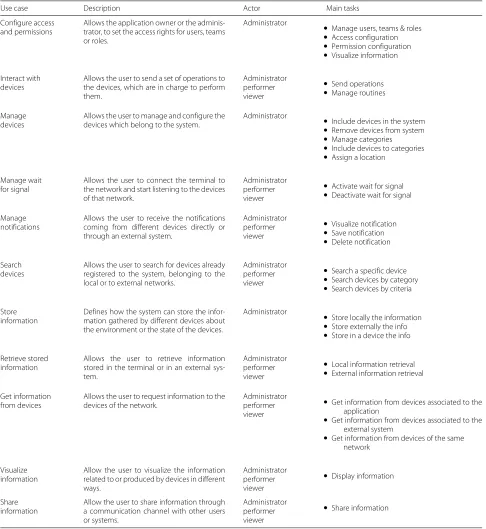
In particular, we rely on direct experience on scenarios in the fields of building monitoring (with sensors and actuators controlling the status of large venues used for public events), smart cities (covering the needs of mon-itoring people flow including pedestrians and vehicles, parking availability and public transportation), market-ing and sales monitormarket-ing (for controllmarket-ing interactions with store windows and artifacts), and massive sensor deploy-ment on commercial goods for adaptive maintenance (large appliances). Furthermore, we investigated the pos-sible uses of IoT equipped products for the consumer market, produced by famous vendors (Philips, bTicino, Vimar, and others). Out of this analysis we derived a set of abstract use cases that cover all these scenarios. We present those use cases using the following schema: for each use case we provide adescription,primary actor, and main tasks. The detailed list of use cases is reported in Table 1.
The user of the IoT application could have differ-ent roles, defined as a set of allowed actions. The main roles are: Administrator, the user who has access rights to the whole system, including the external sys-tems; Performer, the user who can manage and inter-act with the devices of the local network; and Viewer, the user who can display the information of the devices or the information about the environment monitored by those devices. The use cases reported in Table 1 essentially cover device and user management, IoT devices usage, and data management. The identified use cases are: Configure Access and Permission, Manage Devices, Interact with Devices, Manage Wait for Signal, Search Devices, Manage Notifications, Get Information from Devices, Visualize Information, Share Information, Store Information, Retrieve Stored Information. Their detailed characterization reported in Table 1 responds toRQ1.
4 Modeling language for IoT
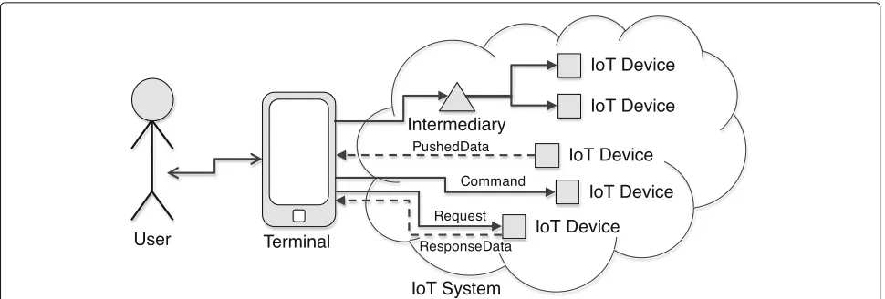
In this section we address the specification of a domain-specific language for IoT UI design, thus responding to RQ2. The interactions between the user and the IoT sys-tems, as shown in Fig. 6, can be logically divided in two phases: (i) UserTerminal communication. This phase represents the interactions between the user and the terminal used to access the IoT system; and (ii) TerminalIoT devicescommunication. This phase rep-resents the interactions between the terminal and the IoT devices. The first phase can be modeled using the IFML standard and its extensions, especially the Mobile IFML (introduced in Section 2.1). This section addresses the second phase of the interactions with the IoT sys-tem. It presents the new elements added to the IFML to model both the events and actions associated to the IoT devices.
4.1 Content model
This section presents the content model of an IoT system. The designed model covers use cases presented in Section 3, with a multi-tenant and enterprise perspective. Indeed, the use cases described so far represent the per-spective of a single IoT system. Based on this, we now aim at a platform that supports multiple IoT systems within and across enterprises. Therefore, the proposed model allows to define a unique infrastructure for a multi-tenant application platform that can serve multiple customers at the same time.
Figure 7 shows a piece of content model. The model comprehends the concepts needed for modeling the application’s users and the structure of an organization and its customers and the concepts needed to define IoT services.
• User, it represents the physical user that access the application. The user can be either aCustomerUser or aOrganizationUserreferring respectively to a cus-tomer or a company.
• Tenant, this concept defines an access domain for either an organization or a customer. The Tenant is characterized by its own configurations and graphi-cal layout. It is the main partitioning condition for the data.
• Organization, it describes a company that offers a ser-vice to the customer. The organization produces and sellsThingsmanaged by the application. The organi-zation belongs to a tenant or another organiorgani-zation. • Customer, this concept describes a company that
either bought or uses service from the organization. The customer has a reference to the organizations that sold theThingsor provides technical assistance. • Branch, it represents a sub organization unit
belong-ing to a customer.
• Location, it represents a physical location owned by a Customer. The location is the place where a Thing is installed (e.g. office, store, and plant).
• Thing, this concept represents a generic object con-nected to Internet, able to send and receive data. The characteristics of a thing are defined by the corre-spondingThingDefinitionand it is bound to a specific Location.
• ThingDefinition, it represents the definition of a Thing. It describes the exposedMetricsand the sup-portedCommand.
• Command, it represents an instruction that can be executed by a Thing. A Command has a name and a set ofCommandParameter characterized by a name and a type.
Table 1IoT use cases
Use case Description Actor Main tasks
Configure access and permissions
Allows the application owner or the adminis-trator, to set the access rights for users, teams or roles.
Administrator
• Manage users, teams & roles
• Access configuration
• Permission configuration
• Visualize information
Interact with devices
Allows the user to send a set of operations to the devices, which are in charge to perform them.
Administrator performer viewer
• Send operations
• Manage routines
Manage devices
Allows the user to manage and configure the devices which belong to the system.
Administrator
• Include devices in the system
• Remove devices from system
• Manage categories
• Include devices to categories
• Assign a location
Manage wait for signal
Allows the user to connect the terminal to the network and start listening to the devices of that network.
Administrator performer viewer
• Activate wait for signal
• Deactivate wait for signal
Manage notifications
Allows the user to receive the notifications coming from different devices directly or through an external system.
Administrator performer viewer
• Visualize notification
• Save notification
• Delete notification
Search devices
Allows the user to search for devices already registered to the system, belonging to the local or to external networks.
Administrator performer viewer
• Search a specific device
• Search devices by category
• Search devices by criteria
Store information
Defines how the system can store the infor-mation gathered by different devices about the environment or the state of the devices.
Administrator
• Store locally the information
• Store externally the info
• Store in a device the info
Retrieve stored information
Allows the user to retrieve information stored in the terminal or in an external sys-tem.
Administrator performer viewer
• Local information retrieval
• External information retrieval
Get information from devices
Allows the user to request information to the devices of the network.
Administrator performer viewer
• Get information from devices associated to the application
• Get information from devices associated to the external system
• Get information from devices of the same network
Visualize information
Allow the user to visualize the information related to or produced by devices in different ways.
Administrator performer viewer
• Display information
Share information
Allow the user to share information through a communication channel with other users or systems.
Administrator performer viewer
• Share information
is characterized by a name, a measurement unit, and a type (e.g. integer, float, and boolean).
• Measure, it represents a value of a metric at a specific timestamp. A set of measures constitute time series. Things send measures to the server runtime system at regular intervals or when particular events occur.
4.2 Interaction model
Fig. 6Overview of the user interaction with the IoT Systems through the terminal, consisting in sending commands and requesting or monitoring data from the IoT devices (possibly through an intermediary)
4.2.1 IoT actions
This category comprehends the components describing the actions triggered when the user interacts with dif-ferent IoT devices. Those actions can be grouped into two categories:Device actions, that represent the actions sent directly to the devices; and Intermediary actions, that represent the actions sent to the devices through an Intermediary(a component that manages the communi-cation between the user and the devices). Each category can be further decomposed into two subcategories: Set and Get actions. Notice that the content model takes care of defining the concepts related to the data transfer,
through MetricandMeasure (which actually contain all the metadata about data transfer formats, size and so on).
Set actions. This category contains the actions which permit the user to send to one or more devices, a series of identifiers of the operations or programs which those devices have to perform or execute. We assume that the operations are known a priori by the devices, thus when we send an identifier of an operation to a given device, the device knows how to perform the corresponding opera-tion. TheSetoperations are mainly used to configure the devices (e.g.: change the range in which the sensors are
activated) and to perform specific actions such as turn onandturn off the device. We have defined a new class, SetAction, that allows the modeling of those actions (see Fig. 3).
Get actions. TheGetactions are mainly used to retrieve the information from devices, category of devices, a pro-gram or an operation. We have defined a new class, GetAc-tion, that allows the modeling of those actions (see Fig. 3). The classGetActionhas been further extended to rep-resent the specific data to retrieve. Examples of those data include details and state of the device, information pro-vided by the device and status of the operation assigned to the device.
Plan actions. For the previous actions, we assume that the devices execute specified operations once the user triggers the action. But there exist other cases in which the user wants to schedule the execution of a given action at a specific time. We have defined a specific action, called PlanAction, to model those operations which are not executed immediately by the devices but sched-uled for execution (once or several times) in a subsequent moment. PlanAction is an asynchronous action that waits until the time scheduled for the execution of the operation. It inputs the targeted devices, execution time, operations, and optionally (for the repeating actions or operations) the number of repetitions.
4.2.2 IoT events
In this section we describe the new events defined as IFML extension for the IoT domain. Those events are grouped in: events from devices, and events associated to IoT actions.
Events from IoT devices. The IoT devices emit specific signals containing information about their status or about what they are monitoring. Those signals are captured by specific catching events and sent to the users (terminal) in form of notifications. Those events are grouped into two categories:
1. Single Information Event. It is an event which captures every single message from the device it is listening to. A new classSingleInformationEvent extend-ing SystemEventof the IFML standard has been defined to model those events.
The usage of this event is exemplified in the Fig. 8. In this example, the information from the device is shown to the user only once the terminal is con-nected. To test the connectivity
we use theActivationExpression, a Boolean condition which determines whether the associ-ated ViewElement is active or inactive, associassoci-ated
to the event. TheActivationExpression Con-text. ConnectivityType<>“NONE” states that the SingleInformationEventwill be activated only when there is a network activated on the terminal. 2. Approaching Event. It is an event allowing to capture
the first signal sent by the device to which is associ-ated. This event is used when the data transmitted by the device must be shown to the user only once, i.e., each time the device is detected for the first time by the terminal.
A new class, ApproachingEvent, extending SystemEvent has been defined to model the approaching events. The usage of this event is exem-plified in Fig. 9. In this example, the information from the device is shown to the user once the user enters in the coverage area of the device transmitting via BLUETOOTH. TheActivationExpression “Context. ConnectivityType = “BLUETOOTH” states that user receives information from the device only when the BLUETOOTH connectivity is activated on his terminal.
Action events. This category groups two types of events: Timer event, denoting the time on which the associ-ated action is scheduled for execution; andRepeat event, specifying the time on which the execution of the asso-ciated action will be repeated. We have defined a new class for each type of those events: TimerEvent and RepeatEvent.
5 Interaction patterns for IoT
In this section, we present the IoT interactions under a problem-oriented view, with the aim of showcasing some exemplary and reusable solutions to typical problems, thus responding toRQ3. We introduce a number of pat-terns that can be used to tackle typical problems in the design of the user interactions (UI) with the aim of show-ing the expressiveness of the designed IoT extensions. We show the matching between those patterns and the user interface patterns defined in the context of IFML [14]. We also present a set of alternative data synchronization patterns which can be relevant to different IoT solutions, and we analyze their compatibility with the UI patterns for IoT.
5.1 IoT patterns
The UI design patterns for the IoT systems can be grouped into three categories: Set Patterns, Get Patterns, and Event-based Patterns.
5.1.1 Set patterns
Fig. 8Example of usage ofSingleInformationEvent. A notification is shown to the user when the event is activated
Figure 10 exemplifies one pattern of this category, One Device One Operation, a pattern which allows the user to set an operation to be executed by one specific device. The user selects a device of interest from a list of the devices of the system. Then, he chooses the operation to be per-formed from a list of operations supported by the selected device.
Other patterns of this category are: • One Device More Operations, • More Devices One Operation, • More Devices More Operations, • One Device One Program, and • One Category More Operations described in Appendix (Table 6).
5.1.2 Get patterns
This category comprehends interaction patterns allowing to retrieve information from a device, category, program or operation. Figure 11 exemplifies one pattern of this cat-egory,Get Details of a Device, a pattern which allows the user to retrieve the general information about the device such as Id, name, description, and model. The user selects a device he is interested in from a list of devices.
Other patterns of this category are: • Get State of the Device,
• Get Information from the Device, • Get Information for One Category, • Search Device, and
• Nearby Devices
described in Appendix (Table 7).
5.1.3 Event-based patterns
This category regroups patterns triggered by an occur-rence of a specific events. Figure 12 exemplifies one pat-tern of this category,Pull Information. This pattern allows the user to check periodically availability of new data from devices. To save some resources like power, for the data that can be delayed for some amount of time without impacting on the outcome of the application, the user can decide to activate periodically the listening service and pull all the information from the devices.
Other patterns of this category areApplication Launch andPush Information, described in Appendix (Table 8).
5.2 User interaction patterns
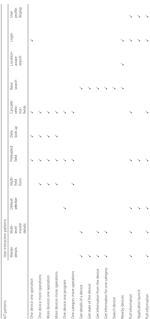
The work on [14] presents a set of design patterns that can be used to address typical issues (related to interface organization, content and navigation) of user interface modeling in general. We report in Table 2 a subset of patterns which are relevant, as building blocks, for the modeling of UI patterns for the IoT systems. Table 3 shows a matching between those UI patterns with the IoT pat-terns introduced in Section 5.1. As rows of Table 3, we list the IoT patterns, while as columns we have generic UI pat-terns. A checked cell (i×j) means that thejth UI pattern has been (can be) used to model theith IoT pattern.
The work on [14] covered also the traditional database operations of creation, update and deletion of an object of a given entity—CRUD Patterns. In the IoT context, those patterns are used to configure an IoT system by adding, updating or removing an IoT object to the repository of
Fig. 10Example of Set Pattern: One Device One Operation
the system. Those patterns are not explicitly considered in this section since they regard the static part of the IoT system.
Permission and Access configuration.Security is a key issue in IoT systems. In Section 3, we have reported the common roles in an IoT system. The configuration of per-mission and access rights is done by using the CRUD pattens on users, groups and by assigning the access rights to the group of users. Access control is then managed by theLoginandUser managementpatterns (see Table 2).
5.3 Data synchronization patterns
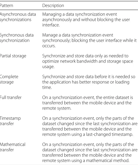
There are several factors to consider when trying building a model to describe data alignment. Data synchronization patterns have been widely studied in computer science. We report the patterns that can be applied in the context of IoT-based applications in Table 4, while a synthesis of the compatibility between those patterns and user inter-action patterns for the IoT-based applications is reported in Table 5. The table lists the user interaction patterns for the IoT-based applications as rows and the data synchro-nization patterns as columns. A checked cell indicates a possible match in the adoption of the corresponding pair of patterns.
6 Example
To demonstrate the effectiveness of the designed exten-sions and usage of UI design patterns presented in
Fig. 11Example of Get Pattern: Get Details of a Device
Section 5, we have modeled the interaction of smart-home, an application that allows a user to interact with different devices of a smart home system. The example is inspired by a real world project implemented by our approach and reported in Section 8.
Figure 13a contains a piece of the user interface of smart-homeapplication. The UI in Fig. 13a is divided in three paths: (i) Manage cameras. When the user selects manage camera from the Home screen, a new screen Camerasshowing a list of available cameras is displayed. The screen shows real-time images from the selected camera. The button Details associated to each camera allows the user to access to the details, state and cur-rent image, of the selected camera; (ii) Manage Lights. Once the user selects Manage Lights from the Home screen, a new screen calledLightsis displayed. The screen Lights, contains a list of available lights with their cur-rent state (ON or OFF). The user can change the state of the selected light by pressing on/of button associ-ated to each light; (iii) Manage Alarms. The path which allows the user to see the logs of recent alarms. Once the user selects manage alarm from the home screen, a new screenRecent Alarmscontaining a list of the recent alarms is displayed.
Figure 13c shows the IFML model describing the user interaction of the piece ofsmart-home application. The interaction model is obtained by combining the following IoT user interaction patterns:
• Get Information from One Category, used to retrieve the current status of the monitored lights;
• Get State of the Device, used to retrieve the current state ofCamera01;
• Get Information from the Device, used to retrieve the information about the object monitored (image displayed on screen ofCamera 01);
• One Device One Operation, used for instance to turn off theLight01;
• Get Details of a Device, used to access the details of the selected logLine of the alarms.
• Store Information, used to store the new alarm; • Push Information, used to inform the user about the
new alarm. In the exemplified case, the new alarm arrived (as a notification message) while the user was visualizing an updated list of Lights after turning off the Light01.
7 Implementation
Fig. 12Example of Event-based Pattern: Pull Information
development of UIs and now building a new offer for IoT3. The platform relies on a single, general-purpose static data model (introduced in Section 4.1) representing any infrastructure for managing IoT systems. Our implemen-tation relied on WebRatio, a development environment supporting IFML that comprises several modeling per-spectives and includes a code generation framework that
Table 2User interaction patterns Pattern Description
Master details and multi-details
Present some items and a selection permits the user to access the details of one instance at a time.
Multi-level master details
Also called cascaded index, consists of a sequence of lists over distinct classes, such that each List specifies a change of focus from one object, selected from the index, to the set of objects related to it via an association role. In the end, a single object is shown.
Default selection Simulates a user’s choice at the initial access of a list, thus selecting a default instance.
Multi-field form Form for submitting information through several fields.
Preloaded field Variant of Multi-field Form where some fields are preloaded with existing values.
Pre-assigned selection field
Form where the value of a selection field is pre-selected.
Data lookup Useful for data entry task that involves a complex form with choices among many options, such as in the case of form filling with large product catalogs.
Cascade selection fields
Useful for data entry task that involves entering a set of selections which have some kind of dependency between each others.
Basic search Keyword search upon a collection of items.
Location-aware search
Enables search of items that are related and close to the current user position.
Login Recognizes and checks for validity a user-provided identity.
User management Shows and enables editing application-dependent information associated with the identity of an authenticated user.
automates the production of the software components in all the tiers of the application and the connection between the application and external APIs.
From architectural perspective, we can see the plat-form as a multitenant stateless server application and a set of thick client applications. Clients maintain the session of authenticated users and are responsible for the com-position of the user graphical interface. No presentation logic is executed on the server. The backend serves data, either in pull or push fashion, and executes the business logic.
7.1 Backend
The back-end architecture is composed by the following components: Microservices layer and API gateway.
7.1.1 Microservices layer
The microservices layer provides access to the data. A microservice is a standalone, independently deployable software system, which provides a specific and atomic functionality. The micro-services present in our archi-tecture include: (i) Identity, which provides information for user management; (ii) Network, which groups the concepts related with the organizational structure of the actors; (iii)Inventory, which groups the concepts related to the definition of things; (iv)Data, which allows clients to access to the actual value gathered by the IoT sen-sors; and (v)View, which allows managing all the graphical resources used by the clients.
7.1.2 API gateway
The API gateway is a component that works as proxy toward the micro-services. It exposes the micro-services APIs to the clients.
7.2 Client architecture
Table 3 Synthesis of User Interaction Patterns used to model IoT Patterns IoT p atterns U ser interaction patterns Master details Multi- level master details Default selection Multi- field form Preloaded field Data look
up
Cascade selec- tion fields Basic search Location- aware search
Table 4Data Synchronization Patterns Pattern Description
Asynchronous data synchronizations
Managing a data synchronization event asynchronously and without blocking the user interface.
Synchronous data synchronization
Manage a data synchronization event
synchronously; blocking the user interface while it occurs.
Partial storage Synchronize and store data only as needed to optimize network bandwidth and storage space usage.
Complete storage
Synchronize and store data before it is needed so the application has better response or loading time.
Full transfer On a synchronization event, the entire dataset is transferred between the mobile device and the remote system.
Timestamp transfer
On a synchronization event, only the parts of the dataset changed since the last synchronization are transferred between the mobile device and the remote system using a last-changed timestamp.
Mathematical transfer
On a synchronization event, only the parts of the dataset changed since the last synchronization are transferred between the mobile device and the remote system using a mathematical method.
with the templates specific forthingsandmetrics, and the graphic elements owned by the correspondenttenant.
Figure 14 shows an example of an interaction between the client and the API Gateway in order to perform a request. Initially the client requests a token by using the /authenticate endpoint. The API Gateway then queries the Identity microservice to verify the client credentials and generate a token. The client saves the token and use it for the subsequent requests. In the exemplified case, the client performs a request to retrieve all the Things belonging to itsCustomer.
Figure 15 reports a piece of the user interface of a Web application implemented for supporting a IoT-based scenario.
8 Experiences and validation
Thanks to the collaboration with the Semioty team of WebRatio, we had the possibility of validating our approach around ten real industrial cases. In this section we report our experience within three of them. They represent significant real-world cases to which we have applied our approach, and thus have been useful for vali-dating our solution too.
8.1 Home automation system
A company specialized in consumer home automa-tion soluautoma-tions needed a mobile applicaautoma-tion for home
automation systems management. The requirements of the application were:
• monitoring of various home appliances: HVAC (heat-ing ventilation and air condition(heat-ing), lights, security system (cameras and alarms), watering system, and environmental sensors;
• visualization of the status of all the appliances and devices, filter devices, and highlight the active ones; • Real time notification about consumption and states
of appliances;
• Multi-platform (iOS, Android, and Windows) and multi-device (Smartphone and Tablet) implementa-tion. In particular, the Tablet version shall allow the visualization of the house map with the things in their respective rooms;
• Remote configuration of the home automation sys-tem, by sending commands to devices like turning on/off the lights. The commands can be sent to a single device or a group of them.
8.2 Smart ovens for bakery industry
A company specialized in manufacturing of ovens for bak-ery industry, needed a tool allowing the configuration and monitoring of industrial ovens deployed on their cus-tomers’ premises. The tool shall provides four different user interfaces:
1. The Production Dashboard for the final user of the oven. It shall visualize information related to the use of the oven. The information to visual-ize include: cooking sequences in temporal order and details (dates and times, completion percent-age, carriage load, calculated energy consumption and temperature profile) of the cooking in progress and made. It shall also allow to send recipes to the oven.
2. TheDashboard for Power Management. It shall visu-alize the information regarding energy consumption of the oven, which include: (i) Current and previ-ous consumption referenced by day, week, month and year; (ii) Calculation of energy consumption costs referring to day, week, month and year; and (iii) Energy consumption and average cost per recipe. For each, the consumption and the average cost of all cooking are displayed.
3. TheDashboard for Maintenancewhich shall allow to visualize and manage the status of various compo-nents of the oven.
4. The Recipe Dashboard shall allow to visualize, edit, add and delete recipes available for the oven.
8.3 Industrial printers management
a
c
b
Fig. 13Example of pattern-based modeling:aa piece of user interface ofsmart-houseapplication;bSmart objects considered insmart-house
application;cThe user interaction model of the application, obtained by combining together various design patterns
monitoring of: (i) the different states assumed by the printer during a given interval of time; (ii) printing parameters (including velocity, number of prints, and quantity of ink); and (iii) overall equipment effectiveness statistics. The final aim of the system is to enable pre-dictive maintenance and continuous monitoring of the
devices, so as to increase the level of service for the customers.
8.4 Preliminary validation
Fig. 14Example of interaction between the client and the server
with satisfaction of the customer. The generated applica-tions consisted in a cloud-based deployment of the server side of the system, plus (when needed) multi-platform mobile apps generated on Cordova PhoneGap distribu-tion. In this stage, since the platform is not yet completely industrialized, due to the diversity of the customers we had to deploy one application per customer, as opposed to the multi-tenant solution devised in our conceptual framework.
Although we didn’t run a comprehensive and detailed validation of the work, we report here the assessment of some quality metrics of our approach.
In terms ofadequacy of the modeling language, we can report high satisfaction of the designers. Indeed the defined content model and user interaction components were completely covering all the requirements of all the applications. The only case that could not be covered completely automatically was the one of the design of the
map of the location with the position of the devices. To optimize the experience, this had to be manually imple-mented in Javascript.
In terms ofexecutability, the generators and execution platform were covering the requirements too: all the gen-eral structure of the application, the navigation and the main contents of the pages have been generated automat-ically. The part of interfaces that could not be generated is basically the customization of the user interface style.
In terms of coverage of the design patterns, all the main behaviour could be covered and were subsumed by one or another pattern. Therefore the design of the basic application structure could be specified with a pattern-based approach. What could not be covered with this was the connection between patterns: this part required some manual design and refinement of the models for opti-mizing the experience in the move from a use case (i.e., pattern) to another.
9 Related work
This work is related to a large corpus of researches that apply model-driven development (MDD) to specify the user interaction for multi-device UI modeling. Among them we can cite: UsiXML [15], TERESA [16], IFML [12], and MARIA [17]. These approaches deal with the specifi-cation of general purpose user interfaces and interaction and they are agnostic with respect to the technical plat-form or technology. Our approach instead focuses on the specifics of user interactions for IoT systems.
On the other side, the approaches that apply MDD to the development of IoT-based applications do not specifically focus on user interfaces; they can be grouped into two clusters.
The first cluster includes the works that target exe-cutability for IoT, i.e., produce executable code for the IoT-based applications. Among them we can cite: (i) FRASAD (Framework for sensor application develop-ment) [18], a node-centric, multi-layered software archi-tecture which aims at filling the gap between applications and low-level systems of sensor nodes. It provides a rule-based programming model which allows to describe the local behaviors of the sensor node and adomain specific language for sensor-based applications modeling. The final application code is automatically generated from the initial models; (ii) Pankesh Patel and Damien Cassou [19] proposed a development methodology which consists on separating the IoT application development into different concerns: domain, functional, deployment, and platform. This separation allows stakeholders to deal with those concerns individually and reuse them. The framework integrates a set of modeling languages to specify each of which allowing to describe one of the above mentioned concerns of the IoT applications; (iii) Franck Fleurey et al. [20] proposed a MDD approach to generate efficient com-munication APIs to exchange messages with and between resource-constrained devices. This approach is based on ThingML (things modeling language) [21]; (iv) Mainetti et al. [22] proposed a conceptual model for IoT, the Web of Topics (WoX). WoX extends the concept of topic from the MQ Telemetry Transport (MQTT) publish-subscribe protocol [23] with the aim of filling the gap between the design and the solution domains in the IoT context. In WoX the generic IoT entity is seen as a set of couples Topic-Role. A WoX Role is expressed in terms of tech-nological and collaborative dimensions; (v) Conzon et al. [24, 25] provided a model driven development toolkit based on the semantic discovery service, allowing to dynamically selecting and locating available resources or devices, and provides a graphical interface allowing devel-opers to compose mashup applications. (vi) Ferry Pramu-dianto et al. [26] proposed a MDD approach which focuses on the separation of domain modeling from techno-logical implementations. The framework allows domain
experts to construct domain models by composing vir-tual objects and linking them to the implementation technologies. It allows automatic generation of a proto-type code from the domain models and manual refine-ment of it. All these approaches have in common the main target, that is executability of IoT systems, while they differ on the development phases covered and the kind of support provided to the designer. In this sense, their main focus is to build APIs or middleware lay-ers so as to mask access to divlay-erse IoT devices, thus allowing discovery, integration and execution of device functions. Our work is targeting an orthogonal dimen-sion, that is user interaction. As such, our approach could be used together with one of the approaches discussed above. They can provide the common access layer to the devices, and our solution can provide model-driven specification and execution of the application layer over them.
In the second cluster of MDD approaches we include works that applyMDD to other aspects of IoT applica-tions. Among them we can mention a MDD approach for the analysis of IoT applications via simulation [27]. Pre-hofer and Chiarabini [28] compared themodel-basedand mashup approaches, considering tools and methodologies for the development of IoT applications, using UML and Paraimpu [29]. Again, our approach is working on orthog-onal aspects with respect to these issues. However, it can integrate very well with them, thanks to the availability of formal semantics of IFML and of simulation solutions based on IFML [30]. Neither detailed formal specifica-tion nor simulaspecifica-tion/validaspecifica-tion tooling are needed for the proposed extensions for IoT, because we rely on existing resources and infrastructure about IFML. Viceversa, in our approach we concentrate on providing efficient design methods and executability.
10 Conclusions
Appendix
Table 6IoT User Interaction Patterns: Set Patterns
ID Pattern Description Example
P1 One device one operation
This pattern allows the user to set an operation to be exe-cuted by one specific device. The user selects a device of interest from a list of the devices of the system. Then, he chooses the operation to be performed from a list of operations supported by the selected device.
P2 One device more operations
This pattern allows the user to send to a single device a set of the operations to be performed. The interactions start with the selection of a device of interest. Then the user selects desired operations from a list of supported operations.
P3 More devices one operation
This pattern allows the user to send to many devices one operation to be executed. The interactions start by selecting the devices of interest. Then the user selects an operation (from a list of the operations supported by the selected devices) to be executed by those devices.
P4 More devices more operations
This pattern allows the user to send a set of operations to different devices. Those operations are not necessary the same for all devices, thus the operations must be binded to the devices which can perform them.
P5 One device one program
This pattern allows the user to send the program (iden-tifier) to the device which will execute it. Aprogramis a set of operations which have to be executed in a precise order. We assume that the programs are already config-ured in the devices, thus, the user has only to send the program identifier to the device.
P6 One category more operations
This pattern allows the user to set operations to differ-ent devices based on the groups they belong to, without needing to select one device at a time.
Table 7IoT User Interaction Patterns: Get Patterns
ID Pattern Description Example
P7 Get details of a device The user retrieves, the general information about the device such as Id, name, description, and model. The user selects a device he is interested in from a list of devices.
Table 7IoT User Interaction Patterns: Get Patterns (Continued)
ID Pattern Description Example
P9 Get information from the device
This pattern allows the user to retrieve the information provided by a device about the monitored object. The interactions start with the selection of the device for which the user needs tho know the information of the monitored object. Then, the requested information is displayed to the user.
P10 Get Information for one category
This pattern allows the user to get the information from all devices of the same category.
P11 Search device This pattern allows the user to search a specific device. The search of the device can be done in different ways depending on the application and on the devices.
P12 Nearby devices This pattern allows the user to retrieve all the devices near to a given location. The location can be setted by the user or retrieved from the ContextDimension, Position, which represents the location information of the device used to access the application.
Table 8IoT User Interaction Patterns: Event-based Patterns
ID Pattern Description Example
P13 Pull information This pattern allows the user to check periodically availability of new data from devices. To save some resources like power, for the data that can be delayed for some amount of time without impacting on the outcome of the application, the user can decide to activate periodically the listening service and pull all the information from the devices.
P14 Application launch This pattern allows the user to retrieve the information sent by the devices when the application was not running or when he was offline. The launching event calls the external system and gets the notifications sent by all the devices when the user was offline.
P15 Push information This pattern allows the user to visualize the messages sent by an IoT device as a push notification.
Endnotes
1http://www.iiconsortium.org/
2http://www.webratio.com
3http://www.semioty.com
Authors’ contributions
Equal contribution. All authors read and approved the final manuscript.
Competing interests
The authors declare that they have no competing interests.
Publisher’s Note
Springer Nature remains neutral with regard to jurisdictional claims in published maps and institutional affiliations.
Author details
1Politecnico di Milano. Dipartimento di Elettronica, Informazione e Bioingegneria, Piazza L. Da Vinci 32, 20133 Milan, Italy.2WebRatio s.r.l, Piazzale Cadorna, 10, 20123 Milan, Italy.
References
1. Koreshoff TL, Robertson T, Leong TW (2013) Internet of things: a review of literature and products. In: Proceedings of the 25th Australian
Computer-Human Interaction Conference: Augmentation, Application, Innovation, Collaboration. OzCHI ’13. ACM, New York. pp 335–44. doi:10.1145/2541016.2541048
2. Vatsa VR, Singh G (2015) A literature review on internet of things (iot). Int J Comput Syst (ISSN: 2394-1065) 2(08)
3. Atzori L, Iera A, Morabito G (2010) The internet of things: A survey. Comput Netw 54(15):2787–805. doi:10.1016/j.comnet.2010.05.010 4. Broll G, Rukzio E, Paolucci M, Wagner M, Schmidt A, Hussmann H (2009)
Perci: Pervasive service interaction with the internet of things. IEEE Internet Comput 13(6):74–81
5. Kranz M, Holleis P, Schmidt A (2010) Embedded interaction: Interacting with the internet of things. IEEE Internet Comput 14(2):46–53
6. Shirehjini AAN, Semsar A (2017) Human interaction with IoT-based smart environments. Multimed Tools Appl 76(11):13343–65
7. Da Xu L, He W, Li S (2014) Internet of things in industries: A survey. IEEE Trans Ind Inf 10(4):2233–243
8. Capello F, Toja M, Trapani N (2016) A real-time monitoring service based on industrial internet of things to manage agrifood logistics.
In: Proceedings of the 6th International Conference on Information Systems, Logistics and Supply Chain, Bordeaux, France, Available From: http://ils2016conference.com/wpcontent/uploads/2015/03/ ILS2016_FB01_1.Pdf, Accessed. pp 10–21
9. Holler J (2014) From Machine-to-machine to the Internet of Things: Introduction to a New Age of Intelligence. Academic Press, Amsterdam. ISBN:978-0124076846
10. Vermesan O (2014) Internet of things - from research and innovation to market deployment. River Publishers, Aalborg. ISBN:9788793102941 11. Farooq M, Waseem M, Mazhar S, Khairi A, Kamal T (2015) A review on
internet of things (iot). Int J Comput Appl 113(1):1–7
12. Brambilla M, Fraternali P, et al. (2014) The Interaction Flow Modeling Language (IFML), Version 1.0. Technical report, Object Management Group (OMG), http://www.ifml.org
13. Brambilla M, Mauri A, Umuhoza E (2014) Extending the Interaction Flow Modeling Language (IFML) for Model Driven Development of Mobile Applications Front End. In: Awan I, Younas M, Franch X, Quer C (eds). Mobile Web Information Systems: 11th International Conference, MobiWIS 2014. Proceedings. Springer International Publishing, Cham. pp 176–91. doi:10.1007/978-3-319-10359-4_15
14. Brambilla M, Fraternali P (2014) Interaction Flow Modeling Language: Model-Driven UI Engineering of Web and Mobile Apps with IFML. Morgan Kaufmann Publishers Inc., USA
15. Vanderdonckt J (2005) A MDA-compliant environment for developing user interfaces of information systems. In: Pastor O, Falcão e Cunha J (eds). Advanced Information Systems Engineering: 17th International Conference, CAiSE 2005. Proceedings. Springer Berlin Heidelberg, Berlin. pp 16–31. doi:10.1007/11431855_2
16. Berti S, Correani F, Mori G, Paternò F, Santoro C (2004) Teresa: a transformation-based environment for designing and developing multi-device interfaces. In: CHI ’04 Extended Abstracts on Human Factors in Computing Systems, CHI EA ’04. ACM, New York. pp 793–4.
doi:10.1145/985921.985939
17. Paternò F, Santoro C, Spano LD (2009) Maria: A universal, declarative, multiple abstraction-level language for service-oriented applications in ubiquitous environments. ACM Trans Comput-Hum Interact 16(4):19:1–19:30. doi:10.1145/1614390.1614394
18. Nguyen XT, Tran HT, Baraki H, Geihs K (2015) Frasad: A framework for model-driven iot application development. In: 2015 IEEE 2nd World Forum on Internet of Things (WF-IoT). IEEE. pp 387–92.
doi:10.1109/WF-IoT.2015.7389085
19. Patel P, Cassou D (2015) Enabling high-level application development for the internet of things. J Syst Softw 103:62–84
20. Fleurey F, Morin B, Solberg A, Barais O (2011) Mde to manage communications with and between resource-constrained systems. In: MODELS. Springer, Berlin. pp 349–63
21. Fleurey F, Morin B (2016) ThingML. http://thingml.org. Online; Accessed 6 Sept 2016
22. Mainetti L, Manco L, Patrono L, Sergi I, Vergallo R (2015) Web of topics: An iot-aware model-driven designing approach. In: 2nd IEEE World Forum
on Internet of Things, WF-IoT 2015. IEEE, Milan. pp 46–51. doi:10.1109/WF-IoT.2015.7389025
23. Locke D (2016) MQ Telemetry Transport (MQTT) V3.1 Protocol Specification. https://www.ibm.com/developerworks/library/ws-mqtt/. Online. Accessed 6 Sept 2016
24. Conzon D, Brizzi P, Kasinathan P, Pastrone C, Pramudianto F, Cultrona P (2015) Industrial application development exploiting iot vision and model driven programming. In: Intelligence in Next Generation Networks (ICIN), 2015 18th International Conference On. IEEE. pp 168–75
25. (2016) Ebbits. http://www.ebbits-project.eu/news.php. Online. Accessed 6 Sept 2016
26. Pramudianto F, Indra IR, Jarke M (2013) Model driven development for internet of things application prototyping. In: The 25th International Conference on Software Engineering and Knowledge Engineering, Boston, MA, USA, June 27-29, 2013. pp 703–8.
http://dblp.uni-trier.de/rec/bib/conf/seke/PramudiantoIJ13 27. Brumbulli M, Gaudin E (2016) Towards model-driven simulation of the
internet of things. In: Complex Systems Design & Management Asia. Springer, Berlin. pp 17–29
28. Prehofer C, Chiarabini L (2015) From internet of things mashups to model-based development. In: Proceedings of the 2015 IEEE 39th Annual Computer Software and Applications Conference - Volume 03, COMPSAC ’15. IEEE Computer Society, Washington. pp 499–504. doi:10.1109/COMPSAC.2015.263
29. Pintus A, Carboni D, Piras A (2012) Paraimpu: a platform for a social web of things. In: Proceedings of the 21st international conference on world wide web, WWW ’12 Companion. ACM, New York. pp 401–4. doi:10.1145/2187980.2188059