e
-ISSN: 2278-067X,
p
-ISSN: 2278-800X, www.ijerd.com
Volume 6, Issue 10 (April 2013), PP. 54-59
Real Time Controlling and Testing In an Embedded
Processor under a Multitasking Environment
M.Shankar
1, B.Lalitha
2, Akhil C
3.V, Nijin Karthik
4. C, Praveen
5T.T, A. Sasi
kumar
6Department of Electrical and Electronics Engineering
1,2,3,4,5Sasurie College of Engineering, Vijayamangalam, Tamil Nadu, India
Abstract:- In this paper, we present an embedded platform for real-time controlling and testing of a single phase induction motor in an embedded processor under a multitasking environment. In this project we introduce the concept of ARM 9 processor for controlling the speed and simultaneously measuring the single phase motor parameters such as voltage, current, power, torque, speed etc. These tasks are managed by an operating system Linux 2.6.29.6. The load test and other tests are done by virtual arrangements and the test data are serially transmitted to lab view platform then analyzed and results are displayed in the same environment. The paper explores methods to improve the accuracy of the speed control and reduce the time taken for testing and also improving the reliability of testing.
Keywords:- ARM920T processor, PWM circuit, Single phase squirrel cage induction motor.
I.
INTRODUCTION
Real-time emulation enables confined trailing in the laboratory as well as in the industrial environment,
if tests in the settings are not realizable. The whole system under normal and fault conditions can be realized using real-time emulation tools. Here we introduce an ARM9 based system to control and test the parameters of an electrical machine under a multitasking environment. Controlling and testing are two independent real time operations. Thus this complexity calls for not only fast and powerful computations but also efficient and critical management of the multiple tasks. The main elements of the system include the electrical machine to be controlled and tested, the operating system, scheduling methods for management of tasks and code optimization for achieving performance. For analysis purpose, the paper uses the Samsung S3C2440 Processor based on ARM9 architecture and a single phase squirrel cage induction motor to be implemented in the system. The reasons for selecting this processor are due to its capability to run an Operating System. The Linux based ARM system helps to achieve the real time deadlines more precisely to meet the multi-tasking requirements.
II.
PROPOSED MODEL
III.
SYSTEM DESCRIPTION
Fig 1: Block Diagram of the entire system
The block diagram of the system is shown in the Fig 1. This system is used to design an embedded system for controlling and testing of single phase induction motor. Here we are using the following components 1. Potential Transformer
2. Current Transformer
3. Speed sensor (Proximity Sensor) 4. PWM circuit
5. ARM9 processor
POTENTIAL TRANSFORMER: This circuit is considered to supervise the supply voltage. The supply
voltage is step down by a 0-6v potential transformer. This step down voltage is rectified by the precision rectifier. The precision rectifier is an arrangement obtained with an operational amplifier to have circuit acting like a rectifier. Finally, this circuit provides the dc output voltage of level equivalent to the input voltage to the microcontroller
CURRENT TRANSFORMER: This circuit is considered to supervise the supply current. The supply current is step down by a current transformer. This step down current is transformed to the voltage signal using a shunt resistor. Then this converted voltage signal is rectified with the help of precision rectifier as used in the voltage measurement. The input current equivalent voltage is then served to microcontroller.
PROXIMITY SENSOR: The wheel type metal rod is fixed in the motor shaft. The proximity sensor is placed near the shaft. When the shaft is rotating, the metal rod is crossed the proximity sensors sequentially. So the sensor gives the pulse to the microcontroller. Now the microcontroller counts the pulse. By using this pulse count we can find revolution per minute which is equal to speed of the microcontroller
PWM CIRCUIT: It is a widely used controlling technique in application such as electric motor drives. The average value of voltage (and current) fed to the load is controlled by turning the switch between supply and load ON and OFF at a fast pace. The longer the switch is on compare to off periods a higher the power supplied to the load. The switching frequency can be high because not using the mechanical switching relays. It can be regulated by use of electric filters and be smooth to require analog filter
MICROCONTROLLER: The device is a low power application processor based on ARM920T. The ARM920T provides a high performance for open system requiring full virtual memory management and sophisticated memory protection. This also provides high performance processor solution gives considerable savings in chip.
IV.
HARDWARE DESCRIPTION
The power supply unit consists of step down transformer, bridge rectifier, filter and voltage regulator. The ac voltage, typically 220V rms, is connected to a transformer, which steps that ac voltage down to the level of the desired dc output. A diode rectifier then provides a full-wave rectified voltage that is initially filtered by a simple capacitor filter to produce a dc voltage. A regulator circuit removes the ripples presented in the filtered dc voltage and also remains the same dc value even if the input dc voltage varies, or the load connected to the output dc voltage changes. The two regulators IC 7805 and 7812 are used to get 5V and 12V output. The 5V is used for the microcontroller unit and the 12V for the MOSFET driver circuit.
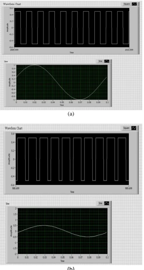
microcontroller checks the speed count value with a required speed reference and the corresponding PWM signals will be produced by the controller and it controls the duty period of the inverter to control the voltage to the single phase induction motor there by controlling the speed of the motor. If any violation occurs in the speed of the motor then the pulse count also gets changed and it is fed backed, compared and controlled accordingly. The real time PWM waves generated during the speed control at various time instant is shown in Fig 2 (a) and (b). Fig 2.a shows the PWM signals generated during the normal period and Fig 2.b shows the PWM signals applied during the speed variations.
(a)
(b)
Fig 2 (a) and (b):Real-time PWM outputs to the Voltage Source Inverter to switch the MOSFET’s for motor speed control at various time instants.
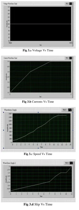
Fig 3.a Voltage Vs Time
Fig 3.b Currents Vs Time
Fig 3.c Speed Vs Time
V.
SOFTWARE DESCRIPTION
A. Linux
A real-time system is one in which the correctness of the system depends not only on performing a desired function but also on meeting a set of associated timing constraints. So the application needs an Operating System (OS) to accomplish multiple tasks in a system. This management is realized by its scheduler based on its scheduling strategies and constraints. When multiple units are involved in a system, especially when they are self-governing, more problems such as resource sharing, data memory deadlock conditions need to be considered. The paper provides a solution to this by building tasks for different modules and using the OS topographies such as semaphores and mutexes. These are used along with a powerful scheduler, which helps in allocating the available resources to the various independent tasks. The execution priority and context switch depends on the OS scheduler and is non-deterministic on a non-real-time kernel. The Linux 2.6.29.6 is used as the OS and it is able to manage multiple tasks based on available scheduler. That’s why we have chosen Linux 2.6.x kernels as a primary OS due to its real-time capabilities.
B. Ni Lab view
NI Lab VIEW programs are generally termed as virtual instruments, or VIs, because their appearance and action duplicate physical instruments, such as oscilloscopes and multimeters. LABVIEW contains a broad range of tools for acquiring, analysing, displaying, and storing data, as well as tools to help troubleshoot the written codes. Various circuits and devices can be interfaced to LabVIEW for analysis and other similar purposes. In our project we us the COM0 serial communication port of the micro2440 board to serially communicate to the LabVIEW environment over a RS 232 protocol. This is a one way communication in which the measurements are transmitted to the LabVIEW. When the kit is interfaced then it detects COM0 port and the communication is established. Various tests including the load test can also be performed in this. While performing load test the virtual arrangement help to vary the load applied over the motor brake drum virtually. Based on these measured and calculated values the waveforms are plotted. The build in waveform blocks can be used to plot the various factors against time. Thus LabVIEW provides correct tools to realize the entire system in real time than any other software.
VI.
CONCLUSION
This proposed model of real time testing and controlling of an embedded processor is mainly used in the industrial and lab areas. The main advantage of our model is used in the multitasking environment. The output of the proposed model is testing and controlling single phase squirrel cage induction motor on a single processor and display various factors like current, voltage, power, efficiency etc. Here we are using ARM920T embedded processor to control the induction motor. Simulation result is shown using Lab VIEW software which will interface with processor kit and display the various parameters mention above and show their waveforms on the display screen.
VII.
REFERANCES
[1]. Y. Rao and M. Chandorkar, “Rapid prototyping tool for electrical load emulation using power electronic converters,” in Industrial Electronics Applications, 2009. ISIEA 2009. IEEE Symposium on, vol. 1, 4-6 2009,pp. 106–111.
[2]. A. Calderon and N. Castillo. (2007) Why arm’seabi matters Online].Available:
http://www.linuxfordevices.com/c/a/Linux-For Services-Articles/Why-ARMs-EABI-matters
[4]. R. Berger. (2010) Embedded gnu/ Linux and real-time an executive summary. Internet draft. [Online]. Available:http://www.reliableembeddedsystems.com/pdfs/2010 03 04 rt linux.pdf
[5]. G. Zhang, L. Chen, and A. Yao, “Study and comparison of the rthal basedand adeos-based rtai
real-time solutions for linux,” Computer and Computational Sciences, International Multi-Symposiums on, vol. 2, pp.771–775, 2006.
[6]. N. Vun, H. Hor, and J. Chao, “Real-time enhancements for embedded linux,” Parallel and Distributed