Location Aided Hybrid Routing Algorithm for
MANET
Mamoun Hussein Mamoun
Faculty of Computer and Information Sciences Mansoura University, Egypt
Abstract-- In this paper, we propose a new hybrid routing protocol for MANET called Location Aided Hybrid Routing Protocol for MANET (LAHRP). The proposed routing algorithm not only aims to optimize bandwidth usage of MANETs by reducing the routing overload but also extend battery life of the mobile devices by reducing the required number of operations for route determination. Although in the LAHRP, some features of both table- driven and on-demand algorithms were used to achieve these goals at some stages, LAHRP algorithm is a completely different approach in terms of position information usage and GPS .
S imulation results are used to draw conclusions regarding to the proposed routing algorithm and compared it with the standard DS R protocol. Conducted experiments showed that our proposed algorithm exhibits superior performance with respect to reactive DS R routing algorithm in terms of normalized routing load, packet delivery ratio and end-to-end packet delay.
Index Term
--
MANET, DS R, New routing protocol forMANET
1. INT RODUCT ION
Wireless networks emerged in the 1970’s, since then they have became increasingly popular. The reason of their popularity is that they provide access to information regardless of the geographical location of the user. They can be classified into two categories: infrastructure and infrastructureless networks. Infrastructure wireless networks, also known as cellular networks, have permanent base stations which are connected to other base stations through links. Mobile nodes communicate with another one through these base stations. Infrastructureless wireless networks, also known as ad hoc wireless networks, are a collection of wireless nodes that does not have any predefined.
Infrastructure or centralized control such as base stations or access points [1].
Ad hoc wireless networks are different from other networks because of following characteristics: absence of centralized control, each node has wireless interface, nodes can move
freely which results in frequent changes in network topology, and nodes have res tricted amount of resources and lack of symmetrical links.
In wired networks, shortest path is usually obtained with distance vector or link state routing protocols. These protocols do not perform well in ad hoc wireless networks because wireless networks have limited bandwidth and there is not central control. Therefore, modifications to these routing protocols or entirely new routing protocols are required for the ad hoc wireless networks [1, 2 and 3]. Table-driven, on-demand and hybrid routing protocols are three main categories of routing protocols for ad hoc wireless networks :
-Table driven routing algorithms:Destination Sequenced Distance Vector (DSDV) [2], Clustered Gateway Switch Routing (CGSR) [3], Wireless Routing Protocol (WRP) [4].
Table driven routing algorithms are also called proactive algorithms. Protocols that use this algorithm find all paths between source-destination pairs in a network and form the newest path with periodic route updates. Update messages are sent even if there are no topological changes. The protocols which are in this category are developed by changing distance vector and link state algorithms. These protocols store routing information in routing tables and give result very slowly because of periodic update of tables. This working strategy is not very suitable for wireless ad hoc networks because of a great deal of routing overload [2].
-On demand routing algorithms: Dynamic Source Routing (DSR)[4], On-Demand Distance Vector Routing (AODV) [5], Temporally Ordered Routing Algorithm (TORA) [2], Zone Routing Protocol (ZRP) [6]
Unlike table driven algorithms, on demand routing algorithms do not form route information among nodes. Routes are founded only in case of necessity. Routes are formed only when needed, in other words when any of the nodes wants to send a packet. Therefore, routing overload is less than table driven algorithms. However, packet delivery fraction is low because every node does not keep updated route information.
DSR algorithm does not send periodic updates. However, there is routing overload because all route information is added into each data packet. This overload increases in state of mobility and traffic density.
-Hybrid routing algorithms: Multi Point Relaying (MPR) based algorithms [7], Position based algorithms: Directional routing algorithm (DIR), most forward within radius (MFR), geographic distance routing (GEDIR) [8], distance routing effect algorithm for mobility (DREAM) [9], Voronoi-GEDIR (V-GEDIR) [10].
Hybrid routing algorithms aim to use advantages of table driven and on demand algorithms and minimize their disadvantages. Position based routing algorithms that is classified in the hybrid routing algorithms category include the properties of table driven and on demand protocols and are usually interested in localized nodes. Localization is realized by GPS that is used to determine geographical positions of nodes. Position changes which occur because of nodes mobility in MANET cause changes in routing tables of nodes. The GPSs, which are embedded in nodes, are used to update information in tables in based algorithms. That makes position-based algorithms different from the table driven and on demand algorithms.
The GPSs have become preferred systems as they provide latitude, longitude and height values at high reliability and low cost. Some of the GPS based hybrid routing algorithms are: directional routing algorithm (DIR), most forward within radius (MFR), geographic distance routing (GEDIR) and distance routing effect algorithm for mobility (DREAM).
Geographic distance routing (GEDIR) algorithm uses geographical information of neighbor and destination nodes in order to determine message packet receivers. The meaning of the neighbor node is the closest node to target node. Algorithm determines the target within a few CPU cycles [11]. GEDIR algorithm use only latitude and longitude parts of geographical information of whole nodes. Every node knows geographical positions of only its own neighbors. Sender knows the location of target node at the same time. When node A wants to send message m to node D, it uses location information of D and location information of the closest one to D among which are 1-hop neighbors.
Distance routing effect algorithm for mobility (DREAM), one of the improved algorithms based on node position information, was suggested in [9]. According to DREAM, the position information obtained by GPS of whole nodes in the network is stored in every node’s routing table. This algorithm is a table driven algorithm since it holds information belonging to whole nodes. According to the algorithm, while node A is sending m message to node B, it uses its position information in order to determine B’s direction. Then it sends m message to 1- hop neighbour on B direction. Each neighbou r repeats the same process. This process continues until message arrives to B (if possible). It resembles on demand algorithms in this respect.
The V-GEDIR is another of the position-based algorithm [10]. In this method, the intersection nodes are determin ed with destination’s possible circular or rectangular voronoi diagram. Another position-based algorithm suggests reducing number of route demander transmitter nodes [12]. The algorithm called Location Aided Routing (LAR) algorithm handles route finding by reducing the search area [13].
GEDIR, MFR, DIR and DREAM calculate internodal position information (latitude and longitude) to decide routing. In this paper, LAHRP has been proposed.
This paper is structured as follows: We investigate the proposed routing protocol (LAHRP) in section 2. Section 3 elaborates on the simulation environment and the experimental results. In Section 4, we present our conclusion.
2. LOCAT ION AIDED HYBRID ROUT ING
The proposed method not only aims to efficiently use the bandwidth by reducing the routing overhead but also battery life is efficiently used by reducing the amount of data to be held and the number of operations to be done for routing by any node in network. In order to achieve above goals, the principles of both on demand and table driven algorithms have been utilized. Nevertheless, the proposed method is entirely different from them. The working principle of infrastructure wireless networks is also benefited in the proposal. As known, there is a central node or station in infrastructure wireless networks, and it is stationary. The nodes in coverage of this station take the information for routing from that and also realized the operation of sending and receiving process through this station.
However, procedures in infrastructure wireless networks have not been used in ad hoc networks up to now since there is not a central node in ad hoc networks or in other words, all nodes are mobile.
In the proposed algorithm, a central node, in other word a master node is assigned as it is in infrastructure wireless networks and directs the routing information. When nodes require sending data to a target node, they take the location of target node and the route to achieve it from master node. Accordingly, they send their data through that route. At this stage, the proposed algorithm differs from infrastructure wireless networks since data is sent via central station in infrastructure wireless networks. However in proposed algorithm, master node, behaving as if it is central node, help only while finding the route to achieve the target
2.1. The Proposed Routing Steps
The proposed algorithm consists of following steps: a. The first node standing up is called as a master node. b. The master node advertises itself as a master node in network by periodically sending broadcast packet.
d. Master node establishes position matrix P using the update messages.
e. Master node firstly calculates distances between every node and others by using position information and then its forms the distance matrix M.
f. Master node calculates the column matrix T. The number of row that has smallest element of T matrix is equal to the number of the node that is in the center of the network. Thus, it is assigned to be candidate master node.
g. Master node asks the candidate master node if it can be the new master node. If the answer is positive, it sends the hole routing information that is keeps on it to the new master node and also it declares new master node and its position to the other nodes. If the answer is negative, the second central node for the T matrix is the new master candidate. The same processes are realized for this node.
h. The new master node sends an advertising packet to network.
i. Other nodes send their update messages to new master node if necessary.
j. Master node determines cost value of each node to other by using fuzzy logic on M and P matrix.
k. An optimization is performed in order to resolve the minimum cost between sources and targets.
l. Nodes ask the master node for the shortest path by sending a route request packet when they want to send data to other node. The master node responds the node asking for the shortest path according to its optimization results.
m. If master node goes far from central position or battery life falls down a threshold, it transfers the mastership to other node, which has minimum row total value in M.
n. Other nodes in network hold in memory only identity and position of master node.
2.2. Explanation of Algorithm
If two nodes stand at the same time in the network, the one which has a smaller MAC address is assigned as the master node. Besides, if the master node closes with any other reason, in order not to lose the routing information, a secondary master should be assigned. The node which is the closest to the master node is chosen as a secondary master. Nodes in networks send update messages to master node so that established position matrix P, which was given in section 2.1 (item d). Information related to any nodes is hold a row of P matrix, where xi, yi, zi are
position data, bi is battery life, di is density and idi is order
number of packet update. The row number of matrix P is equal to number of nodes in network. For a network with k nodes, the matrix is as follows:
P =
k k k k kk
y
z
b
d
id
x
id
d
b
z
y
x
id
d
b
z
y
x
.
.
.
.
.
.
.
.
.
.
.
.
2 2 2 2 2 2 1 1 1 1 1 1 (1)The master nodes calculates distance of each node to other by using the data given in first, second and third matrix P in order to establish the distance matrix M given in section 2.1 (item e). The distances are calculated by the following equation
2
2
2j i j i j i
ij
x
x
y
y
z
z
l
(2)Every item of matrix M is calculated by equation (2) and dimensions of M: row and column numbers are equal to number of nodes in network. For a network with k nodes the distance matrix will be as follows:
M =
k k k k k k kl
l
l
l
l
l
l
l
l
l
l
l
, 3 , 2 , 1 , , 2 3 , 2 2 , 2 1 , 2 , 1 3 , 1 2 , 1 1 , 1.
.
.
.
.
.
.
.
.
.
.
.
.
.
.
.
.
.
(3)The diagonal of M will be zero as the distance of every node
to itself is zero. Also with a condition i ≠ j, the distance between i and j
and the distance between j and i are the same, thus the matrix M will be symmetrical matrix. Therefore the upper triangular part of matrix M will only be calculated. The lower triangular part of M will be filled by upper triangle. As a result of this, the computational time, which is an important factor for battery life of a node, is reduced.
A row matrix T is created by using the total of rows or columns of matrix M given in equation (3) so that the node, which is in the center of network, could be found. The column number of matrix T, which has minimum value, gives the number of node which is in the center of network [10]. For a network with k nodes, the T matrix will be as follows:
T
t
1t
2t
3.
t
k
(4)Where
k n n il
t
1 1According to item i given section 2.1, the nodes in network send their event based update packet to master nodes when there is position change, and when the battery life downs lower than a threshold and processing load increases. The master node clears knowledge related to node and rewrites the knowledge by means of id value transmitted in update packet. Because nodes transmit a value of id in every update packet, which is higher than the value sent in previous packet. Nodes in a network and distances between nodes shown in directed and weighted graph as vertex edges, respectively. Fig. 1 shows a network with six nodes which has a structure explained above. In the proposed strategy, master node does not only use distance between nodes but also use battery life of nodes and processing loads to respond the routing request of a node.
If the processing load of any of two very close nodes is high level or its battery life is about to finish, the data of sender reaches to receiver later than expected. Therefore we propose to estimate the cost value between nodes by means of fuzzy logic on distance, battery life and processing density variables. To be able to apply fuzzy logic, it is supposed that nodes provides following criteria: (i) each node can directly
send packets to nodes lT unit far from itself, and can only send
its packet to nodes far away from lT through other nodes. (ii)
Link between nodes is bidirectional which means that two neighboring nodes can send packets each other.
Fig. 1. Network T opology with Six Nodes
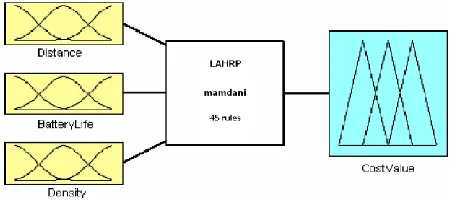
There are three input variables: distance, battery life and processing density in fuzzy reasoning system. The output variable is only cost value. The fussy system was built using membership functions as shown in fig. 2.
Fig. 2. Fuzzy System used to obtain cost value.
- Distance changes from 0 to 100
l
T . Five trianglemembership functions are equally replaced between 0 and 100: very close (0-0-25), close (0-25-50), medium (25-50-75), far (50-75-100) and very far (75-100-100).
- Density and battery life vary from 0 to 100 percent. Three membership functions for these input variables: low (0-0-40), medium (10-50-90) and high (60-100-100).
- Cost value, varies from 0 to 100 units. Five membership functions for this output variables: very low (0-0-25), low (0-25-50), medium (25-50-75), high (50-75-100) and very high (75-100-100).
Fussy system fuzzifies the input crisp data and then with Mamdani [15] inference system applies the 45 rules. Center of gravity method has been used for defuzzyfication of output variable. Consequently, the cost value of each node to other nodes (if they are within coverage) has been obtained. The cheapest path has been obtained by means of Bellman Ford or Dijkstra’s optimizations algorithm in order to achieve the optimization process given in item “k” of algorithm step in section 2.1.
3. PERFORMANCE EVALUAT ION
3.1
Simulation Setup
Simulation is done on the GloMoSim developed at the UCLA labs. It is being used to test the protocols of the wireless networks. The simulator provides a proper model for the signal propagation and its radio model supports a 2Mbps of transmission rate and 100 meters of transmission range. The IEEE 802.11 was simulated at the MAC layer, with the implementation of the distributed coordination function (DCF). In this simulation, 50 mobile nodes move within a rectangular field of 500m x 500m in size. We choose this rectangular field so that the average hop distance between any two nodes will be larger than that of a square field with the same area. The duration of each run is 100 simulated seconds. The mobility model uses the random waypoint model. The radio model used is the two ray model. We change the mobility rate by setting different values to pause time as 0, 10, 20, 50 and 100 simulated seconds. Here, a pause time of zero means continuous mobility and 100 seconds reflects stable nodes. The maximum moving speed can be 20m/s. We run simulations covering each combination of pause time and moving speed. For the traffic model, we use 20 simultaneous sessions with source-destination pairs spreading randomly on the whole network. Traffic sources are constant- bit-rate, sending 4 UDP packets a second. Each packet is 512 bytes long, thus resulting 2K byte per second data transfer rate for each session.
3.2 Performance Me trics
- Normalized routing load: is the number of control packets per data packets transmitted in the network.
- Packet delivery Ratio: it is the ratio of the number of packets which received successfully and the total number of packets transmitted.
- Average end-to-end delay: the end-to-end delay is averaged over all surviving data packets from the sources to the destinations.
The simulation results are presented in the next section.
3.2
Simulation Results
The results obtained after simulation are compared with the well known reactive routing protocol DSR. Fig. 3 shows the normalized routing load for LAHRP and DSR algorithms
0 0.1 0.2 0.3 0.4 0.5 0.6
0 50 100 150
Pause Time (s)
N
o
rm
a
li
z
e
d
R
o
u
ti
n
g
L
o
a
d
DSR LAHRP
Fig. 3. Normalized routing load vs. Pause time
It is noticed that the normalized routing load value of LAHRP is lower than DSR routing algorithm. This is the result of reducing the routing overload with the proposed algorithm especially in case of high mobility. Reducing routing overload in network will supply effective usage of bandwidth and energy consumption.
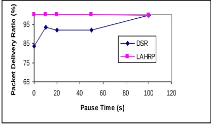
Fig. 4 shows the packet delivery ratio of LAHRP compared with DSR. The packet delivery ratio is higher for our algorithm as it is compared with DSR routing algorithm.
65 75 85 95
0 20 40 60 80 100 120
Pause Time (s)
P
a
c
k
e
t
D
e
li
v
e
r
y
R
a
t
io
(
%
)
DSR LAHRP
Fig. 4. Packet delivery fraction vs. Pause time
LAHRP was compared with DSR in terms of average end-to-end packet delay in Fig. 5.
0 10 20 30 40 50 60
0 20 40 60 80 100 120
Pause Tim e (s)
A
v
e
ra
g
e
d
E
n
d
-t
o
-e
n
d
D
la
y
(m
s
)
DSR LAHRP
Fig. 5. Average end-to-end delay vs. Pause time
It is noticed that the LAHRP has better performance than the DSR algorithm.
4. CONCLUSION
In this paper, we propose a new routing algorithm called LAHRP for optimizing band-width usage and decreasing energy consumption by reducing routing overload for MANETs. The proposed LAHRP algorithm is compared with the DSR algorithm in terms of normalized routing load, packet delivery ratio and end-to-end packet delay. It was observed from performance simulation that the LAHRP gives better results than DSR algorithm especially in the case of high mobility. The LAHRP algorithm uses available bandwidth efficiently because of its high packet delivery ratio and low normalized routing overload. The algorithm is not affected with the number of nodes increased in the network. It only increases the size of routing matrix held by master node.
On the other hand, this drawback could be removed by clustering procedure of network. The nodes are clustered according to their geographically closeness of each other. Clustering speeds up the route determination process.
REFERENCES
[1] Siva Ram Murthy, C. and B. S. Manoj. Ad hoc Wireless Networks: Architectures and Protocols. 1st Edn. , Prentice
Hall, USA, pp: 880, 2004.
[2] Ehsan H, Uzmi ZA, “ Performance Comparison Of Ad Hoc
Wireless Network Routing Protocols,” Proceedings of INMIC, pp. 475- 465, Dec. , 2004.
[3] Abolhasan M, Wyosocki T , Dutkiewicz E, “ A review of routing protocols for mobile ad hoc networks,” Journal of ad hoc networks 1: pp. 1- 22, 2004.
[4] Johnson D. B., Maltz D. A, “ Dynamic Source Routing in Ad-Hoc Wireless Networks, ” Mobile Computing T omasz Imielinski and Hank Korth, chapter 5, pp. 153 - 181, Kluwer Academic Publishers, 1996.
[5] Perkins CE, Royer EM, “ Ad-Hoc on Demand Distance Vector Routing,” Proc. of 2nd IEEE Wksp. Mobile Computer Applications, pp. 90-100, 1999.
[6] Haas Z, Pearlman M, “ T he Performance of Query Control Schemes for the Zone Routing Protocol,” Proc. of ACM SIGCOMM '98, Vancouver, 1998.
[8] Stajmenovic I, “ Position Based Routing in Ad Hoc Networks,” IEEE Commun. Magazine, Vol. 40, No. 7: pp. 128-134, 2002.
[9] Basagni S, Chiamtac I, Syrotiuk V. R., Woodward B. A., “ A Distance Routing Effect Algorithm for Mobility (DREAM),” Proceedings of the 4th International Conference on Mobile Computing and Networking, Dallas, T exas, US, pp. 76-84,1998.
[10]Stajmenovic I, Seddigh M, Zunic J., “ Dominating Sets And Neighbor Elimination Based Broadcasting Algorit hms in Wireless Networks,” IEEE T ransactions on Parallel and Distributed Systems, Vol. 13, pp. 14- 25, January, 2002. [11]Lin X, “ GPS based localized routing algorithms for wireless
Networks,” Bsc T hesis, Ottawa- Carleton Institute for Computer Science School of Information T echnolo gy and Engineering, pp. 25- 29, 1999.
[12]Imielinski T , Navas J. “ GPS Based Geographic Addressing Routing and Resource Discovery,” Communications of t he ACM 42: pp. 86-91, 1999.
[13]Watanabe M, Higaki H., “ No-Beacon GEDIR: Location-Based Ad-Hoc Routing wit h Less Communication Overhead,” International Conference on Information T echnology (IT NG’07), pp. 48- 55, 2007.
[14]Recep Demirci, “Similarity relation matrix-based color edge detection”, International Journal of Electronics and Com m unication (AEÜ), Available online at
www.sciencedirect.com
[15]Mamdani, E. H. and Assilian S., “ An experiment in linguist synthesis with fuzzy logic controller,” Int. J. Man-Machine Studies, 7: pp. 1-13, 1975.
[16]Speetzen A., Junius M., Steppler M., Buter M. and Pesch D., “Communication Network Class Library,” ANSI/ IEEE std. 802.11,1999
BIBLIOGRAPHY
▲Name: Dr. Mamoun Hussein Mamoun.
Addre ss: Faculty of Computer and
Information Sciences, Mansoura
University, Egypt.
Educati on & Work e xpe rie nce : has completed B.S. degree in electrical and computer engineering from Military T echnical Collage (Egypt) in June 1979, his M.S degree in electrical and computer engineering from Cairo University (Faculty of Engineering) in Oct. 1985 and PhD degree in electrical and computer engineering from Cairo University (Faculty of Engineering) in Dec.1990.His research interests including Routing and Multicast for MANET . Presently he is working as Associate Prof. in Faculty of Computer and Information Sciences, Mansoura University, Egypt.
Te l: +2023763412