Abstract—In order to study on the punching shear behavior of spread footing with specially shaped columns, the spread footing with rectangular column was simulated by MSC.Marc firstly, the load-deflection curve and punching process of the simulation is consistent with the experiment. Then simulations of foundations with cross-shaped, T-shaped and L-shape column were carried out based on this, which show punching bearing capacity of the cross column is greater than that of T and L. Furthermore, these footing with specially shaped columns were calculated according to ACI 318 and LIU Wenting’s paper, punching shear strength of cross-column, T-column and L-column of the simulation are 1.21 times, 1.12 times and 1.09 times as high as the calculation. The comparison between calculation and test of 99 spread footings with rectangular column show that the test values are 1.25, 1.21, 1.42 times the calculation by CB5007, BS8110 and EN 1992. Therefore, the simulation in this paper is credible and can be used for the in-depth analysis of the spread footing.
Index Terms—Finite element modelling, specially shaped columns, spread footing, punching shear failure.
I. INTRODUCTION
Punching shear damage of spread footing is defined that the cracks first appear in the shear-moment regions of foundation slab, then cracks are constantly expanding, column finally is separated from the base plate with a punching cone. By this time, the bending steel is not yielding, the destruction is very sudden and without warning, the result of brittle damage is very serious. Therefore, the resisting punching capacity should be considered firstly in the designing.
However, the study on punching performance is mainly about reinforced concrete rectangular columns at home and abroad at present. But, the cross-section area of the rectangular column becomes larger with the increment of building height, this will result in the width of the column is greater than the thickness of the wall in vertical and horizontal wall junction, in addition, a series of problems are continuously emerging, such as influence the beauty of the room and not conducive to furniture placement, etc. So the L-shape, T-shape and cruciform column are becoming more and more popular among designers. Reference [1] and [2] are
the technical specification for structure with special shaped columns and foundation code of China, but which don’t specified the punching influence of the special-shaped column on the floor and foundation, Although European and
Manuscript received October 30, 2017; revised March 12, 2018. Xiufeng Xu is with the Qingdao Huanghai University, Qingdao, PC 266000 China (e-mail: [email protected]).
Zi’ang KONG is with Qingdao Greentown architectural design Co., LTD, Qingdao, PC 266000 China (e-mail: [email protected]).
American code [3]-[5] define the critical section of cruciform, but the L shape and T column are not explained. The designers design the footing with specially shaped column can only by the experience or calculate through the equal area of rectangular column, this will make the calculation result and the actual result have a great error. Simulation is made by the finite software MSC.Marc in order to study the influence of different column cross section shapes on the punching shear behavior of spread footing. In order to prove the validity of numerical simulation, the first simulation was the rectangular column foundation test in [6], the contrast of simulation value and test results shows that the simulation is right. Then, studying on the punching performance of three kinds of typical special-shaped columns (L-shape, T-shape and cruciform) based on it. Lastly, the calculation formula of the punching shear capacity in [3] and the calculation formula of the critical section in [7] were used to calculate these special-shaped column foundations. The calculated results are conservative by comparison with the simulation results, however the comparison between the test results of 99 spread footings with rectangular column in [8] and calculated results shows that the numerical simulation method and calculation method in this paper are feasible, which can be used as the basis for the in-depth analysis of the punching performance of the spread footings and provides reference for engineering design.
II. VERIFICATION OF MODEL
A. Introduction of Test Model
The spread footing test in [6] was selected as the simulation object of MSC.Marc software, the base plate size is 1450mmx1050mm, its thickness is 220mm, the column size is 250mmx250mm, the strength of concrete and reinforcement are 38.3MPa and 370MPa, the placing of steel bars of foundation is shown in Fig. 1, the reinforcement rate is 0.36%.
8B16
1
1
1450
220
300
250
250
A8@100
A10@100
A8@100
1-1
Fig. 1. The reinforcement figure of foundation.
The Simulation of Punching Shear Behavior of Spread
Footing with Specially Shaped Columns
B. Introduction of Simulation
Concrete structures were modeled by solid element, rebar used truss element to simulate and were embedded into the concrete structure through the Insert function in Marc software. During the loading process, fastened the top of the column and imposed the base counterforce distribution model got from the test to the bottom of base plate for simulating the impact of soil on foundation.
The concrete constitutive relation in simulation was thought up by E.Hognestad recorded in [9], which calculation formula is shown in formula (1), ε0=0.002,εu=0.0033, σ0=0.85fc’ (fc’ is the compressive strength of concrete cylinder). The yield criterion used Buyukozuturk in Marc software, reference [10] notes that the stress-strain relationship is equivalent stress - equivalent plastic strain relation when using this criterion.
2
0 0
0 0
0 0
0 [2( ) ( ) ]
[1 0.15( u )] < u u (1)
The constitutive relation of reinforced was ideal
elastic-plastic constitutive in [11], as formula (2), εy means
yield strain, εy=fy/E. The yield criterion used the Von
Mises yield criterion, the hardening rule adopted the kinematic hardening model.
=
,
, >
s y y y
E
f
(2)C. Comparison of Simulation and Experimental Results
The contrast of load-deflection curves obtained from simulation and test are shown in Figure 2, the deflection of the base plate in the graph is calculated by formula (3), Lshort is the short edge size of foundation, H is vertical displacement of each point, the points are shown in figure 3. The load-deflection curve of simulation shows that the curve has an obvious inflection point when the load increases to 733kN, which represents that the foundation is basically destroyed, then the deflection increases rapidly but the load growth is small, which is basically match with the phenomena “the deflection of the base plate increases rapidly when the load is 750kN and the cracks in the foundation plate are carried out rapidly” observed form [6]. The comparison between the test curve and the simulation curve shows that the deflection of simulation is slightly smaller than the test in the same load, probably due to the Insert function embeds the steel bar in concrete unit without considering the bond slip between them, result in the stiffness of the model becomes larger and the deformation becomes smaller, but the overall trend of the curve fits well with the test curve.
short /
1- 1 + 2- 2 + 3- 3 + 4- 4
=
4 f H L
H H H H H H H H H
( ) (3)
0 10 20 30 40 50
0 200 400 600 800 1000
D ef le c ti o n ( ‰) Load(kN) Simulation Test 730kN
Fig. 2. Compare the simulation with the test of Load-deflection curve.
Fig. 3. Definition of deflection.
Fig. 4. Cracks appear at the bottom of foundation plate.
0 10 20 30 40 50
0 200 400 600 800 1000
D e fl e c ti on (‰) Load(kN) 600kN
Fig. 5. The crack extends outwards.
0 10 20 30 40 50
0 200 400 600 800 1000
D e fl e c ti on (‰) Load(kN) 667kN
Fig. 6. The crack extends upward.
0 10 20 30 40 50
0 200 400 600 800 1000
挠度(
‰
)
荷载(kN)
0 10 20 30 40 50
0 200 400 600 800 1000
D
e
fl
e
c
ti
on
(‰)
Load(kN)
733kN
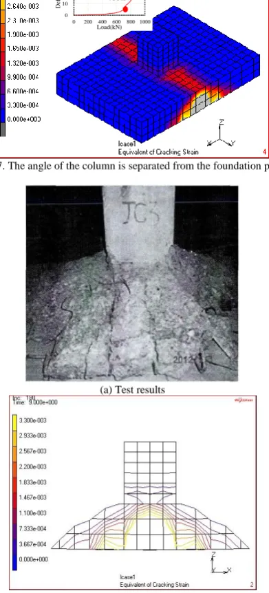
Fig. 7. The angle of the column is separated from the foundation plate.
(a) Test results
(b) Simulation results
Fig. 8. Comparison of foundation punch failure between test and simulation.
The equivalent cracking strain contours show that cracks appear at the base plate along the length direction firstly when the load is 539kN, as shown in figure 4. As the load continues to increase, the crack gradually expands outward and upward, as shown in figure 5 and figure 6. The crack extends to the foot of the column when it is loaded to 733kN, the center cone begin to sink and disengage from the surrounding area gradually until the punching shear failure , as shown in figure 7. Figure 8 is the ultimate failure mode of numerical simulation and experiment, it shows that the destructive state of them are basically the same.
III. SIMULATION OF SPREAD FOOTING WITH SPECIALLY SHAPED COLUMNS
A. Introduction of Spread Footing with Specially Shaped Columns
This paper mainly studies on the punching shear behavior
of spread footings with cross-column, L-column and T- column. The columns were reinforced by the technical specification of the concrete special-shaped column structure, the reinforcement situation is shown in figure 9, the longitudinal reinforcement are all 8C16+4C14, the longitudinal reinforcement ratio is 1.15%, the stirrup is
C8@100, the stirrup ratio per unit volume is 1.42%. The foundation plate size is 1300mmx1300mm, the thickness of plate and the height of specially shaped columns are all 500mm.
Fig. 9. Reinforcement figure of special-shaped columns.
B. The Result of Simulation
The load-deflection curves of three kinds of spread footing with specially shaped columns from simulation are shown in figure 10. The punching shear strength of cross-column, L-column and T- column respectively are 3128kN, 2999kN and 2958kN, moreover, the punching failure of three kinds of foundation are happened at a smaller deflection, there are almost no obvious plastic deformation in the process of destruction, the characteristics of brittle fracture are obvious. The equivalent cracking strain contours when reach the punching bearing capacity are shown in figure 11~13. The simulation shows that the bearing capacity of the cross-column is highest and breaking is lowest when the size of the column and the ratio of the reinforcement are the same.
0 0.5 1 1.5 2 2.5 3 3.5 4
0 600 1200 1800 2400 3000 3600
D
ef
le
c
ti
o
n
(‰
)
Load(kN) cross-column T-column L-column
Fig. 11. The cracking strain nephogram of T column.
Fig. 12. The cracking strain nephogram of T column.
Fig. 13. The cracking strain nephogram of L column.
IV. CALCULATIONS
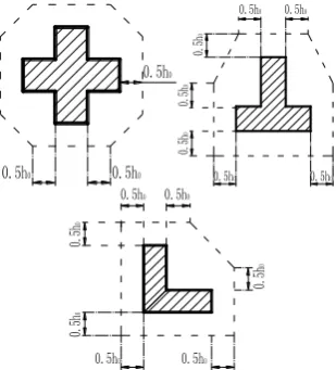
In this paper, the bearing capacity of three kinds of spread footing with specially shaped columns were calculated based on the calculation formula of reference [3]. The formula is shown in formula (4), fc’ is the compressive strength of concrete cylinder, d is effective height of the foundation, b0 is critical section perimeter, the critical section of the cross-column was evaluated according to [3], the critical section of L-column and T-column were calculated according to the reference [7], because of there are no regulation in domestic and foreign norms about that. The critical cross section of these three foundations are shown in Fig. 14.
'
c
0.33
c 0V
f b d
(4)Fig. 14. The perimeter of the critical section.
Table I shows the comparison of punching shear strength between the simulation results and the calculation results, punching shear strength of cross-column, T-column and L-column of the simulation results respectively are 1.21 times, 1.12 times and 1.09 times as high as the calculation results. The formulas of CB5007, BS8110 and EN 1992 were used to calculate the punching strength of 99 spread footings with rectangular column in reference [8], the ratio of test results to calculated results is shown in table II, which shows that China's norms is closer to the American standard, the test values are 1.25 and 1.21 times the calculation respectively. The comparison between table I and table II shows that the simulation results are bigger than the calculation is reasonable. Therefore, we can use the numerical simulation method in this paper to further study the punching shear behavior of spread footing with specially shaped columns.
TABLEI:THE CONTRAST BETWEEN THE SIMULATION AND CALCULATION OF PUNCHING STRENGTH
Shapes
fc’
/N/mm 2
b0 /mm
d/m m
Vc/kN
Simulate / Calculate Calculat
e
Simulat e
Cross
25.4 450
3 448 2 581 3 128 1.21
T 3 570 2 672 2 993 1.12
L 3 624 2 713 2 958 1.09
TABLEII:THE RATIO OF THE TEST VALUE TO THE CALCULATED VALUE OF PUNCHING STRENGTH
GB 50007 ACI318 EN 1992
Mean value 1.25 1.21 1.42
Standard
deviation 0.37 0.36 0.25
V. CONCLUSION
greater than that of T and L, The comparison between simulation results and calculation show that the load bearing capacity of the numerical simulation is reasonable, therefore, the simulation in this paper can be used for study on the impact factors on punching of the spread footing with specially shaped columns in depth. At the same time, the calculation method of the shear bearing capacity of spread footings with special-shaped column can provide reference for engineering design.
REFERENCES
[1] Technical Specification for Concrete Structures with Specially Shaped Columns, China Building Industry Press JGJ 149-2006. [2] Code for Design of Building Foundation, China Building Industry
Press GB 50007-2011.
[3] Code Requirements for Structural Concrete and Commentary, American Concrete Institute, ACI 318-08.
[4] Design of Concrete Structures, The authority of the Standards Policy and Strategy Committee of England EN 1992-1-1:2004.
[5] British Concrete Structure Specification, China Academy of Building Research Beijing: (translation) , BS 8110.
[6] L. Rongnian, “Research on the calculation method and failure characteristics of shear of spread footings,” Ph.D. dissertation, Dept. Geotec. ENG., China Academy of Building Research, Beijing, China,2013.
[7] L. Wenting, “Study on design theory of RC flat plate structure with special columns,” DaLian: Dalian University of Technology, 2003. [8] Y. Kai, “The reliability analysis of reinforced concrete slabs in
punching shear,” M.S. thesis, Dept. Architectural. and Civil ENG., Hunan Univ., Hunan, China, 2012.
[9] J. J. Jiang and X. Z. Lu, Finite Element Analysis of Concrete Structure,
Beijing: Tsinghua University press, 2013, pp. 44-45.
[10] X. Z. Lu, L. P. Ye, and Z. W. Miu, Elasto-Plastic Analysis of Buildings Against Earthquake, Beijing: China Architecture & Building Press, 2010, pp:144-146.
[11] Code for Design of Concrete Structures, China Building Industry Press GB50010-2010.
Xiufeng Xu was born in China, in 1987. She received
her doctorate in engineering from Institute of Engineering Mechanics, in China, in 2015 Her major field of study is structural earthquake-resistant. She is a lecturer of Qingdao Huanghai University,
The papers published by her as follows: “X. F. Xu and T. Wang, “Evaluation and simulation of experimental damage of a retrofitted masonry structure,” Earthquake Engineering and Engineering Dynamics, 2015, vol. 35, no. 6, pp. 8-17; “X. F. Xu and X. T. Wang, “Seismic performance analysis of precast panels with shaped-steel boundary constraint components,” World Earthquake Engineering, 2014, vol. 30, no. 3, pp. 93-101; X. F. Xu and T. Wang, “Numerical study on precast RC wall panels with angle steel boundary components,” Applied Mechanics and Materials Vols, pp. 351-352, 2013, pp. 278-582.
Zi’ang Kong was born in China, in 1987. He
received her doctorate in engineering from Institute of Engineering Mechanics, in China, in 2016. His major field of study is structural earthquake-resistant.
He is a civil engineer of Qingdao Greentown architectural design Co., LTD.
The papers published by him as follows: Z. Kong and T. Wang, “Experimental study on mechanical properties of steel dampers with slits,”