22 & 23.04.2017
In association with
I
nternational
Journal of
Scientific
Research in
Science and
Technology
Enhancement of Hybrid Power Scheme Based on Genetic
Algorithm Using Three DC Source
*1 U. Ramani, Department of Instrumentation and Control Engineering, Kalasalingam University, Virudhunagar, Tamailnadu, India [email protected]
2 Dr. B. Kannapiran, Department of Instrumentation and Control Engineering, Kalasaligam University, Virudhunagar, Tamilnadu. India kannapiran79@ gmail.com2
ABSTRACT
Now a day’s Solar Power is essential for all domestic purposes due to the demand of power consumption. But the single Solar system doesn’t give the consistent yield due to sun power illumination. To conquer this issue, this project work presents enhancement of hybrid power scheme utilizes with PV/Fuel cell/Battery power to produce constant power using genetic algorithm (GA). The proposed hybrid scheme initially utilizes four module power controllers for independently expose to different duty cycles. The constant DC source is carried out by hybrid power scheme is to optimize the different duty cycle and to provide constant voltage through the load. This paper presents Genetic algorithm (GA) based model to enhance the duty cycle of the controller for a hybrid power control scheme. The simulation result was carried out by MATLAB/SIMULINK. From the model, the data required are generated and the performance is analyzed using a genetic algorithm. The GA based approach indicates better performance when compared with neural network controller.
Keywords: Hybrid DC source, Genetic algorithm, Duty cycle Enhancement.
I.
INTRODUCTION
This document is a template. The standard fossil fuel vitality such as petroleum, natural gas, and coal are takes care of power demand in this day and age. The renewable vitality sources (solar, the wind, tidal, geothermal, etc.,) have more attention as an alternative vitality. In this paper, the photovoltaic (PV) vitality appears stopped to attract for electricity generation. Since, solar power grid generation relies on the sun illumination stage, encompassing temperature and eccentric darkness of PV [1, 2].
Fuel cell (FC) [2, 3, 4] exhibited to design the promising of extra power source that are advantages of neatness, more effectiveness, and prominent unwavering quality. For the most part, FC is perform extended turn on process and is carried out minimum time-consuming process of dynamic response to bungle power between the loads.
Batteries are for the most part taken a capacity component for charging and discharging power to improving the transitions of dynamic characteristics. Consecutively, the three power scheme initialized by the DC source of PV/FC/Battery [5], which is known as hybrid power scheme. When evaluation individual sourced system as well as hybrid power scheme has to certainly offer by more quality output reliable and more efficiency. In this system consists of a storage feature, with utilize the power exist of bi-direction voltage flow. These three information control sources produce a decent capacity to supply voltage to the load alone.
amount of devices utilize the process provides high power losses. Here, quite a few stage of power conversion are utilizes the hybrid power scheme, which are changed by a three input converter. Thus, the result of process is consolidated through various power sources in individual structure. To defeat the problem suggested the boost converters having additional advantages of multi-objective optimization approach for hybrid power scheme by changing the duct cycle values randomized for developing the constant power deliver to the load. This paper deals with the multi-input dc-dc boost converter maintain the constant output voltage, to optimize the hybrid power system and fast output response using a genetic algorithm (GA).
Three input cuck regulated model fuzzy logic design [7] to interfacing the wind energy sources produce the electrical energy in to the system. This type of fuzzy the logic controller can be deliver yield streams relating to each power station and their reference voltage. DC-DC converter for battery [8] presents a controller is proficient to operating in bidirectional and to regulate the constant output voltage under different inputs values. The MPPT control algorithm present [9] that includes automatic determination and to permits the conventional converter of optimal operation control circuit under steady state environment with different duty cycles. DC-DC boost converters [10] present a design of integrated photovoltaic by applying back propagation artificial algorithm was produced boosted output voltage and sudden changes for solar illumination levels.
Modeling and design of regulated power supply approaches proposed [11] system conveying output source for converter topology with using a genetic algorithm (GA).This output impacts of parameters such like that increasing population size, iteration value, and varying the probability of mutation and probability of crossover also presented using MATLAB/SIMULINK.
Optimization of boost converter power loss was presented [12] a design of converter switching operation can be controlled, voltage swells by using an optimization technique. Utilizing these techniques easily obtained constant boosted output voltage by MATLAB. Hybrid power scheme optimization model were proposed for the design of [13] solar and wind energy system. This power scheme comprises of solar cells, wind turbines, and storage batteries are optimized using
objective function. This function optimized the total cost, initial cost, and yearly replacement cost can be maintained in the proposed converter.
Three input dc-dc converter was presented [14] fuel cells and battery packs are used to compensate for the immediate power changes in the microgrid that problem exhibits to the un even power loss of solar cells are required to the microgrid, and resultant of that power lose occurs sudden intrusion of the main grid. To overcome this losses using enhancement technique for three input dc source provide low level settling time and rise time in their grid connected system.
Optimization of hybrid energy system presented [15] an endeavour to convey the concept of the hybrid renewable energy system (HRES) and the condition of different values can be used to improve the simulink results. The enhancement techniques are used to reduce the swells and produce high output voltage for the microgrid application. Enhancement methods are utilized to reduce the investment cost and reliable resource.
II.
DIFFERENT MODES OF OPERATION
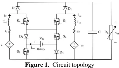
The circuit comprise of a four MOSFET performs effectiveness of controlled with the independently depends on four duty ratios such as d1 d2 d3and d4. Fig .1 performs with boost converter diodes D1 and D2 lead correlative way with comparing switches S1 and S2.
Referring this circuit when the switches S3 and S4 are get started with great operating mode and then possible of corresponding diodes D3 and D4 are biased followed by the complex criteria of battery voltage. These two switches turn-OFF state, the diodes D3and D4, ready to lead conduct the input currents iL1 , iL2
In this circuit is hybrid power system applications and continuous current mode (CCM) is conceivable. It has the converter topology is seen from the solar or Fuel cell systems, an major problem is to reach an sufficient current swell and kept up the consistent yield voltage. The continuous current swells as well as input power are limited to make a correct power adjust along with the input powers simultaneously carried out the load. Consequently, the proposed hybrid scheme converter has been acquired the relentless state yield and quick yield reaction of the converter.
For the usually utilized condition occur of the storage element are considered by the DC modules with operation performs three modes, which are characterized to the proposed hybrid power scheme converters. These distinctive operation conditions are satisfied with d3, d4 <minimization (d1,d2) duty cycle ratios . While exceeding the process of duty ratio does not a failure in this converter. To defeat this issues always consider as the duty cycle ratio d1 is smaller than duty cycle ratio d2, then only switches are operated as autonomously.
A. Mode1:
In the mode 1, v1and v2 charged power sources are providing through the load and without battery storage. That is fundamental modes are done in this mode to control the yield voltage. As unmistakably observed from the basic circuit topology, there are two approach to direct control of input power sources streams iL1,iL2. Without experiencing the battery;
Current flow direction 1: S4–D3 Current flow direction 2: S3–D4.
The working principal of mode 1 is feasible for applying the primary way. According this position switch S4 is OFF and diode D3 also OFF condition. The exchanging states are portrayed in Fig 2-4.
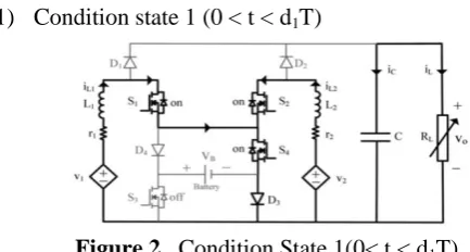
1) Condition state 1 (0 < t < d1T)
Figure 2. Condition State 1(0< t < d1T)
In the main operation mode, at t = 0 the state of Switches S1and S2are turned ON until the inductors L1and L2are charged over the voltages v1and v2 separately.
2) Condition state 2 (d1T < t < d2T)
Figure 3. Condition State 2 (d1 T < t <d2 T)
In stage 2, the operation technique of t = d1T are finished by Switch S1will to low state and this time switch S2 is continuously ON position ( if d1 is smaller than d2), the inductor L1 is released to the charged voltage v1–v0, and output voltage is conveyed to the load. This circumstance inductor L2 gets charged across the source v2.
3) Condition state 3 (d2T < t < T)
Figure 4. Condition State 3 (d2T < t < T)
In stage 3, procedure of t = d2T condition applicable of switch S2 will be proceeds for quite little provided the voltage. While, the inductor L2 is clearly decompose the voltage level beyond the v2–v0 voltage as similar to the inductor L1. This operation is satisfied by the conventional theory as followed the voltage and current the associated by the condition are acquired with output
response .
cycle values and the next power source is used to coordinate the output voltage.
B. Mode 2:
In the second mode, voltage source v1 and v2 along with the battery discharging state is incorporated for providing through the load. The basic converter circuit (Fig 1), the MOSFET switches S3 and S4 are turned ON. This procedure releasing is happened at whatever point the stream of current is between the iL1 and iL2.
In any case, the discharging of the battery can just a single of the switches S1 or S2 is kept in ON position. This mode can be gotten by the resultant of maximum power. At this time duty cycle ratio diodes d1and d2, the corresponding inductors current flow through the iL1 , iL2.
Duty ratio d4 as followed by the condition should be control the discharging power module of battery, which is concerning the certainties process continuously with occurs the mode switch S4 operates with quite high condition. Then, it comes about passing through the currents iL1 , iL2 provides for input belongs to the battery. As delineated in Fig 5-8, there are four attractive processes are operates by the DC converter module, as its individual exchanging state.
1) Condition state 1 (0 < t < d4T)
Figure 5. Condition State 1 (0 < T < d4T)
In stage1 t= 0 switches S1, S2, and S4 are absolutely greater than the other switches that instantaneously process of inductors L1and L2 are existing improve the level across the voltages v1 + vB and v2 + vB. These charged voltages are given to the load and create the steady output voltage for this switching state 1. Which state works according to the duty cycle ratio (supposition d1<d2) used to turn ON the comparing switches.
2) Condition state 2 (d4T < t < d1T)
Figure 6. Condition State 2 (d4T< t < d1T)
In stage2 t = d4T at this issues time switch S4 is killed, while the switches S1 and S2 are quite with the higher than the others, which condition provides for inductors L1and L2 are obtained with increase the voltage level across the v1 and v2 respectively.
3) Condition state 3 (d1T < t < d2T)
Figure 7. Condition State 3 (d1T< t < d2T)
In stage 3 t= d1T at this condition switch, S1 is execute with under low condition the meantime of inductor L1 is simultaneously degrades the voltage beyond v1– v0 at this stage L2, is quite accused of voltages across v2.
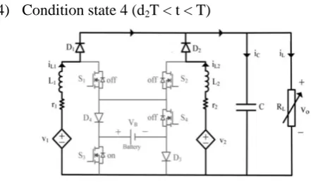
4) Condition state 4 (d2T < t < T)
Figure 8. Condition State 4 (d2T < t < T)
voltage and current the associated by the condition are acquired with output response .
In mode 2 is carried out by the v1 and v2 input power sources are referred to get the resultant of the duty ratios d1, d2 and the battery degrades as well as the power utilized balance output voltage by the limited duty cycle ratio d4.
C. Mode 3:
In mode 3 provide for one or more different input source of v1and fuel cell v2are greatly extension of voltage as well as providing through the load and battery charging execution are incorporated into this mode.
As observed from the converter circuit, when the switches S3and S4are goes excessively turned OFF at these time switches S1and S2 are quite higher than the others switches, then the inductor iL1 and iL2 provides the currents simultaneously followed by the access of diode D4, battery and diode D3. According to the condition battery is concurrently attended. The charging power is underneath the Pmax esteem charging, to change the condition state of a one set of the switches S3,S4 earlier than the switches S1, S2 goes to high state.
According to the condition state of this operation mode, when the switch S3 is turned ON right now battery is holding off on charging until the switch goes too turned OFF state. These conditions state are illustrated in Fig 9-12.
1) Condition state 1 (0 < t < d3T)
Figure 9. Condition State 1 (0 < t < d3T)
At this arrangement 1 t = 0 conditions that happens with the MOSFET S1, S2 and S3 are greatly higher state compare to other states as shown fig.9.simultaneously the inductors L1and L2 are accused by the v1and v2, correspondingly.
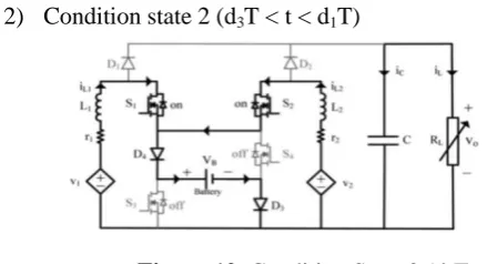
2) Condition state 2 (d3T < t < d1T)
Figure 10. Condition State 2 (d3T < t < d1T)
In stage 2, t = d3T, this condition is fulfilled by low state of the switch S3 and the MOSFET switches S1, S2 are at a standstill greater condition, and the inductors L1and L2 to get charged through make use of the v1− vB and v2− vB, separately.
3) Condition state 3 (d1T < t < d2T)
Figure 11. Condition State 3 (d1T < t < d2T)
followed the voltage and current the associated by the condition are acquired with output response
4) Condition state 4 (d2T < t < T)
Figure 12. Condition State 4 (d2T < t < T)
In arrangement 4, t = d2T condition is satisfied by the condition of low state switch S2 and the inductor L2 , L1is released make use of the voltage v2− v0.
III.
PROPOSED METHODOLOGY
Genetic algorithms are the most specified analysis ideal approaches to solve a complex optimization problem. This approach can be extremely broad calculation and can function admirably in any pursuit space. The genetic algorithm is proficient to produce an exact the expert solution. This algorithm also produces several solutions to a given problem.GA is standout amongst the powerful methods with which to quick response to create an exact the expert solution for a specified problem. GA consists of the three frame work followed by the exact solution of essential population to arrange the many random values to evolve condition such as selection rules, crossover and mutation process as well as providing the better solution of the fitness function. This problem solve the required fitness function is minimizing the maximum rise time and settling time.
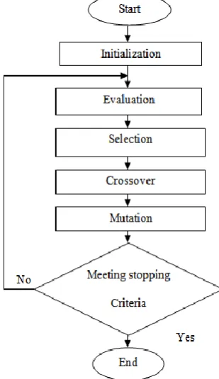
Figure 13. Flow chart of the genetic algorithm.
GA procedure based on the flowchart of fig 13.intially the GA select the parameters randomly for population size at initial stage and then produce the children from parents. This parent produces the children for next generation by using genetic algorithm flow chart.
IV.
RESULTS AND DISCUSSION
In this paper, GA is used to optimize the duty cycle ratio in order to minimize the rise time and settling time. The boost converter duty cycle ratios are optimized by using MATLAB/Simulink. The optimized duty cycle values are obtained by using the objective function. Now the population size is 100, initial population size is 1and iteration value is 10. After the iteration can able to satisfy the minimum rise and settling time to produce the constant output voltage for proposed converter. Generally, the dc-dc boost converter duty cycle objective function as follows:
D =∑
(10)
Where Ts is the Rise time,
T = Ton+Toff .This duty cycle ratio values can be obtained by MATLAB/Simulation result. After the simulation duty cycle values are saved in workspace file. Whenever applying the gate pulse to the proposed converter and take saved duty cycle ratio values are consider. The best optimal solution is obtained by changing the population size. Optimization results after 10 iteration as follows as:
Parameter Values Number of
population size
100
Crossover Probability
1.0
Mutation probability 0.00001 Fitness value 0.006
Table 1. Parameters used in GA
This table 1.shows the parameter used in GA in order to optimize the duty cycle ratio. By selecting the population size as 100, the crossover probability as 1.0, mutation probability as 0.00001and the fitness value as 0.006. The simulation block of GA used for duty cycle optimization using MATLAB is shown in fig 14.
Figure 14. Duty cycle optimization using MATLAB.
Fig14.optimized values are given to the pulse generator and produce the duty cycle waveform for corresponding converter circuit in order to optimize duty cycle ratio.
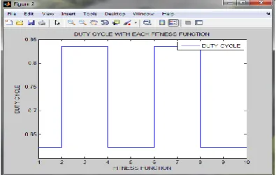
Figure 15. Duty cycle optimization Simulation
The duty cycle is optimize in the range of 0.85 is shown in Fig 15 with the given fitness values of 0.006 the duty cycle is optimized and by changing the fitness values of duty cycle can also be varied. This boosted output voltage waveform produces only after the 10th iteration and corresponding duty cycle ratio is used in this converter with the given values, the duty cycle is optimize as 0.85 and the corresponding boost output voltage using GA is shown in Fig 16.
Figure 16. Boost output voltage using GA
V.
COMPARISION OF ANN AND GA
SIMULATION RESULTS
The GA model provides for duty cycle optimization of DC-DC boost converter from hybrid power scheme. The rise time required is 0.0005sec and settling time 0.009sec. For performance comparison ANN model was developed the rise time 0.005sec and its settling time 0.01sec. On comparing the performance of GA model with ANN model, the GA model shows better performance when compared with ANN model. Fig 17 is obtained the constant voltage level proceeding with proposed method under different operation mode for a hybrid power system using GA and also obtained better performance of settling time (Ts) and rise time (Tr), which this condition to maintain the continuously constant power delivered to the load.
Figure 17. Boost output voltages using
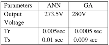
The same problems were solved by the artificial neural network controller to obtained less settling, rise time and could not able to control the hybrid power scheme. But compare the genetic algorithm (GA) results is able to control the system and also obtained better optimization performance are given table 2.
Parameters ANN GA Output
Voltage
273.5V 280V
Tr 0.005sec 0.0005 sec Ts 0.01 sec 0.009 sec
Table 2. Comparison between ANN and GA
VI.CONCLUSION
A hybrid power scheme of dc–dc boost converter structure was designed and better performance was obtained using GA. This hybrid power scheme can be apply for a solar (PV), FC, battery storage system and enhancement duty cycle ratios values are applied to the proposed converter circuit. This converter produces the yield output voltage source is obtained by using the Genetic algorithm.
This converter produces 280V helped voltage and fast output response is 0.009sec settling time and 0.0005sec rise time results are obtained by using a genetic algorithm (GA).
VII.
REFERENCES
[1] A. B. Wie. Jiang and B. Fahimi, “Active current sharing and source management in the fuel cell-battery hybrid power system,” IEEE Trans. Ind. Electron., vol. 57, no. 2, pp. 752–761, Feb. 2010. [2] N.Kato,K. Kurozumi, N. Susuld, and S. Muroyama,
“Hybrid power supply system composed of photovoltaic and fuel-cell systems,” in Proc.Int. Telecommun. Energy Conf., 2001, pp. 631–635. [3] Taraksalmi, Mounir Bouzguenda, Adel Gastli, Ahmed
“MATLAB/Simulink Based Modelling of Solar Photovoltaic Cell” International Journal of Renewable Energy Research., Vol.2,No.2, July 2011.
[4] K. Rajashekara, “Hybrid fuel-cell strategies for clean power generation,”IEEE Trans. Ind. Appl., vol. 41, no. 3, pp. 682–689, May/Jun.2005.
[5] Mona N.Eskander, “Energy flow and management of a hybrid wind/PV/fuel cell generation system,” Elsvier., Energy conversion.Nov 2005.
[6] Farzam Nejabatkhah, Saeed Danyali, Seyed Hossein Hosseini, Mehran Sabahi, and Seyedabdolkhalegh Mozaffari Niapour, “Modeling and Control of a New three-input DC–DC Boost Converter for Hybrid Power System”, IEEE Transactions On Power Electronics, Vol. 27, No. 5, May 2012.
[7] Noor-ul-Ain Hanif “Multiplexed control strategy for a multi-input converter using fuzzy logic algorithm”, IEEE Power electronics, vol. 52, no. 15, pp. 1327– 1329, July. 2016.
[8] Zhihao Li, Omer Onar, And Alirezakhaligh “Design and control of Multiple Input DC/DC converter for battery” Journal of Harvesting and Renewable Energies Laboratory (EHREL)., Vol.2, No.2, December 2011, pp.168~174.
[9] M.T. Makhloufi, Y. Abdessemed and M. S. Khireddine, “A Neural Network MPP Tracker Using a Buck- Boost DC-DC Converter for PV Systems”, IEEE 5th International Conference on Systems and Control, Cadi Ayyad University, Marrakesh, Morocco, May 25-27, 2016
[10] N. Jiteurtragool, C. Wannaboon and W. San-Um, “A Power Control System in DC-DC Boost Converter Integrated with Photovoltaic using Back Propagation algorithm Artificial Neural Network”, IEEE 5thInternational Conference on Knowledge and Smart Technology, 107-112, 2013.
[11] Choon-Keat Chew and Siva Ramo Rao Kondapalli “Modelling , analysis, simulation and Design Optimization (GA) of dc-dc Converter for Uninterrupitable Power supply Application IEEE, Power electronics,2005
[12] P.Suresh “Power loss optimization of boost converter using genetic algorithm (GA)”International Journal of Scientific & Engineering Research, Vol 5, issue 4, April 2014.
[13] Sathis kumar Ramoji, “Optimization of hybrid PV/Wind Energy System using Genetic algorithm (GA),” Int. Journal of engineering research and Application, vol. 4, issue 1, Jan.2014.
[14] Hamid hassanadehfrad,“Optimization of grid-connected microgrid consisting of PV/FC/UC with considered frequency control” Journal of Electrical Engineering and computer sciences, Jan 2015.