49
Soft Error Detection And Correction For
Configurable Memory Of Reconfigurable System
Babu. M, Saranya. S, Preethy. V, Gurumoorthy. J
Abstract: The size of integrated Circuits has developed rapidly and now their size has reached nano scale which makes the embedded memories more sensitive to Single Event Upsets (SEUs) or Double Event Upsets (DEUs). In particular the reconfigurable system which contains configured memories are more likely to suffer from soft error caused by SEUs or DEUs. In this paper we develop a Reed Solomon code based Error Detection and Correction circuits (EDAC) that can protect the configuration memory of reconfigurable systems from SEUs or DEUs. The existing Hamming code based EDAC circuit can detect two bit error but can correct only single bit error whereas the proposed Reed Solomon code based EDAC circuit can detect and correct multi bit error. This circuit has better dependability. The main drawback of this method is that it needs large area overhead when compared to other conventional methods such as Triple Modular Redundancy (TMR).
Key Words: configurable memories, single event and double event upsets, soft error, hamming code, reed Solomon code.
————————————————————
1. Introduction
In recent years, embedded systems have played a more and more important part in electronic products. Particularly System-on-a Chip (SoC) technology is growing rapidly. A variety of functions can be implemented by embedding various hard IP cores on a single silicon die. However, the new product has to be fabricated with an entirely new mask. The huge manufacture cost is still incurred even if only small changes are made to improve functionality. Reconfigurable devices, including field-programmable gate arrays (FPGAs), contain an array of computational elements whose functionality is determined through multiple programmable configuration bits. These elements are sometimes known as logic blocks, are connected using a set of routing resources that are also programmable. Embedded reconfigurable logic devices (RLDs), are employed to solve the above problem owing to their programmability after manufacture. The logic function of a RLD can be changed in a second just by downloading a configuration bit stream. One SoC product can easily be specified for different applications by implementing function that needed to be renewed frequently. There is no need to fabricate a new chip for minor functional changes hence we can reduce the cost. However when we are using configuration memory bits in reconfigurable systems makes it less dependable when soft error occurs.
Particle radiation such as neutrons arising in the atmosphere or alphas arising from packaging materials can cause the flip- flops or memory cells to change their values are known as Single Event Upsets. Because any incorrect values in the memory of reconfigurable systems may induce soft error in the system. This makes an SEU in the reconfigurable system more significant than in Application Specific Integrated circuits (ASIC). ASICs are to use a hard wired technology and designed specifically to perform a given computation, and thus they are very fast and efficient. However, the circuit cannot be altered after fabrication. Now a day, the event upset effects of SRAM cannot be neglected even at sea level for embedded reconfigurable systems. Xilinx Virtex-5 series field programmable gate arrays (FPGAs) are reported to have an SEU FIT (failure in 109) hours rate of 162 per 106 bits of configuration memory[2]. Unit for expressing the expected failure rate of semiconductors and other electronic devices. One FIT equals one failure per billion (109) hours (once in about 114,155 years). The FIT rate increases dramatically with altitude and greatly exceeds the acceptable FIT rate for commercial applications (<100) and high reliability applications (<20) [3]. Moreover, the probability of a double- event upset (DEU) occurring near SRAM is increasing[4]. To date, most commercial reconfigurable architectures are not able to provide assurance of high dependability even at sea level. Various methods have been developed to detect and correct the SEU sensitivity of the configuration memory. TMR [5], [6] is a classic fault tolerant method, which repeats the same circuits three times and outputs their values with a majority vote. This method can correct any type of error that occurs in one of the three modules, with few overheads on system delay. However the main drawbacks of TMR are that it needs 3-4 times the area and it cannot recover from an SEU without stopping the device. Duplication with comparison (DWC) reduces one set of TMR devices, but it still has a double area overhead and cannot output correct values on its own when a soft error occurs. It is known that DWC [7] with a time redundancy method to solve this problem, but the transient concurrent error detection techniques is not able to correct 100% of the false. The conventional DWC cannot provide a recovery function on the fly either. Basically, conventional code based fault tolerant methods are applicable to FPGAs. Hamming code based methods usually a single error correction, double error detection [SECDED] ability, which is supposed to be ____________________
Babu. M, Saranya. S, Preethy. V, Gurumoorthy. J
1,3,4 Asst Prof, ECE department, 2 Software Tester
1,3,4 Easwari Engineering College, Chennai, 2 Tata
Consultancy Services, Chennai
50 sufficient in low radiation environments such as at sea level.
However concurrent error detection and correction functions are not provided in. Although the method provides concurrent error detection functions for an embedded memory block, it cannot shadow or recover from soft errors on its own. A combinational logic error-correcting coding (ECC) circuit suffers from an instant race condition when an SEU occurs. Regardless of method used, a full or partial reconfiguration process is necessary to recover the reconfigurable system[6]. Moreover, conventional methods cannot implement a recovery process without stopping the system. There is soft error detection and correction (EDAC) circuit as well as a smaller number of configuration memories logic cell, called COGRE, to solve the dependability problem of a reconfigurable system. The existing Hamming code based EDAC circuit can correct and consequently, export configuration values when an SEU or DEU occurs. The SEU or DEU can be recovered without stopping the system. Moreover, it can also be applied to other reconfigurable systems. However to prevent accumulation of SEUs, conventional scrubbing mechanism is used and it is slow and needs additional modules. There is an instant self-repair function to the EDAC structure. SEUs and certain patterns of DEUs can be recovered without any additional reconfiguration circuits. The hamming code can correct only single bit error, it is not long enough. So we proposed a reed Solomon code based EDAC circuit which can detect and correct multi bit error. In the evaluation we investigate and compare the SEU and DEU tolerant performance of hamming code based EDAC circuit and Reed Solomon based EDAC circuit. In this paper, section II describes the proposed EDAC circuit for embedded reconfigurable devices. Section III presents an evaluation of the proposed EDAC circuit and conventional fault tolerant techniques. Conclusions are given in section IV.
2. Proposed Soft Error Detection and
Correction for Reconfigurable Systems.
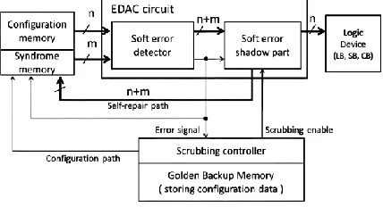
Fig.1 shows the proposed fault tolerant structure which contains a memory block, EDAC circuit, reconfigurable device and scrubbing controller. The golden backup memory block stores configuration data and is not easily influenced by an SEU, For instance, it could be a ROM on or off the chip. Compared to the original reconfigurable architecture, we placed a DEAC circuit between the configuration memory block and the reconfigurable logic device. Fig.2 shows details of the EDAC circuit. The circuit has the function of exporting correct values to a reconfigurable device when one or two event upsets occur in the configuration and syndrome memory blocks. Moreover the soft errors are instantly repaired with the self-repair path. The EDAC circuit is composed of two parts, the soft error detector and soft error shadow part. The soft error detector is composed of n bit configuration memory inputs, m bit syndrome memory inputs, n + m sets of delay circuits, and an error checking circuit. The soft error shadow part is mainly composed of multiplexers and the same number of D-Latches as the configuration and syndrome memory inputs. The error checking circuit is based on a reed Solomon code algorithm that can detect and correct multi-bit error.
Fig. 1. Proposed dependable structure.
The delay circuits are to ensure that the ERROR signal comes to the multiplexer faster than the configuration memory export signals.
Fig. 2. Proposed EDAC circuit
51 Fig. 3. Operation flow of proposed structure
Meanwhile, the configuration and syndrome memory block write enable is turned on by the ERROR signal and their values are recovered through the self-repair path (F). Thus, the proposed EDAC circuit can shadow and recover from soft errors. If the occurring event upsets are more than two bits in one such structure or if an SEU occurs in the D-Latches when the multiplexer is exporting values from them, a soft error may be introduced in to the device. Therefore, a conventional configuration memory scrubbing technique must be applied. If the scrubbing controller detects the ERROR signal changes to “1” for a certain time, which means the EDAC circuit cannot return to the normal state by itself, the scrubbing trigger is enabled. The reconfigurable device should be stopped and a conventional serial reconfiguration operation can be proposed.
2.1. Reed-Solomon Code
Many digital signaling applications in broadcasting use forward error correction, a technique in which redundant information is added to the signal to allow the receiver to detect and correct errors that may have occurred in transmission. Many different types of code have been devised for this purpose, but Reed-Solomon codes have proved to be a good compromise between efficiency and complexity. A particularly important use of a Reed-Solomon code for television applications is in the DVB-T transmission standard.
2.1.1 Reed Solomon encoder
(15, 11) and (255,239) Reed-Solomon code has been implemented using Xilinx 14.2 Software. These two codes could correct up to 2 and 8 errors respectively. The word length in each symbol is 4 and 8 bits respectively and the codes are based on Galios fields with 16 and 256 elements respectively. The code generator polynomial for the first code is:
g(x)=x4+15x3+3x2+x+12 ………... (1)
While for the second one is:
g(x)=x16+59x15+13x14+104x13+189x12+68x11+209x10+30x9+ 8x8+163x7+65x5+229x4+98x3+98x2+36x+59…… (2)
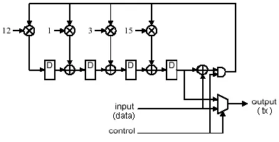
The structure of implemented (15, 11) Reed-Solomon encoder is shown in Fig4. All data paths in Fig.4 provide for 4 bit values. For Reed Solomon codes, the code minimum distance is given by [9]
dmin = n - k + 1 = 15-11+1 = 5………... (3)
This code is capable of correcting any combination of t or fewer errors, where t can be expressed as [10]
t = (dmin-1)/2 = 2 ……….… (4)
During the message input period, the selector passes the input values directly to the output and AND gate is enabled. After the eleven calculation steps have been completed the remainder is contained in the D-type registers. The control waveform then changes so that the AND gate prevents further feedback to the multipliers and the four remainder symbol values are clocked out of the registers and routed to the output by the selector. For (255,239) encoder, the number of stages would be 16 with multipliers coefficients obtained from the generator polynomial corresponding to the code Eqn.(2) while data paths provide for 8 bit values.
Fig. 4. Reed Solomon encoder
2.1.2 Reed Solomon decoder
Fig.5 shows the block diagram of the implemented Reed-Solomon Decoder. In Fig.5, the first process is to calculate the syndrome values from the incoming codeword. These are then used to find the coefficients of the error locator polynomial Λ1….. Λv using Berlikamp algorithm. The error locations are identified by the Chien search and the error values are calculated using Forney’s method. As these calculations involve all the symbols of the received codeword, it is necessary to store the message until the results of the calculations are available. Then, to correct the errors, each error values are added (modulo-2) to the appropriate location in the received codeword.
52 2.1.2.1 Syndrome Calculation
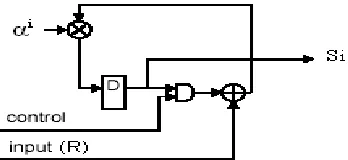
The syndrome values are computed as follows: first dividing the received polynomial by each of the factors (x+αi) of generated polynomial resulting a quotient Qi(x) and a remainder as shown in Eqn (5)
R(x)/(x+αi) = Qi(x)+Si/(x+αi) for 0<i<2t+1 …… (5)
Where: t is the number of error code words that could be corrected. Rearranging Eqn.(5) produces:
Si=Qi(x)×(x+αi)+R(x) ………..…………... (6)
Substituting x=αi in Eqn(6), we get:
Si=R(αi)=Rn-1(αi)n-1+Rn-2(αi)n-2+…+R1αi+R0…(7)
Where, the coefficient Rn-1 …. R0 are the symbols of the received codeword. This means that each of the syndrome values can also be obtained by substituting x=αi in the received polynomial. Fig.6 shows the hardware arrangement used for syndrome calculation.
Fig. 6. Syndrome Calculation
2.1.2.2 Berlikamp Algorithm
Berlikamp algorithm is one of the more efficient iterative techniques for finding the coefficients of error locator polynomial Λ1…..Λv in Eqn (8).
Si+v+Λ1Si+v-1+….+ΛvSi=0 for i=0,.,2t-v-1 … (8)
and the coefficients of error magnitude polynomial Ω0 ……… Ω0 in the following equation:
Ω(x)= [S(x)Q(x)] mod x2t …...……… (9)
This is done by approximating error locator polynomial, starting with Λ(x)=1, then at each stage, an error value is formed by substituting the approximate coefficients in equations corresponding to the value of v. The error is then used and reduces to refine a correction polynomial, which is then added to improve the approximation Λ(x). The process ends when the approximate error locator polynomial checks consistently with the remaining equations. As soon as the coefficients of error locator polynomial is obtained, the coefficients of the error magnitude polynomial could be computed from Eqn(9) in which any terms of degree x2t or higher in the product are ignored.
2.1.2.3 Calculation of Error Values: Forney Method Forney’s algorithm is an efficient method to compute error values Z1….Zv. Here, the error value is computed using Eqn(10):
Z j= Q(xj-1)/Λ′(xj1) ……….…………. (10)
Where, Λ′(xj-1) is the derivative of Λ(x) for x=xj-1 only gives valid results for symbol positions containing an error. If the calculation is made at other positions, the result is generally non-zero and invalid. The Chien search is therefore needed to identify the error position. Fig. 7shows the hardware for the error value calculation. In this figure, γ is a common constant for all Λi and Ωi coefficients.
Fig. 7. Error Calculation
2.1.2.4 Chien Search for Error Positions
It is a simple operation at which different element values of Galios Field are substituted successively in Λ(x) equation. The substitution value that produces a value of zero in Λ(x) would identify the error positions. Fig. 8 shows the hardware of Chien search.
Fig. 8. Hardware of chein search
3. Simulation Results
3.1 Simulation result for Hamming Code
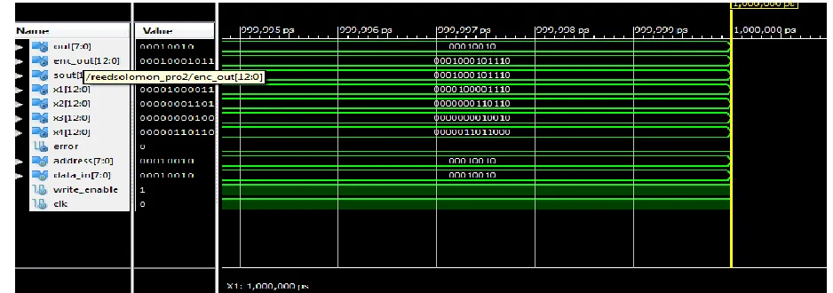
53 3.2 Simulation result for Reed Solomon Code
Fig 10 shows the simulation result for reed Solomon code. Reed Solomon code also detects and corrects the error, but it has the capability of correcting more than single bit. The out is the final output which displays the correct output. Correcting multi bit errors is the only difference. The signals x1, x2, x3 and x4 are results of encoding steps.
3.3 Performance Comparison
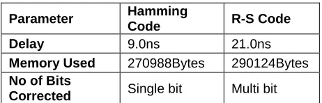
Table 1 Performance Comparison
Parameter Hamming
Code R-S Code
Delay 9.0ns 21.0ns
Memory Used 270988Bytes 290124Bytes No of Bits
Corrected Single bit Multi bit
From Table 1, we can infer that Reed Solomon code can correct more number of bit errors than Hamming code. Reed-Solomon code is a powerful class of nonbinary block code, particularly useful for correcting burst errors. Because coding efficiency increases with code length, Reed-Solomon codes have a special attraction. They can be configured with long block lengths (in bits) with less decoding time than Hamming code of similar lengths. This is because the decoder logic works with symbol-based rather than bit-based arithmetic. Hence, for 8-bit symbols, the arithmetic operations would all be at the byte level. This increases the complexity of the logic, but it also increases the throughput
4. Conclusion
In this paper, we proposed a Reed Solomon code based Error Detection and Correction (EDAC) circuit for reconfigurable systems. The proposed Reed Solomon code based EDAC circuit can tolerate and repair SEUs that occur in the configuration memory of embedded reconfigurable systems instantly without any excess circuits. It can detect and correct multi-bit error whereas the existing hamming code based EDAC circuit can detect two bit error but can correct only one bit error. Moreover, as the FPGA array size increases, the dependability advantage of EDAC increases. However the main drawback of this method is that it requires greater area overhead, but at the same time has higher processing speed. The EDAC circuit requires more area overhead, and it is actually a big problem in VLSI design process. So future work can be done by varying the architecture to decrease the area overhead and delay.
REFERENCES
[1]. Z.Qian, I. Yoshihiro, A. Motoki, I. Masahiro and S. Toshinori, “A Novel soft error detection And correction circuit for embedded Reconfigurable systems” IEEE embedded Systems letters, vol. 3, no. 3 sep 2011.
[2]. Xilnx, Inc., Device Reliability Report Nov. 2010, UG116 (v5.11).
[3]. Actel, Inc., Single-Event Effects in FPGAs 2007.
[4]. D. F. Heidal et al., “Single-event upsets and Multiple bit upsets on a, 45 nm SOI SRAM,” IEEE Trans. Nuclear Sci., vol. 56, no. 6,pp. 3499 -3504, Dec.2009.
[5]. K. Kyriakoulakos and D. Pneymatikatos, “A Novel SRAM-based FPGA architecture for Efficient TMR fault tolerant support” in proc FPL2009 Prague Czech Republic, sep 2009, pp 193-198.
[6]. C. Bolchini, A.Miele, and M.D. Santambrogio, “TMR and partial dynamic reconfiguration to Mitigate SEU faults in FPGAs,” in proc. DFT 2007, sep.2007,pp.87-95.
[7]. F. Lima, L. Carro, and R.Reis, “Reducing pin And area overhead in fault tolerant FPGA-Based designs,” in proc. FPGA2003, Monterey, CA, Feb. 2003, pp. 108-117.
[8]. Y. Ichinomiya, M. Amagasaki, M.Kuga and T.Sueyoshi, “Soft-error tolerability analysis for Triplicate circuit on an FPGA,” in proc SASIM2010, Taipei, Taiwan, oct. 2010, pp. 448-453.
54 Fig. 9. Simulation result for Hamming Code