Fatigue Behavior And Damage Modeling Of Train
Wheels In Different Cases Of Loading
Walid Roundi, Abdellah El Gharad
Abstract: The goal of this study is to highlight the various stress and strain states responsible for degradations of the couple wheel/rail, so the model is applied in three cases of loading, order to compare the results obtained for the three cases and the numerical method applied in this study is that of the finite elements to obtain the form of nodal solution in a very detailed way in the zones which are the seat of stress concentration, deformations and displacements, the results of this study also make it possible to define a strategy of maintenance. The study also shows the fatigue of the wheel, characterized by the lifespan, the safety coefficient and result of damage.
Index Terms: Fatigue, Damage, Railway, Modeling, train wheel, degradation, displacements
————————————————————
1
I
NTRODUCTIONThe wheels and rails rail are affected by damage such as wear and fatigue. As a first step, we are interested in the study and modeling of mechanical behavior of wheels and rails that show us the influence of these degradations in the stability of vehicles, so comfort and security. We present our numerical simulation model on the mechanical behavior of the rail wheel contact in three cases of loading. The phenomenon of the damage of wheels and rail wear are among the major concerns of the officials of the railway sector. Vehicles on tires (trucks, buses, etc. . ) have a contact area between the road and the tire between 25.4 mm and 177.8 mm in diameter. This large contact surface involves a great friction. Which also called adhesion, and which allows the vehicle to combat the inertial force during acceleration and braking. Wagons and locomotives have a contact surface between the wheel and the rail that exceeds 6.35 mm. This small area for a 100 times more important than self weight, does not give much of accession.
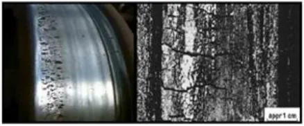
Fig. 1. Fatigue surface failure of a train wheel
So it is estimated that 50-90% of structural endommagement is due to fatigue, thus there is a need for quality fatigue design tools. This is why many designers and analysts use "in-house" fatigue programs which cost much time and money to develop. It is hoped that these designers and analysts, given a proper library of fatigue tools could quickly and accurately conduct a fatigue analysis suited to their needs. Finite element modeling of any solid component consists of geometry generation, applying material properties, meshing the component, defining the boundary constraints, and applying the proper load type. These steps will lead to the stresses and displacements in the component.
Fig.2. Crack initiation in a train wheel
2
F
INITE ELEMENT METHODThe finite element method is a technique for approximate equations for governing a differential system with a set of algebraic equations relating a limited number of variables. The methods are popular because they can easily, be programmed. The finite element techniques were originally developed for structural problems, but they have been extended to many problems on the ground. The solid is decomposed into elements of simple geometric shape with common sides and who‘s the vertices or nodes are points of articulation of several parts between them. These nodes are the points of application of internal or external forces. The decomposition operation is the mesh.
_____________________
Walid Roundi 1: PhD Student, Department of Mechanical Engineering, Moroccan Laboratory of Innovation and Industrial Performance (LaMIPI) , Higher School of Technical Education of Rabat, Mohammed V Souissi University, Rabat, Morocco.
297
3
M
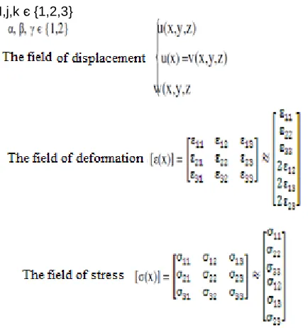
ATHEMATICAL MODELWe will work within the framework of small deformations; this implies that the reference position remains the initial position. Loads can be on volume or surface. Solving a problem of structure is to study three vector fields and their relationship:
The fixed reference: R (O, x1, x2, x3)
I,j,k є {1,2,3}
Relation between deformation and displacement:
E : modulus of elasticity (Young's modulus). υ: Poisson coefficient.
4
M
ODELING OF THE MECHANISMIn this study a simulation was conducted on an actual Mechanism (fig 3). The Finite element analysis was performed to obtain the variation of stress magnitude at critical locations. The figure 4 shows the geometry of Mechanim for Analysis, the Model created by CAD software for further analysis.
Fig.3. real rail and wheel of train
Fig. 4. Mechanism in 3D
Fig. 5. drawing of the mechanism
5
B
OUNDARY CONDITIONSFig. 6. Boundary conditions
6
A
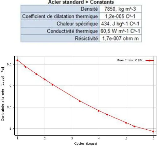
PPLYING MATERIALSteel used in the manufacture of railway wheels and rails is ER7. The table below describe the characteristics of the material and the description of the mechanical safety characteristics.
Fig. 7. Constraint V/S cycle
Fig.8. Constraint V/S Deformation
Fig. 9. Strain V/S Reversals to faillure
7
R
ESULTAS:
7.1 Static study
The von Mises stress is often used in determining whether an isotropic and ductile metal will yield when subjected to a complex loading condition. This is accomplished by calculating the von Mises stress and comparing it to the material's yield stress, which constitutes the von Mises Yield Criterion, we can define the von mises stress as:
299 Fig. 11. Result of constraint
Fig. 12. Result of displacement
Figure 10 show the distribution of Deformation induced within the Mechanism body. The maximum values are goes up 6.13e-7 Pa.
Figure 11 show the distribution of Von mises stresses induced within the Mechanism body. The maximum values of equivalent stresses are goes up 1.2148e5 Pa.
Figure 12 show the distribution of the displacement induced within the Mechanism body. The maximum values of displacement are goes up to 2,1767e-8 m, which are highly localized and observed at the extremities of the wheels.
7.2 Fatigue study First case of load:
The first type of loading will be alternating and symmetrical as shown in the picture:
Rσ = 1 ; σ max = -σ min ; σm = 0
σ max : maximum stress
σ min : minimum stress
σm :mean stress
Rσ : ratio of the stress
Fig. 13. Life prediction
Fig.14. show the biaxial indicator
Fig. 15. Factor of safety
Fig. 16. Result of constraint
The maximum values are goes up 0.883.
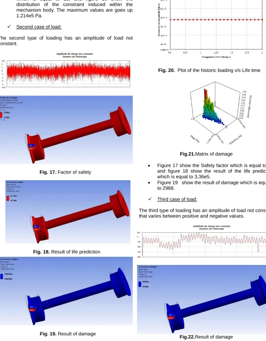
Figure 15 show the result of the factor of safety which is equal to 15, and figure 16 show the distribution of the constraint induced within the mechanism body. The maximum values are goes up 1.214e5 Pa.
Second case of load:
The second type of loading has an amplitude of load not constant.
Fig. 17. Factor of safety
Fig. 18. Result of life prediction
Fig. 19. Result of damage
Fig. 20. Plot of the historic loading v/s Life time
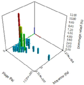
Fig.21.Matrix of damage
Figure 17 show the Safety factor which is equal to 15 and figure 18 show the result of the life prediction which is equal to 3,36e5.
Figure 19 show the result of damage which is equal to 2968.
Third case of load:
The third type of loading has an amplitude of load not constant that varies between positive and negative values.
301 Fig.23.Life prediction
Fig.24. Plot of the historic loading v/s life time
Fig.25.Matrix of damage
Figure 24 show the historic loading v/s Life time and figure 23 show the result of the life prediction which is equal to 2e7 .
Figure 22 show the result of damage which is equal to 50.
8
C
ONCLUSION:
We presented in this study the modeling of the damage and fatigue behavior of the wheel – rail mechanism, to determine the various factors responsible for degradation and fatigue. The results of the wheel indicate that the largest displacement is directed to the loading direction which is consistent with the initial conditions. On the other hand and according to the fatigue study we can notice that the third type of loading is the most favorable since it has the least possible damage with a lifetime higher than the other cases of loading.
R
EFERENCES[1] A. Needleman, ‗An analysis of decohesion along an imperfect interface‘, Int. J. Fracture, 42, 21{40 (1990).
[2] A. Carpinteri, Mechanical Damage and Crack Growth in Concrete, MartinusNijho, Dordrecht, The Netherlands, 1986.
[3] J. R. Rice, ‗Dislocation nucleation from a crack tip: an analysis based on the peierls concept‘, J. Mech. Phys. Solids,40, 235{271 (1992).
[4] A. T. Zehnder and A. J. Rosakis, ‗Dynamic fracture initiation and propagation in 4340 steel under impact loading‘,Int. J. Fracture, 43, 271{285 (1990).
[5] G. I. Barrenblatt, ‗The mathematical theory of equilibrium of cracks in brittle fracture‘, Adv. Appl. Mech., 7, 55{129 )(1962).
[6] Shenoy, P. S. and Fatemi, "Connecting Rod Optimization for Weight and Cost Reduction", SAE Paper No. 2005-01-0987, SAE 2005 Transactions: Journal of Materials and Manufacturing.
[7] Z. Mourelatos, ―An analytical investigation of the crankshaft flywheel bending vibrations for a V6 engine,‖ SAE Paper 951276, 1995.